¶ Introduction
The Design Definition File (DDF) provides a comprehensive outline of the camera system integrated into the Firehorn rocket. This document specifies the design’s functionality, performance, physical characteristics, and interfaces, ensuring compliance with mission constraints and technical requirements.
The camera module is designed to capture high-resolution images and videos throughout the rocket’s flight. It is robust and lightweight, following a modular approach to simplify assembly, testing, and maintenance.
¶ System Overview
The system consists of the following components:
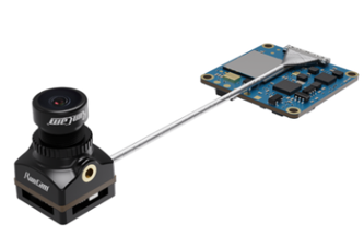
- Camera Unit: RunCam Split 4 v2 (Image Sensor & Processing Board)
- Custom PCB: Handles signal conversion and power regulation
- Mechanical Mounts: Custom-designed brackets for aerocover integration
- Communication Protocol: I2C → I2CAN → UART conversion
- Thermal Dissipation: Aluminum heat block for cooling
- Storage System: Internal SD card storage
¶ Camera Specifications and Performance
The RunCam Split 4 v2 was selected for its high-definition recording capabilities and lightweight structure, meeting the following performance criteria:
- Resolution: 2.7K @ 60 fps
- Field of View: 140°
- Power Consumption: 2.25 W @ 5V
- Operational Temperature Range: 0°C to 60°C
- Weight: 10.2 g (excluding mounting hardware)
- Data Storage: Onboard SD card (128GB max.)
- Recording Duration: Continuous recording for full flight duration
¶ Mechanical Definition
¶ Camera Placement
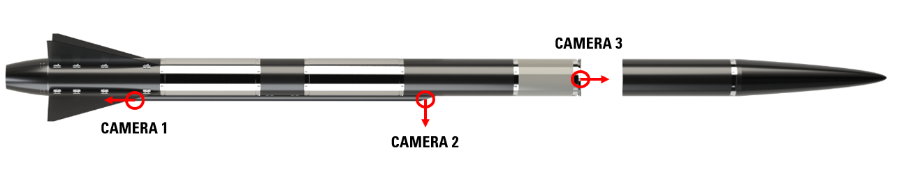
The Firehorn rocket includes three strategically placed cameras:
- Camera 1: Bottom aerocover for downward recording.
- Camera 2: Top aerocover for radial flight footage.
- Camera 3: Top of the avionics bay for parachute deployment monitoring.
¶ Camera Supports
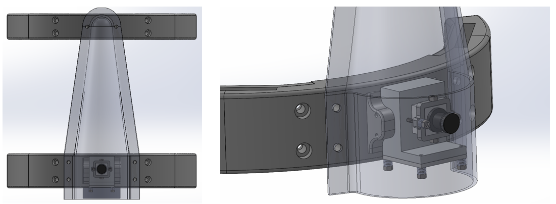
Bottom Support (Camera 1)
- Material: PETG
- Weight: 125.5 g
- Function: Provides structural support and vibration damping
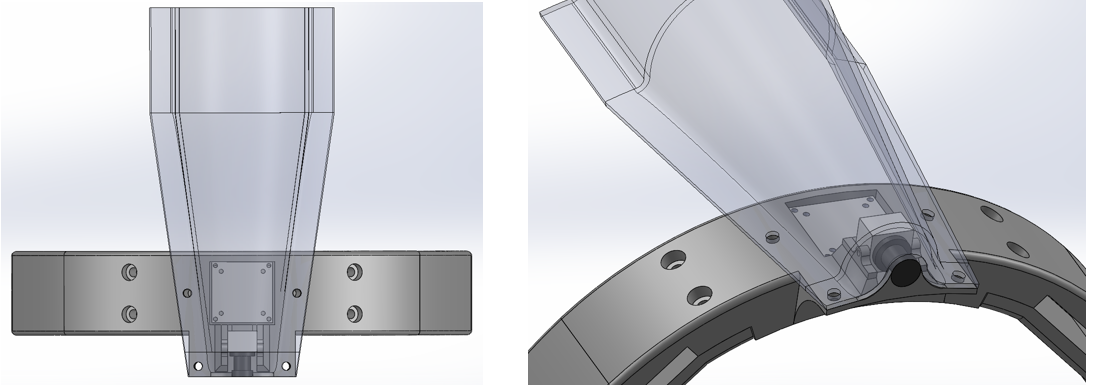
Top Support (Camera 2)
- Material: PETG and Aluminum (for heat dissipation)
- Weight: 221.66 g
- Function: Provides thermal dissipation and vibration mitigation
¶ Electronic Definition
¶ Communication System
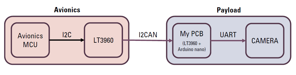
The camera system interfaces with avionics via a protocol conversion system:
- Avionics MCU → I2C to I2CAN (LT3960)
- Custom PCB → I2CAN to UART (Arduino Nano)
- Camera Module → UART for control and power
¶ PCB Design
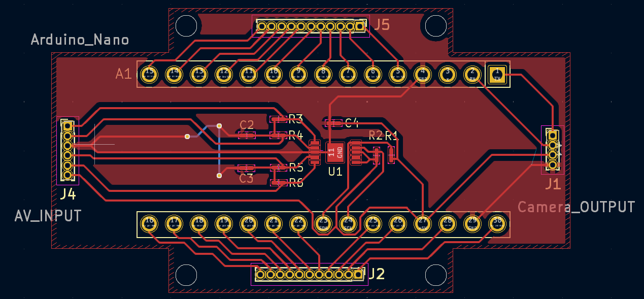
The custom PCB provides:
- Signal conversion between I2C, I2CAN, and UART
- Power regulation for the camera
- Secure connectivity to avionics
¶ Schematic Diagram
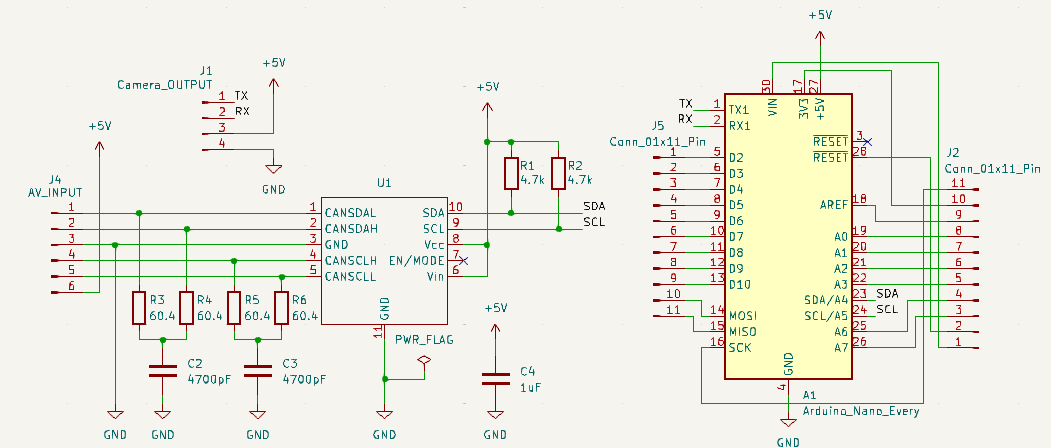
The circuit is designed to ensure:
- Stable voltage regulation
- Seamless communication between avionics and camera
- Compact design for efficient integration
¶ Interfaces with Other Systems
The camera module interacts with other subsystems through the following interfaces:
- Power Interface: Direct 5V power supply from a dedicated battery module (AV)
- Communication Interface: UART-based control signals from avionics
- Mechanical Interface: Integrated within the aerocover, secured with vibration-resistant mounts
- Thermal Interface: Contact cooling via aluminum heat block
¶ Thermal Management
Thermal regulation is a key challenge, as cameras generate heat over extended operation. Testing was conducted to measure temperature stabilization over time.
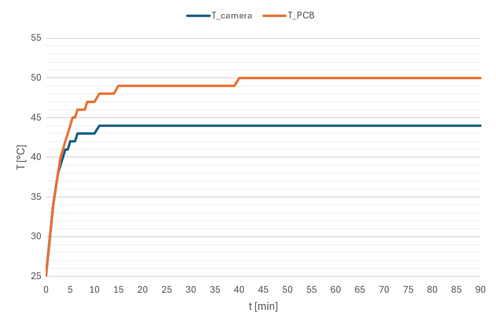
Results from a 90-minute test showed:
- Standalone Camera stabilized at 44°C
- Standalone PCB stabilized at 50°C
- Camera + Aluminum Block stabilized at 36.07°C
To mitigate overheating, an aluminum heat block is used in the top support structure, ensuring efficient thermal dissipation.
¶ Verification and Testing
The following tests have been conducted to validate the design:
- ✅ Communication Testing: The I2C → I2CAN → UART conversion has been successfully tested, ensuring reliable data transmission between avionics and the camera module.
- ✅ Steady-State Temperature Testing: The operational temperature of the camera and PCB has been measured over an extended period.
The following tests are planned before flight integration:
3. Vibration Testing: To ensure resistance to launch-induced mechanical stress.
4. EMI/EMC Compliance Testing: To verify electromagnetic compatibility and avoid interference with avionics systems.
7. Heat Dissipation Testing: To determine the effectiveness of the aluminum heat block in reducing temperature buildup.