¶ Introduction
This document serves as a Design Justification File (DJF) for the Acoustic Levitator Assembly. The main objective of the Acoustic Levitator Assembly is to provide an optimal configuration for accommodating ultrasonic transducers in a way that achieves stable and controlled levitation of a small spherical object. This setup is designed to create a precise acoustic field that can manipulate the position and movement of the object in a controlled airspace without direct contact.
The full report can be found here.
¶ Definitions and Abbreviations
- DJF : Design Justification File
- EuRoC: European Rocketry Challenge
- EPFL: École Polytechnique Fédérale de Lausanne
- CFD: Computational Fluid Dynamics
- BEM: Boundary Element Method
- HT PETG: High-Temperature Polyethylene Terephthalate Glycol
¶ Relevant Knowledge Needed
¶ Acoustic Levitation - Principles
Acoustic levitation operates under two fundamental principles: the Gor'kov potential and the Rayleigh condition.
In acoustic levitation, objects placed within an acoustic field are subjected to forces arising from fluctuations in the surrounding air pressure. These forces are quantitatively described by what's known as the Gor'kov potential. Essentially, the Gor'kov potential is a theoretical construct that provides a mathematical framework for understanding how the pressure variations in the sound waves interact with the physical properties of the object.
This force can be calculated for small, rigid spherical particles using the Gor'kov potential:
Where:
- and are the densities of the fluid (air) and the sphere (particle), respectively.
- and are the speeds of sound in the fluid and sphere, respectively.
- is the acoustic pressure at the center of the sphere.
- is the particle velocity at the center of the sphere.
- is the radius of the sphere.
- and are parameters given by:
The Rayleigh condition is essential for the validity of the Gor'kov potential. It states that the size of the particles, if considered to be perfectly spherical, needs to be smaller than the acoustic wavelength. Some sources suggest that the particles should be at least twice as small as the wavelength.
For a typical 40 kHz transducer used in acoustic levitation:
- Frequency (): 40 kHz
- Speed of Sound in Air (): Approximately 343 m/s (depending on temperature and humidity)
Using the formula for wavelength ():
λ = \frac{c}
For 40 kHz:
= = [cm]
¶ Acoustic Levitator - Requirements
The Goal of the Semester Project is to design a prototype of the Payload experiment that will take flight in the Firethorn Rocket in the EuRoC 2025 competition
This year the Payload is to design an acoustic levitation device that is able to maintain a lightweight body in levitation for the longest time possible from liftoff:
- 2024_C_SE_PL_ACOUSTIC_LEVITATION_EXPERIMENT_01 Declaration of purpose
The payload shall consist of an experiment that will use acoustic levitation to maintain a lightweight body in levitation from liftoff and for the longest duration possible.
The levitation device has two main objectives as defined by the requirements below:
- Maintain the particle in levitation under up to 8g of vertical acceleration
- Maintain the particle in levitation under up to 3g of radial acceleration
-
2024_C_SE_PL_ACOUSTIC_LEVITATION_EXPERIMENT_18
Experiment acceleration resistance
The payload experiment shall function when subjected to vertical accelerations of at least [8]g's. -
2024_C_SE_PL_ACOUSTIC_LEVITATION_EXPERIMENT_19
Experiment acceleration resistance
The payload experiment shall function when subjected to radial accelerations of at least [3]g's.
¶ Simulation of the Lab Acoustic Levitator
¶ Overview
EPFL has a lab that is dedicated to research on acoustics (The lab supervising this semester project). Among some of the research they conduct they have a practical where students learn how to use a small scale acoustic levitator and the drawbacks associated to it. The acoustic levitator in their set up is very simple but can give a good indication of the drawbacks and capabilites of such a technology The simulation of the lab acoustic levitator is conducted using Matlab code to predict and analyze the behavior of the levitator under various operational conditions. This simulation is critical for understanding how the device will perform, particularly in terms of the forces exerted on the levitated object [Dolev, 2023].
¶ Simulation Parameters
- Vertical Acceleration: The lab levitator is capable of achieving a maximum vertical acceleration of up to 6g. This parameter indicates the intensity of the upward force that can be applied to the levitated object.
- Radial Acceleration: When no vertical acceleration is applied, the maximum radial acceleration can reach up to 0.7g. However, when vertical acceleration is present, the radial acceleration is reduced to 0.1g. This demonstrates how the forces within the levitator interact and influence each other.
¶ Prescaler Setting
- A prescaler of 1 is used in the simulation, which assumes that the simulated results perfectly match the real-world behavior of the levitator. These readings therefore need to be taken with a grain of salt.
¶ Implications
- Challenges with Radial Acceleration: The most significant challenge identified through simulation is achieving functionality under conditions where the radial acceleration reaches 3g. The designs which will be presented in the rest of the document will try to maximise the levitators capabilites under radial constraints
¶ Own Simulation Environment for Acoustic Levitation
¶ Overview
Creating a bespoke simulation environment for the acoustic levitator involves detailed computation of forces affecting the levitated objects, including the application of the Gor'kov potential. This simulation environment is essential for accurately predicting and optimizing the levitator's performance under various conditions.
¶ Simulation Techniques
Two primary computational methods can be employed to simulate the acoustic levitation phenomena:
-
Numerical Computation via the Boundary Element Method (BEM): This method is well-suited for problems where the domain is unbounded, such as acoustic fields. BEM focuses on solving linear partial differential equations, specifically Helmholtz equations, which are fundamental in acoustic simulations.
-
Computational Fluid Dynamics (CFD): CFD can be used to simulate the fluid dynamics around the levitated object, providing insights into how acoustic waves propagate through the medium and interact with objects. This approach is particularly useful for understanding complex interactions in the levitator, such as turbulent flows and the impact of different fluid properties.
¶ Implications and Practical Application
- Dependence on Simulation for Conclusions and Decisions: Having a proprietary simulation environment means that all conclusions and operational decisions regarding the acoustic levitator can be based on comprehensive experimental data generated within this controlled setup.
¶ Consideration for Implementation
-
Project Scope and Resource Allocation: Developing a dedicated simulation environment is a substantial undertaking that would likely require its own semester project. This project would not only involve software development and simulation setup but also extensive testing and validation against experimental data.
-
Benefits: Owning a simulation environment allows for tailored adjustments and optimizations specific to our levitator's design and operational needs. It provides a powerful tool for enhancing performance, predicting system behavior under new conditions, and driving innovations in acoustic levitation technology.
Creating this environment would be immensely beneficial, allowing for in-depth studies and refinements specific to our objectives. However, due to the complexity and resources needed, it would necessitate dedicated time and expertise, ideally suited as another semester-long project. All the data we will gather for our acoustic levitator will therefore have to be experimental data.
¶ Testing the Device
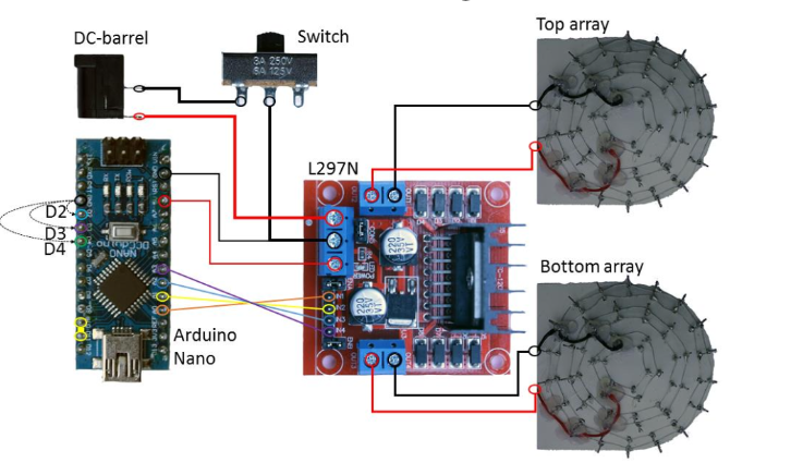
To systematically test and select the optimal levitator design, we have procured a levitation kit. This kit, developed by the University of Bristol, features simple and cost-effective electronics that can be easily reused for various experimental configurations. Our approach involves the following steps:
-
Setup the Levitation Kit:
- Utilize the Arduino Nano to generate square wave signals.
- Employ the L297N Dual H-Bridge motor driver to amplify the signals.
-
Experiment with Different Levitator Designs:
- Use the provided components to test various levitator configurations which will be presented in the following section of the DJF.
- Analyze the performance of each design to determine the most effective setup.
-
Select the Optimal Design:
- Based on the experimental results, select the levitator design that performs best in terms of stability and efficiency.
This structured approach ensures a thorough evaluation of potential designs, leveraging the simplicity and versatility of the DIY levitation kit without the need of building a complex simulation environment to test our design.
¶ Design Options
¶ Transducer Choice
¶ Evaluation of Different Commercially Available 40kHz Air Transducers
| Model | Diameter (mm) | Acoustic Output (Pascal/meter*volt) | Phase Standard Deviation (degrees) |
|---|---|---|---|
| Manoshi MSO-P164OH10TR | 16 | 0.25 SD=0.04 | 8.7 |
| MSO-A164OH10T | 16 | 0.36 SD=0.02 | 9.2 |
| MSO-P104OH07T | 10 | 0.13 SD=0.02 | 13.9 |
| Ningbo FBULS1007P-T | 10 | 0.14 SD=0.02 | 13.9 |
| Murata MA40S4S | 10 | 0.17 SD=0.01 | 3.8 |
| MultiComp MCUST10P40B07RO | 16 | 0.25 SD=0.04 | 33.1 |
| MCUSD16A40S12RO | 16 | 0.21 SD=0.03 | 18.3 |
Research by Asier Marzo, Adrian Barnes, Bruce W. Drinkwater, Faculty of Engineering, University of Bristol [Stephens, 2007]
Key Measures:
- "The key factor measured was the pressure generated at a fixed distance under the same excitation signal."
- "Another important measure is the standard deviation of the phase; transducers were found to output slightly offset signals even if they were fed with the same signal and the acoustic pressure recorded at the same distance."
Explanation:
When selecting the appropriate transducers for our acoustic levitation experiments, two critical factors were taken into account: the acoustic output (pressure generated) and the phase standard deviation.
-
Acoustic Output: The pressure generated by each transducer at a fixed distance under the same excitation signal was the primary factor measured. This measure is crucial as it determines the ability of the transducer to create a sufficient acoustic pressure field to achieve levitation. Higher acoustic output indicates a stronger ability to manipulate particles.
-
Phase Standard Deviation: This measure accounts for the variability in the signals produced by the transducers. Even when fed with the same excitation signal, transducers can produce slightly offset signals, which can impact the uniformity of the acoustic pressure field. A lower phase standard deviation is preferable as it indicates more consistent performance and less signal variation among transducers.
¶ Comparison of 16 mm vs 10 mm Diameter Transducers
| Diameter | Advantages | Disadvantages |
|---|---|---|
| 16 mm | - Better Acoustic Output - Better phase standard deviation |
- Higher Cost - Not ideal given our dimension constraints - Not often used in other acoustic levitators |
| 10 mm | - Lower Cost - Often used in acoustic levitators (including Robotics Practicals) - Smaller (more transducers can be implemented on a smaller surface) |
- Worse phase standard deviation - Worse Acoustic Output |
¶ Rationale for Choosing 10 mm Transducers
The decision to utilize 10 mm diameter transducers for our acoustic levitator was driven by several practical considerations:
-
Cost-Effectiveness: The 10 mm transducers are significantly less expensive, making them a more economical choice for our project, especially when multiple units are required.
-
Space Efficiency: Their smaller size allows for a denser configuration of transducers within the limited space of our levitator design. This is particularly beneficial in applications where compactness is crucial.
-
Prevalence in Use: These transducers are commonly used in similar applications, ensuring a reliable performance based on established use cases. Their commonality also implies better availability and community support for troubleshooting and optimization.
-
Trade-off Acceptance: Although they exhibit worse phase standard deviation and acoustic output compared to 16 mm transducers, these disadvantages are deemed acceptable given the benefits of cost and size. Moreover, these limitations can often be mitigated through careful calibration and system optimization.
By choosing 10 mm transducers, we aim to build a cost-effective, compact, and efficient levitator that meets our specific application needs while staying within budgetary and spatial constraints.
¶ Final Transducer Choice: Murata MA40S4S
¶ Reason:
- Much better performance in acoustic output in comparison to the Ningbo FBULS1007P-T and the MSO-P104OH07T transducers for a slightly higher price per unit of 4.8 CHF.
- Same transducers that are used in the Robotics Practicals.
- Much better performance when it comes to Phase standard deviation, which is significantly lower than the 16 mm transducers.
¶ Graphical Analysis
Below is a graph illustrating the trapping force performance of a transducer, depending on the phase standard deviation of the transducers. This graph highlights the superior performance of the Murata MA40S4S, especially notable in its low phase standard deviation which correlates with more stable and efficient trapping force.
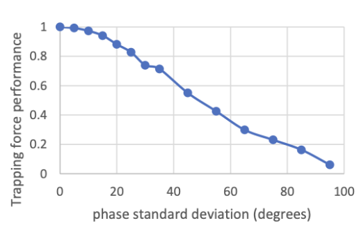
Table: Simulation of the trapping force performance of TinyLev (Another type of Transducer) depending on the phase standard deviation of the transducers. by Asier Marzo, Adrian Barnes, Bruce W. Drinkwater, Faculty of Engineering, University of Bristol [Stephens, 2007]
The Murata MA40S4S demonstrates outstanding stability and efficiency in acoustic levitation especially when considering the very strong impact Phase Standard deviation has on such devices, making it the ideal choice for applications requiring precise control and high performance.
¶ Acoustic Levitator Design
¶ Context:
- Since we can't improve the performance of the Robotics Practicals levitator using a different transducer option, we need to significantly change the levitator design to improve performance.
- Various designs inspired from different papers will be tested and the best one will be selected.
¶ Concept:
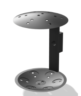
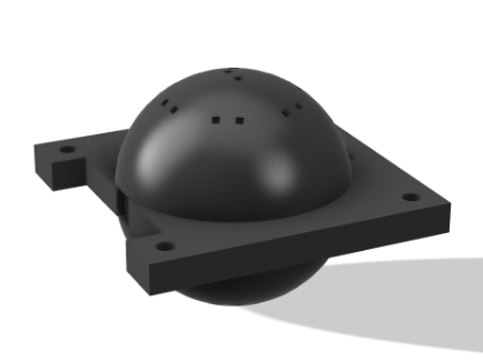
This design builds on the Robotics Practicals design by implementing an optimized arrangement of transducers based on the principles of optimal circle packing in a hexagonal pattern. This configuration maximizes the coverage and uniformity of the acoustic field, crucial for enhancing the levitation capabilities of the system. It is inspired by the design of the Acoustic Levitation Kit that was made by the university of Bristol. Here below is a picture of our design [Stephens, 2007].
¶ Transducer Layout:
-
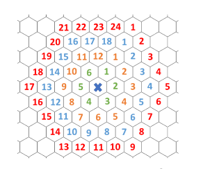
Hexagonal Packing: The transducers are arranged in a hexagonal pattern, which is known for its efficiency in space utilization and coverage. This pattern is especially beneficial in applications like acoustic levitation where uniform distribution of acoustic pressure is necessary.
-
Detailed Transducer Arrangement:
-
Initial Setup: The initial configuration includes 7 transducers — one at the center and six surrounding it in a ring. This setup forms the basic module of the hexagonal packing pattern.
-
Scalability: While the basic setup includes 7 transducers, the design allows for easy scaling by adding more transducers following the same hexagonal pattern. This scalability makes the design versatile for different sizes and shapes of the levitated objects.
¶ Focusing Strategy Choice:
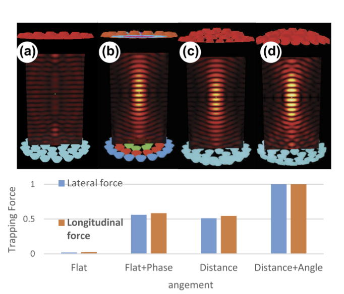
In the development of our acoustic levitator, we consider several focusing strategies that significantly influence the trapping force capabilities of the system. Each strategy comes with its own set of trade-offs in terms of complexity, cost, and performance:
-
(a) Flat Surface Transducers: This strategy employs a straightforward construction method, using flat surface transducers that are easier and cheaper to produce and assemble. However, the main drawback is the relatively low trapping force they generate, which may not be sufficient for applications requiring the manipulation of heavier or more resilient materials.
-
(b) Electronic Phase Adjustment: By dynamically adjusting the phase of the acoustic waves through electronic control, this method can significantly enhance the trapping force. The electronic phase adjustment allows for precise control over the acoustic field, enabling better manipulation of the levitated objects. However, this method requires advanced, complex electronics which increase the system's cost and complexity, potentially making it less accessible for smaller-scale or budget-constrained projects.
-
(c) Fixed Physical Phase-Delays: As an alternative to electronic controls, fixed physical phase-delays can be implemented. This method involves structurally designing the transducer setup to create phase delays, which manipulate the acoustic field similarly to electronic adjustments. This strategy offers a performance comparable to electronic phase adjustment but with potentially reduced complexity and cost since it does not rely on sophisticated electronic systems.
¶ Comparative Performance Analysis
The graph below, taken from a study by the University of Bristol, illustrates the trapping forces achieved with different trapping strategies. It plots the trapping force relative to each strategy, providing a visual representation of how each method impacts the overall performance of the levitator.
¶ Optimal configuration:
(d) The vertical transducer movement and orientation strategy has been identified as the most effective method for achieving optimal trapping capabilities. This approach involves adjusting the vertical position and angle of the transducers to align precisely with the levitated object, thereby maximizing the acoustic force exerted directly where it is most effective.
¶ Benefits of Vertical Orientation:
-
Focused Acoustic Energy: By orienting the transducers vertically, the acoustic waves are directed more efficiently towards the levitation point. This concentration of energy results in a stronger and more stable levitation force, capable of handling objects with greater precision and control.
-
Enhanced Stability: Vertical alignment helps maintain the object at the nodal point of the acoustic field, where the opposing forces balance perfectly. This stabilization is crucial for applications requiring high precision and minimal disturbance.
-
Adaptability: Vertical movement allows for quick and easy adjustments to the system, accommodating different sizes and shapes of objects without extensive reconfiguration of the entire setup.
¶ Motor Choice:
- This strategy utilizes a motor similar to how it was done in the Robotics Practicals in order to improve the radial acceleration performance.
Main Problem: Size
- The Levitator Design I + Nema 11 motor which was used in the Robotics Practical don’t fit in the allocated volume.
Solution:
- Nema 17 Pancake Motor.
¶ Design Advantages and Disadvantages
| Aspect | Advantages | Disadvantages |
|---|---|---|
| Design Flexibility | - Flexible design (can easily re-print, add extra transducers, change the distance between the two domes) | - Complicated electronics because of the motor |
| Cost Efficiency | - Requires few transducers (Low cost of the levitation device) | - Motor significantly increases the cost |
| Performance | - Improved radial performance thanks to the motor | - Hard to test |
¶ Conclusion
Despite the benefits outlined, we ultimately decided not to proceed with Design I. While the design presents a flexible and potentially cost-effective solution, we believe that there is still room to find a more optimal configuration that better meets our needs. Additionally, the integration of the motor significantly complicates the testing process, presenting challenges that might hinder efficient development and evaluation. Furthermore, we were quite sure that this design would not be able to hold the 8g accelerations required for our application. These factors led us to continue exploring other design possibilities that may offer improved ease of testing and overall performance without the complexities introduced by the motor system.
¶ Concept:
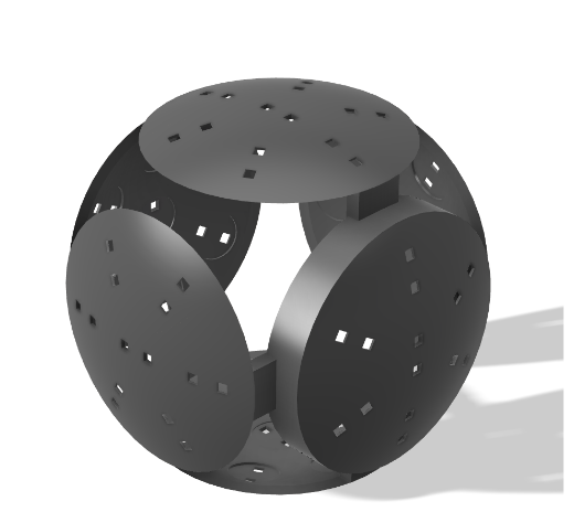
This design integrates a 3-axis transducer arrangement to effectively compensate for radial acceleration forces. The three-axis control allows for precise manipulation of the acoustic field, enhancing stability and control during levitation and is especially effective when it comes to stabilizing a particle under radial accelerations. This design is inspired by various reasearch in the field that have testing similar configurations but at different scales and different applications [Marzo, 2022].
¶ Configuration Details:
-
3-Axis Transducer: Each transducer phase can be adjusted, allowing for precise control over the acoustic forces applied to the levitated objects.
-
Dome Setup: The system comprises 6 domes, each outfitted with 7 transducers, totaling 42 transducers. This setup is designed to ensure a comprehensive and uniform acoustic field.
-
Motor Replacement: This design eliminates the need for motors by having a 3-axis device and having more stability against radial accelerations, which simplifies the mechanical design and reduces maintenance.
¶ Advantages and Disadvantages:
| Aspect | Advantages | Disadvantages |
|---|---|---|
| Testing and Maintenance | Simpler to test due to reduced mechanical complexity | High cost due to the large number of transducers |
| Stability and Performance | Enhances particle stabilization against radial accelerations | Requires significant space |
| Manufacturing and Design | Reduces the need for complex motor systems | Challenges in manufacturing and potential vibration sensitivity |
¶ Conclusions:
While this 3-axis transducer design marks an improvement over previous setups by offering more direct control over levitation forces, there is potential for further optimization. The current design, while effective, still occupies a considerable amount of space and incurs high costs due to the extensive use of transducers. These factors are significant when considering scalability and practical application. We anticipate that these insights will guide the development of Design III, where we aim to address these inefficiencies and refine the system to achieve better optimization and practicality.
¶ Concept:
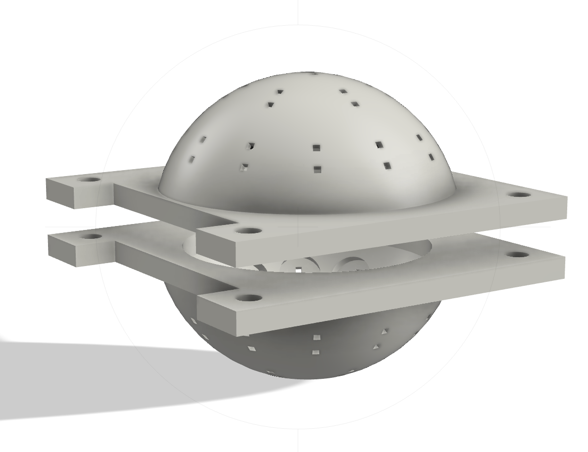
Design III simplifies the overall transducer setup by reducing the number of transducers to 19 per dome, arranged in an optimal configuration that balances lateral and longitudinal force exertion. This design results from continued optimization efforts, focusing on achieving the best trade-off between controlling vertical and radial forces.
¶ Configuration Details:
- Reduced Number of Transducers: Each of the upper and lower domes contains 19 transducers, simplifying the setup and reducing costs.
- Optimal Transducer Placement: The transducers are arranged to optimize the trade-off between lateral and longitudinal forces, enhancing the stability and control of the levitated particles.
- Separation of Upper and Lower Surfaces: The design includes a 8.5 mm gap between the upper and lower dome surfaces. This gap allows us to have our embedded camera system, which monitors and adjusts the levitation process in real-time (further details are provided in the electronic DJF).
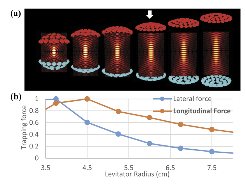
- Graphical Analysis: Below is a graph demonstrating how the levitator’s configuration, specifically the near-spherical design of the domes, impacts the trapping forces. It illustrates that our design configuration allows for a high radial trapping force, which is crucial for maintaining stable levitation. The graph, sourced from a paper published by the University of Bristol, shows the relationship between the levitator radius and both lateral and longitudinal trapping forces.
¶ Advantages and Disadvantages:
| Aspect | Advantages | Disadvantages |
|---|---|---|
| Compactness and Efficiency | Very compact and spatially optimal | Will need rigorous testing as such designs haven’t been used often |
| Cost-effectiveness | The cheapest design among the considered alternatives | |
| Force Balance | Excellent trade-off in stabilizing the particle against vertical and radial forces |
¶ Conclusions:
Design III was selected as the preferred configuration due to its effective balance of transducer economy and performance. It significantly improves upon previous designs by reducing complexity and cost while maintaining high functionality. The chosen setup allows for a compact design, minimizing the space required and simplifying the assembly process. The 8.5 mm gap specifically accommodates the camera system, ensuring unobstructed monitoring of the levitation process. This design will be the basis for further refinement and testing to ensure its feasibility in practical applications.
¶ Design Iterations of Design III
-
Shape and Configuration: The design featured a perfect spherical shape with a small aperture to allow camera visibility inside the levitator. This configuration provided optimal trapping forces due to the symmetry and uniformity of the acoustic field.
-
Material: The sphere was initially 3D printed using regular PETG. While PETG offered sufficient structural resistance for the levitation forces, its high melting point posed challenges during manufacturing.
-
Challenges:
- Accessibility and Utility: Inserting the ball inside the device proved really hard due to the limited aperture size, making the design less practical for manipulation and usage.
- Manufacturing Issues: The low melting point of PETG caused deformations in the levitator structure during the soldering of transducers, impacting the precision and integrity of the assembly.
-
Shape and Configuration: To enhance usability and manufacturing stability, the design was modified to include an 8.5 mm gap between two half-spheres. This gap facilitated camera visibility and also significantly improved access for manipulating the internal components.
-
Material: The second iteration utilized High-Temperature PETG (HTPETG), which retains the structural advantages of regular PETG but with greater resistance to high temperatures.
-
Advantages:
- Transparency and Observation: HTPETG’s slight transparency allowed for better visibility into the device’s operation, providing insights into the levitation dynamics.
- Manufacturing Stability: The high-temperature resistance of HTPETG prevented deformations during the soldering process, ensuring that the device maintained its precise shape and functionality.
By addressing the practical and manufacturing challenges encountered in the first iteration, the second iteration of Design III allowed for better usability and durability of the levitation device, making it more suited for experimental applications.
¶ Relevant Documents
-
Stephens, 2007
Three-axis acoustic device for levitation of droplets in an open gas stream and its application to examine sulfur dioxide absorption by water droplets
Terrance L Stephens, Ralph S Budwig
PMID: 17503939
DOI: 10.1063/1.2424454 -
Marzo, 2022
TinyLev: A multi-emitter single-axis acoustic levitator
Asier Marzo, Adrian Barnes, Bruce W. Drinkwater
© 2022 IEEE
IEEE Transactions on Ultrasonics, Ferroelectrics, and Frequency Control (Early Access) -
Röthlisberger, 2022
Multi-Frequency Acoustic Levitation and Trapping of Particles in all Degrees of Freedom
M. Röthlisberger, G. Schmidli, M. Schuck, J. W. Kolar
ETH Pioneer Fellow Marcel Schuck is developing a robotic gripper that can manipulate small and fragile objects without touching them. The technology is based on sound waves. -
Dolev, 2023
Acoustic Levitation apparatus (Robotics Practicals)
Dolev, Amit; Noseda, Lorenzo Francesco John; Yalcin, Bora; Sakar, Selman
- 2024_C_SE_PL_ACOUSTIC_LEVITATION_EXPERIMENT_01 Declaration of purpose
The payload shall consist of an experiment that will use acoustic levitation to maintain a lightweight body in levitation from liftoff and for the longest duration possible. - 2024_C_SE_PL_ACOUSTIC_LEVITATION_EXPERIMENT_02 Avionics
The payload shall use its own set of avionics that is independent from the main rocket avionics boards. - 2024_C_SE_PL_ACOUSTIC_LEVITATION_EXPERIMENT_03 Data collection
The payload shall store and log all collected data on its own avionics. - 2024_C_SE_PL_ACOUSTIC_LEVITATION_EXPERIMENT_04 Data storage
All data gathered by the camera shall be stored in a 'black box' designed by AV. - 2024_C_SE_PL_ACOUSTIC_LEVITATION_EXPERIMENT_05 Status indicator
The payload shall indicate visually and auditorily whether it is on or off. - 2024_C_SE_PL_ACOUSTIC_LEVITATION_EXPERIMENT_06 Mass
The payload mass shall be between [3000]g and [3990]g. - 2024_C_SE_PL_ACOUSTIC_LEVITATION_EXPERIMENT_07 Volume
The payload shall fit within a [30]x[10]x[10]cm volume. - 2024_C_SE_PL_ACOUSTIC_LEVITATION_EXPERIMENT_08 Structure
The payload shall include its own internal or external structure. - 2024_C_SE_PL_ACOUSTIC_LEVITATION_EXPERIMENT_09 Structure load case
The payload structure shall protect the experiment from axial accelerations loads of at least [60]g's. - 2024_C_SE_PL_ACOUSTIC_LEVITATION_EXPERIMENT_10 Structure load case
The payload structure shall protect the experiment from radial accelerations of at least [3]g's. - 2024_C_SE_PL_ACOUSTIC_LEVITATION_EXPERIMENT_11 Restricted materials
The payload shan't contain any hazardous material such as lead or radioactive elements. - 2024_C_SE_PL_ACOUSTIC_LEVITATION_EXPERIMENT_12 Payload assembly
The payload structure shan't be inextricably connected to other rocket components than the payload supporting structure. - 2024_C_SE_PL_ACOUSTIC_LEVITATION_EXPERIMENT_13 Assembly human needs
The assembly of the payload shall require at most [2] person. - 2024_C_SE_PL_ACOUSTIC_LEVITATION_EXPERIMENT_14 Operation human needs
The operation of the payload shall require no more than [1] person. - 2024_C_SE_PL_ACOUSTIC_LEVITATION_EXPERIMENT_15 Power source
The payload shall be self-powered both on the pad and in-flight. - 2024_C_SE_PL_ACOUSTIC_LEVITATION_EXPERIMENT_16 Autonomy
The payload power source shall have an autonomy of at least [8] hours (with the payload possibly running on 'standby mode' for most of that time). - 2024_C_SE_PL_ACOUSTIC_LEVITATION_EXPERIMENT_17 Budget
The development and construction of the payload shan't cost more than [600]CHF. - 2024_C_SE_PL_ACOUSTIC_LEVITATION_EXPERIMENT_18 Experiment acceleration resistance
The payload experiment shall function when subjected to vertical accelerations of at least [8]g's. - 2024_C_SE_PL_ACOUSTIC_LEVITATION_EXPERIMENT_19 Experiment acceleration resistance
The payload experiment shall function when subjected to radial accelerations of at least [3]g's. - 2024_C_SE_PL_ACOUSTIC_LEVITATION_EXPERIMENT_20 Experiment recording
The payload should include a small camera that can record the experiment. - 2024_C_SE_PL_ACOUSTIC_LEVITATION_EXPERIMENT_21 Assembly time
Assembly of the payload in the launch vehicle shan't take more time than [10]min.