¶ Introduction
This document serves as the Electronics Design Justification File (DJF) for the Acoustic Levitator Assembly. The purpose of this DJF is to outline the rationale behind the electronic and software design decisions made during the development of the Acoustic Levitator. It details the configuration of the electronic components, the functionality of the software that controls these components, and the integration of these elements to achieve the different levitation tasks.
¶ Definitions and Abbreviations
- DJF: Design Justification File
- EuRoC: European Rocketry Challenge
- MCU: Microcontroller Unit
- I/O: Input/Output
- CPU: Central Processing Unit
- LPDDR: Low Power Double Data Rate
- BLE: Bluetooth Low Energy
- CSI: Camera Serial Interface
- DSI: Display Serial Interface
- LSB: Least Significant Bit
- PWM: Pulse Width Modulation
- DC-DC: Direct Current to Direct Current
- ADC: Analog to Digital Converter
- DAC: Digital to Analog Converter
- SPI: Serial Peripheral Interface
- I2C: Inter-Integrated Circuit
- GPIO: General-Purpose Input/Output
- USB: Universal Serial Bus
- HDMI: High-Definition Multimedia Interface
- PETG: Polyethylene Terephthalate Glycol
- M5: Metric 5mm
- HAT: Hardware Attached on Top
- IMU: Inertial Measurement Unit
- L298N: A dual H-bridge motor driver
¶ Electrical System - Requirements
The goal of this project is to design and implement the electrical system for the acoustic levitation payload that will be used in the Firethorn Rocket at the EuRoC 2025 competition.
This year, the electrical system must ensure that the payload can operate independently and meet all specified requirements for data acquisition, power management, and system stability.
¶ Avionics Requirements
The payload must have its own set of avionics and the following capabilities:
-
2024_C_SE_PL_ACOUSTIC_LEVITATION_EXPERIMENT_02
Avionics
The payload shall use its own set of avionics that is independent from the main rocket avionics boards. -
2024_C_SE_PL_ACOUSTIC_LEVITATION_EXPERIMENT_05
Status Indicator
The payload shall indicate visually and auditorily whether it is on or off. -
2024_C_SE_PL_ACOUSTIC_LEVITATION_EXPERIMENT_15
Power Source
The payload shall be self-powered both on the pad and in-flight. -
2024_C_SE_PL_ACOUSTIC_LEVITATION_EXPERIMENT_16
Autonomy
The payload power source shall have an autonomy of at least [8] hours (with the payload possibly running on 'standby mode' for most of that time).
¶ Data Acquisition and Transmission Requirements
The payload needs the following requirements for data acquisition and transmission:
-
2024_C_SE_PL_ACOUSTIC_LEVITATION_EXPERIMENT_03
Data Collection
The payload shall store and log all collected data on its own avionics. -
2024_C_SE_PL_ACOUSTIC_LEVITATION_EXPERIMENT_04
Data Transmission
The payload shall transmit all collected data to the ground equipment during flight. -
2024_C_SE_PL_ACOUSTIC_LEVITATION_EXPERIMENT_20
Experiment Recording
The payload should include a small camera that can record the experiment.
¶ Electronics Overview
The objective of our electronics design is to generate and control sinusoidal signals at 40 kHz, which will be amplified to a peak-to-peak voltage of 10V by a motor driver. This motor driver will be powered by a battery pack. The system is designed to ensure stable and controlled levitation of a small spherical object using ultrasonic transducers.
¶ Key Requirements
-
Signal Generation:
- Frequency: 40 kHz
- Waveform: Sinusoidal
- Microcontroller: Raspberry Pi Zero W
-
Signal Amplification:
- Motor Driver: L298N Motor Driver
- Amplified Signal: 10V peak-to-peak (Vpp)
-
Power Supply:
- Battery Pack: Two 18650 Li-ion batteries connected in series
- Regulation: Voltage regulators to ensure stable power supply to all components
-
Control and Monitoring:
- Microcontroller: Raspberry Pi Zero W for control and data logging
- Camera: Raspberry Pi Camera V2 for monitoring the levitation process
- Sensors: ADXL345 Accelerometer for detecting acceleration and ensuring stability
¶ Design Choices : Electronics
- Overview: The STM32G474RE MCU is a high-performance microcontroller from STMicroelectronics, designed for complex and demanding applications. It is known for its robust processing capabilities and extensive I/O options.
¶ Specifications
| Specification | Value |
|---|---|
| Operating Voltage | 1.71V to 3.6V |
| I/O Pins | 80 |
| CPU | ARM Cortex-M4 32-bit RISC core, 170 MHz |
| Flash Memory | 512 KB |
| RAM | 128 KB |
| Interfaces | USB, I2C, USART, SPI, CAN, ADC, DAC |
-
Advantages:
- High Performance: Offers robust processing capabilities suitable for real-time applications.
- Rich Peripheral Set: Includes a variety of hardware peripherals that facilitate extensive control and sensor integration.
-
Disadvantages:
- Complex Development Environment: Requires familiarity with embedded system programming and hardware interfacing.
- No Native OS Support: Lacks the ability to run a high-level OS, which can limit the ease of integrating complex software solutions.

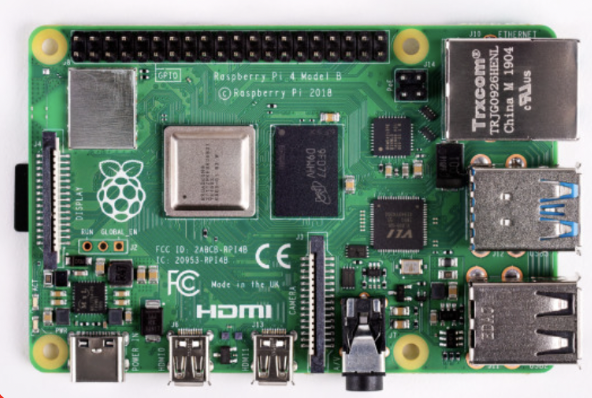
- Overview: The Raspberry Pi 4 is a powerful and versatile single-board computer known for its ability to run full operating systems and support various programming environments.
¶ Specifications
| Specification | Value |
|---|---|
| Operating Voltage | 5V |
| Power Consumption | Up to 3A |
| CPU | Quad-core Cortex-A72 (ARM v8) 64-bit, 1.5GHz |
| Memory | 1GB, 2GB, 4GB, or 8GB LPDDR4-3200 SDRAM |
| Connectivity | 2.4 GHz and 5.0 GHz IEEE 802.11ac wireless, Bluetooth 5.0, BLE |
| Interfaces | 2 × USB 3.0, 2 × USB 2.0, 2 × micro HDMI, GPIO, 3.5mm audio jack, CSI, DSI |
-
Advantages:
- Operating System: Capable of running full-fledged operating systems like Linux, which provides a rich development environment.
- Extensive Community Support: Benefits from a large community and a wide range of available software and hardware modules.
-
Disadvantages:
- Power Consumption: Requires significant power, which can be a limiting factor in battery-operated applications.
- Overpowered for Some Applications: The capabilities of the Raspberry Pi 4 may exceed the requirements for simpler control tasks, potentially leading to inefficiencies.
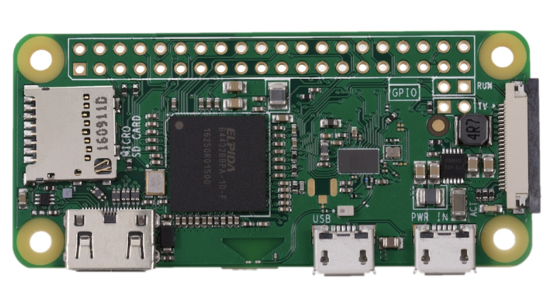
- Overview: The Raspberry Pi Zero W is a compact and less power-consuming version of the Raspberry Pi, featuring Wi-Fi connectivity and sufficient processing power for a variety of projects.
¶ Specifications
| Specification | Value |
|---|---|
| Operating Voltage | 5V |
| Power Consumption | 170mA (typical), 230mA (maximum) |
| CPU | Broadcom BCM2835 1GHz ARM11 core |
| Memory | 512MB LPDDR2 SDRAM |
| Connectivity | 2.4 GHz 802.11n wireless LAN, Bluetooth 4.1, BLE |
| Interfaces | Mini HDMI, USB On-The-Go, Micro USB power, HAT-compatible 40-pin header, Composite video and reset headers, CSI camera connector |
-
Advantages:
- Low Power Consumption: Consumes significantly less power than its more powerful counterparts, allowing the system to operate effectively with fewer battery requirements.
- Camera Module Compatibility: Direct support for the Raspberry Pi Camera Module makes it easy to implement visual monitoring systems.
-
Disadvantages:
- Reduced Processing Power: While it consumes less power, it also offers reduced processing capabilities, which may slow down complex computations.
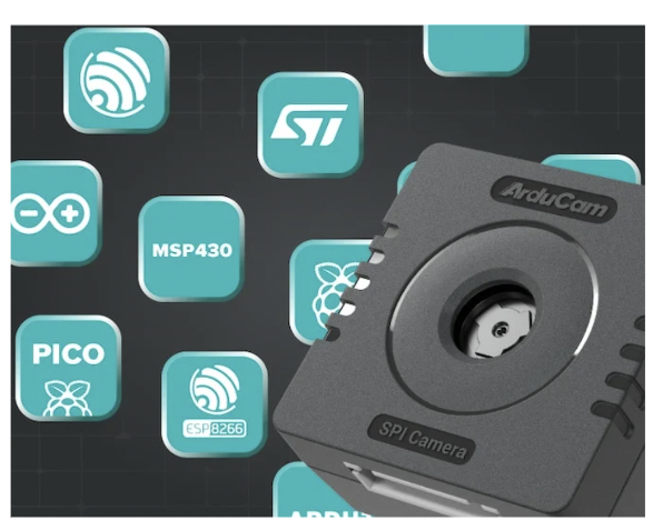
- Overview: Arducam is versatile and compatible with many microcontrollers, including STM32. It is known for its compact size and flexibility in connecting with various hardware.
¶ Specifications
| Specification | Value |
|---|---|
| Resolution | 5 megapixels |
| Video | 1080p at 30 frames per second |
| Sensor | OV5647 |
| Lens | Fixed focus |
| Field of View | 54 degrees horizontal |
| Interface | CSI |
-
Advantages:
- Flexibility: Can be easily connected to a wide range of microcontrollers, providing versatility across different platforms.
- Compact Size: Smaller than many comparable camera modules, making it suitable for space-constrained applications.
-
Disadvantages:
- Depth of Field: Less suitable for our specific application, with a shorter depth of field that may not provide the clarity required at varying distances.
- Integration Complexity: Requires additional configuration when used with non-native platforms, potentially complicating the setup and integration process.
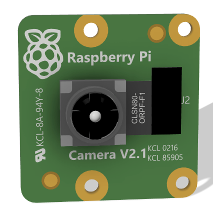
- Overview: The Raspberry Pi Camera V2 is widely used in various Raspberry Pi projects due to its high resolution and compatibility with all models of Raspberry Pi. It features an 8-megapixel sensor and supports 1080p video recording.
¶ Specifications
| Specification | Value |
|---|---|
| Resolution | 8 megapixels |
| Video | 1080p at 30 frames per second |
| Sensor | Sony IMX219 |
| Lens | Fixed focus, 3.04 mm focal length |
| Field of View | 62.2 degrees horizontal, 48.8 degrees vertical |
| Depth of Field | Approx 10 cm to infinity |
- Reason for Selection:
- Depth of Field: The camera's depth of field is suitable for our application, allowing clear focus from approximately 10 centimeters to infinity, which is ideal for monitoring and controlling the levitation process accurately.
- Ease of Integration: Direct compatibility with the Raspberry Pi platform facilitates straightforward integration with our system, utilizing existing libraries and software tools for rapid development.
- OS and Programming Compatibility: The ability to use an OS and program in Python on the Raspberry Pi enhances flexibility in developing more complex algorithms for control and image processing.
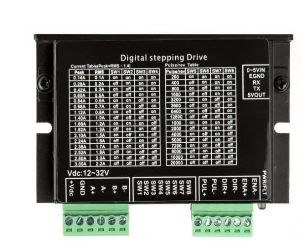
- Overview: The ACT DM430 is a robust motor driver commonly used in Robotics Practicals. It is designed for high precision and efficiency in motor control.
¶ Specifications
| Specification | Value |
|---|---|
| Operating Voltage | 20V to 50V |
| Output Current | 2.1A to 4.2A (peak) |
| Microstepping | Up to 256 microsteps per step |
| Input Signal | Pulse (DIR, PUL) |
-
Advantages:
- High Performance: Offers precise control and is capable of handling significant power requirements.
- Robustness: Designed for demanding applications, ensuring durability and reliability.
-
Disadvantages:
- Complexity and Cost: May be considered overkill for applications where no actual motor actuation is needed, adding unnecessary complexity and cost.
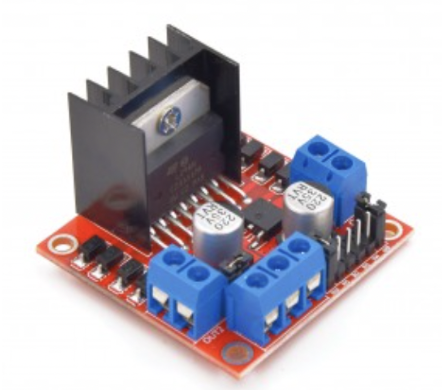
- Overview: The L297N motor driver, part of the Acoustic Levitation Kit, is simpler and specifically designed to provide sufficient power for applications like acoustic levitation.
¶ Specifications
| Specification | Value |
|---|---|
| Operating Voltage | 4.5V to 36V |
| Output Current | 2A per channel (continuous), 3A (peak) |
| Control Signal Voltage | 2.3V to 5V (high), 0.7V to 1.5V (low) |
| Power Dissipation | 25W |
- Reason for Selection:
- Simplicity: Offers straightforward functionality without the complexities of more advanced motor drivers.
- Adequate Power: Provides more than enough power for the transducers used in the acoustic levitation setup.
- Cost-Effectiveness: More cost-effective compared to high-end motor drivers, making it ideal for the specific needs of the levitator without overspending.
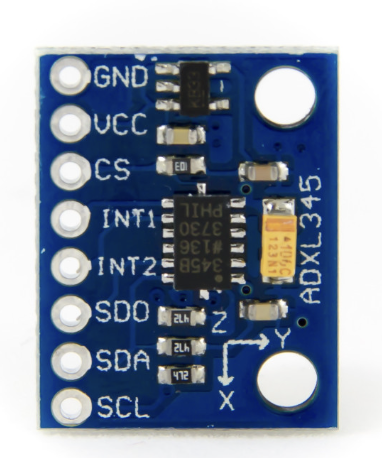
- Overview: The ADXL345 is a well-known accelerometer that has been previously used in the Nordend project. It is known for its ease of integration with microcontroller platforms like the Raspberry Pi.
¶ Specifications
| Specification | Value |
|---|---|
| Operating Voltage | 2.0V to 3.6V |
| Current Consumption | 40 μA (typical), 140 μA (maximum) |
| Measurement Range | ±2g, ±4g, ±8g, ±16g |
| Sensitivity | 256 LSB/g (±2g), 128 LSB/g (±4g), 64 LSB/g (±8g), 32 LSB/g (±16g) |
| Interface | I2C/SPI digital output |
-
Advantages:
- Proven Reliability: Its previous use in similar projects provides a reliable basis for its performance and expected stability.
- Easy to Interface: Offers straightforward connectivity with Raspberry Pi, which simplifies the setup process.
-
Disadvantages:
- Limited Advanced Features: While sufficient for basic applications, it may lack certain advanced features found in newer models.
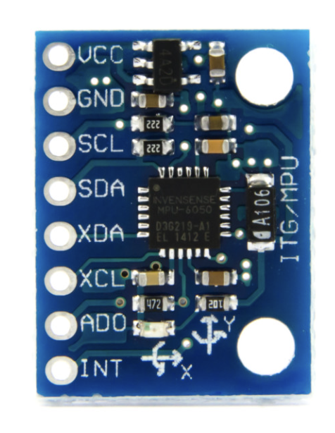
- Overview: The MPU 6050 was chosen as the accelerometer for this project after careful consideration of its specifications and the project needs.
¶ Specifications
| Specification | Value |
|---|---|
| Operating Voltage | 2.3V to 3.4V |
| Current Consumption | 500 μA |
| Measurement Range | ±2g, ±4g, ±8g, ±16g |
| Sensitivity | 16,384 LSB/g (±2g), 8,192 LSB/g (±4g), 4,096 LSB/g (±8g), 2,048 LSB/g (±16g) |
| Interface | I2C digital output |
- Reason for Selection:
- Suitability for Experimental Needs: Selected for its compatibility with the project's technical requirements and integration ease with other components.
- Cost-Effectiveness: Provides the necessary features at a cost-effective price point, balancing functionality and budget.
Description:
This is a 20W adjustable DC-DC buck converter module with a digital display, based on the LM2596 3A step-down voltage regulator. It supports an input of 0~40V DC with an accuracy of ±0.05V. This module includes a display for the output voltage readout and a screw potentiometer for adjusting the output voltage.
¶ Specifications
| Specification | Value |
|---|---|
| Input Voltage | 4.0 ~ 40V |
| Output Voltage | 1.25V ~ 37V |
| Output Power | 20W |
| Output Current | 3A (recommended up to 2A without heatsink) |
| Dimensions | 6.6 x 3.6 x 1.2 cm |
| Weight | 22g |
Features:
- Supports self-calibration for high-precision voltage output.
- Digital display for easy monitoring of input/output voltage.
- Touch button for switching between input and output voltage measurements.
- Easy-to-use wire terminals, no soldering required.
- High conversion efficiency, averaging 88%.
- Protections: reverse polarity, overheating, and short circuit.
Description:
This shield offers protection from overcharge and deep discharge, simple recharging via micro USB or USB Type-C, and outputs 5V via USB Type-A or solder pins, and 3V via solder pins. It features a side switch for power control and LED indicators for charge status.
¶ Specifications
| Specification | Value |
|---|---|
| Output Voltage | 5V (3A), 3V (1A) |
| Dimensions | 100.5 x 48.5 x 18 mm |
| Weight | 36g |
Features:
- Overcharge and deep discharge protection.
- Easy charging via micro USB or USB Type-C.
- Side switch for turning the output on/off.
- LED indicators for charge status.
- Direct output to USB and solder pins for both 5V and 3V outputs.
Description:
The MT3608 is a compact DC-DC boost (step-up) converter module capable of increasing input voltage from as low as 2V to as high as 24V. It is efficient, lightweight, and features an adjustable output voltage via a potentiometer. This makes it ideal for applications requiring a stable higher voltage from a lower voltage source, such as battery-powered systems.
¶ Specifications
| Specification | Value |
|---|---|
| Input Voltage | 2.0 ~ 24V |
| Output Voltage | 3V ~ 26V (adjustable via potentiometer) |
| Rated Current | 1A (continuous operation) |
| Peak Current | 2A (short term) |
| Efficiency | >93% |
| Dimensions | 37 x 17 x 7 mm |
| Weight | 4.5g |
Features:
- High conversion efficiency of over 93% under optimal conditions.
- Compact and lightweight design for easy integration.
- Adjustable output voltage via onboard potentiometer.
- Suitable for boosting the voltage of battery-powered devices.
- Simple wire terminals for easy connections.
- Overcurrent and thermal shutdown protections.
¶ Battery Selection and Power Calculations
¶ Power Consumption and Energy Calculations
| Device | Mode | Consumption (mA) | Operating Voltage (V) | Effective Power Consumption (W) | Time (h) | Energy Consumed (Wh) | Energy Consumed (Wh) with Contingency |
|---|---|---|---|---|---|---|---|
| Raspberry Pi Zero W | Idle | 110 | 5 | 0.625 | 8.000 | 5.000 | 6.000 |
| Raspberry Pi Zero W | Actuating Acoustic Levitation Device | 230 | 5 | 1.307 | 0.067 | 0.087 | 0.105 |
| L298N Motor Driver | Idle | 20 | 5 | 0.108 | 8.000 | 0.864 | 1.037 |
| L298N Motor Driver | Actuating Acoustic Levitation Device | 1500 | 5 | 8.065 | 0.067 | 0.538 | 0.645 |
| ADXL345 IMU Sensor | N/A | 1.23 | 5 | 0.007 | 8.000 | 0.056 | 0.067 |
| Raspberry Pi Camera V2 | N/A | 250 | 5 | 1.420 | 0.067 | 0.095 | 0.114 |
¶ Efficiency Considerations
When calculating the effective power consumption, the efficiency of the voltage regulators was taken into account.
¶ 20W Adjustable DC-DC Buck Converter
- Efficiency: 88%
- Devices: Raspberry Pi Zero W, ADXL345 IMU Sensor, Raspberry Pi Camera V2
The formula used to calculate the effective power consumption:
Example for Raspberry Pi Zero W in idle mode:
\text{Effective Power Consumption} = \frac{0.55 \text{W}}{0.88} = 0.625 \text
¶ Purecrea MT3608 Step-up Voltage Regulator
- Efficiency: 93%
- Devices: L298N Motor Driver
The formula used to calculate the effective power consumption:
Example for L298N Motor Driver in idle mode:
\text{Effective Power Consumption} = \frac{0.1 \text{W}}{0.93} = 0.108 \text
¶ Total Energy Consumption and Battery Selection
¶ Total Energy Consumption
Based on our detailed power consumption and energy calculations, the total energy usage for the system is as follows:
- Raspberry Pi Zero W (Idle): 6.00 Wh over 8 hours
- Raspberry Pi Zero W (Actuating): 0.105 Wh over 4 minutes
- L298N Motor Driver (Idle): 1.037 Wh over 8 hours
- L298N Motor Driver (Actuating): 0.645 Wh over 4 minutes
- ADXL345 IMU Sensor: 0.067 Wh over 8 hours
- Raspberry Pi Camera V2: 0.114 Wh over 4 minutes
Total Energy Usage with 20% Contingency:
6.00 + 0.105 + 1.037 + 0.645 + 0.067 + 0.114 = 7.968 \text
¶ Battery Selection
We have chosen to use two 18650 Li-ion battery cells for powering the system. The specifications for these batteries are as follows:
- Number of Cells: 2
- Battery Voltage: 3.7V per cell
- Battery Capacity: 3000mAh per cell
- Total Battery Capacity: 3000mAh (since the batteries are in series)
- Total Voltage: 3.7V 2 = 7.4V
¶ Total Energy Available
The total energy available from the battery pack can be calculated as:
= \text
= = Wh
¶ Safety Margin
The safety margin is the difference between the total energy available and the total energy usage. This ensures that the system will have enough power to operate effectively under all conditions.
\text{Safety Margin (Wh)} = 22.2 \text{ Wh} - 7.968 \text{ Wh} = 14.232 \text
¶ Conclusion
Based on the calculations:
- The total energy consumption of the system, including a 20% contingency, is approximately 7.968 Wh.
- The selected battery pack provides a total energy of 22.2 Wh.
- The safety margin is 14.232 Wh, which indicates that the battery pack is sufficient to meet the system's energy demands.
This safety margin ensures that the system will remain operational throughout its required time, even accounting for potential inefficiencies and unexpected power draws.
¶ Design Choices : Software
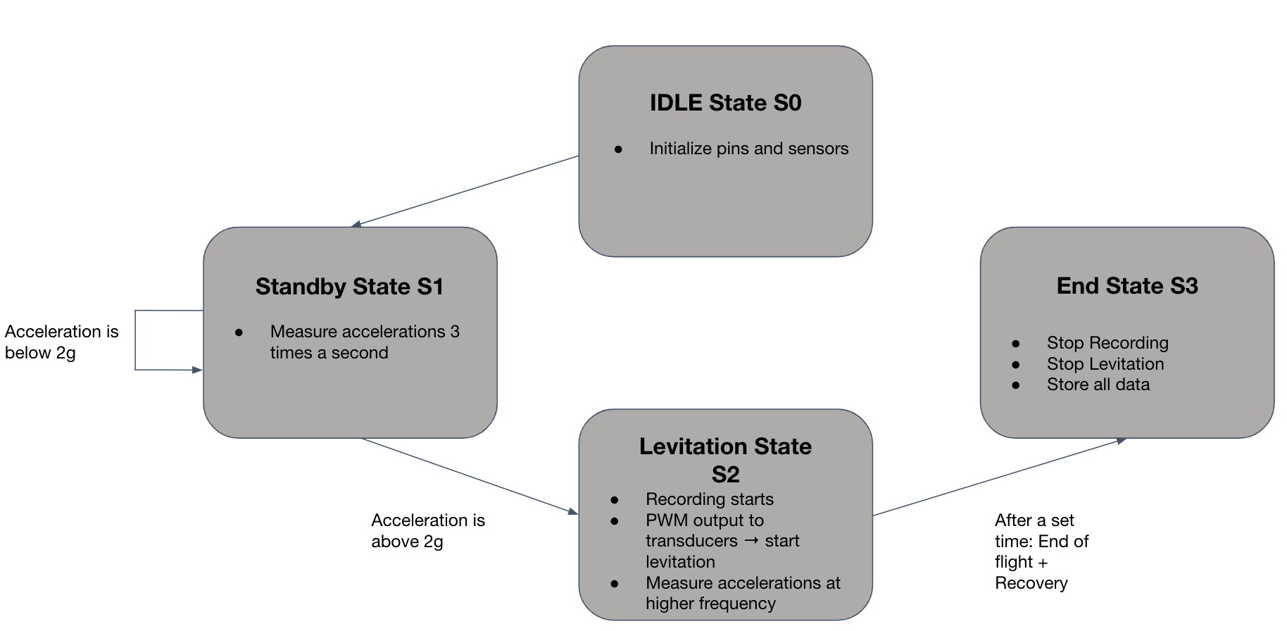
The software architecture for our levitation system is based on a Finite State Machine (FSM) design. This approach ensures that the system operates in a controlled and predictable manner, transitioning between predefined states based on specific conditions. The code architecture is inspired by previous successful implementations in projects like Nordend and Wildhorn.
¶ FSM States and Components
¶ 1. IDLE State S0
- Purpose: Initialize system components.
- Actions:
- Initialize pins and sensors.
- Prepare the system for subsequent operations.
- Transition: Moves to Standby State S1 after initialization is complete.
¶ 2. Standby State S1
- Purpose: Monitor system conditions and prepare for activation.
- Actions:
- Measure accelerations at a rate of 3 times per second.
- Transition:
- If acceleration is below 2g, remain in Standby State.
- If acceleration exceeds 2g, transition to Levitation State S2.
¶ 3. Levitation State S2
- Purpose: Activate the levitation mechanism and record data.
- Actions:
- Start recording data.
- Provide PWM output to transducers to initiate levitation.
- Measure accelerations at a higher frequency to ensure stability.
- Transition: Move to End State S3 after a predetermined duration or upon receiving a specific signal indicating the end of the flight.
¶ 4. End State S3
- Purpose: Safely conclude operations and store data.
- Actions:
- Stop recording data.
- Cease levitation activities.
- Store all collected data for post-flight analysis.
- Transition: System remains in End State until manually reset or powered off.
¶ Components Involved
- Raspberry Pi Zero W: Acts as the central processing unit, executing the FSM and controlling other components.
- ADXL345 IMU Sensor: Measures acceleration in all three axes, providing critical data for state transitions.
- Camera (v2 Raspberry Pi): Captures visual data during levitation.
- LEDs: Indicate the current state of the system visually and provide sufficient lighting for filming the levitating particle.
- Motor Driver: Controls the transducers, providing the necessary PWM signals for levitation.
- Buzzer: Provides audible feedback during state transitions or critical events.
¶ System Context
- Design Architecture: The preliminary design architecture mirrors successful strategies from previous projects (Nordend and Wildhorn), ensuring reliability and efficiency.
- Code Similarity: Leveraging proven code structures from these projects minimizes development time and increases system robustness.
This FSM-based design provides a structured and efficient way to manage the complex interactions between various components in the levitation system, ensuring that each action is performed at the correct time and under the appropriate conditions.
¶ Relevant Documents
-
STMicroelectronics, 2023
STM32G474RE Datasheet
Available at: STMicroelectronics -
Raspberry Pi Foundation, 2023
Raspberry Pi 4 Model B Datasheet
Available at: Raspberry Pi -
Raspberry Pi Foundation, 2023
Raspberry Pi Zero W Datasheet
Available at: Raspberry Pi -
Arducam, 2023
Arducam OV5647 Camera Module Datasheet
Available at: Arducam -
STMicroelectronics, 2023
L298N Datasheet
Available at: STMicroelectronics -
Analog Devices, 2023
ADXL345 Datasheet
Available at: Analog Devices -
InvenSense, 2023
MPU-6050 Datasheet
Available at: InvenSense -
DigiKey, 2023
20W Adjustable DC-DC Buck Converter Module Datasheet
Available at: DigiKey -
Digitec, 2023
18650 Shield Battery Module Datasheet
Available at: Digitec
- 2024_C_SE_PL_ACOUSTIC_LEVITATION_EXPERIMENT_01 Declaration of purpose
The payload shall consist of an experiment that will use acoustic levitation to maintain a lightweight body in levitation from liftoff and for the longest duration possible. - 2024_C_SE_PL_ACOUSTIC_LEVITATION_EXPERIMENT_02 Avionics
The payload shall use its own set of avionics that is independent from the main rocket avionics boards. - 2024_C_SE_PL_ACOUSTIC_LEVITATION_EXPERIMENT_03 Data collection
The payload shall store and log all collected data on its own avionics. - 2024_C_SE_PL_ACOUSTIC_LEVITATION_EXPERIMENT_04 Data storage
All data gathered by the camera shall be stored in a 'black box' designed by AV. - 2024_C_SE_PL_ACOUSTIC_LEVITATION_EXPERIMENT_05 Status indicator
The payload shall indicate visually and auditorily whether it is on or off. - 2024_C_SE_PL_ACOUSTIC_LEVITATION_EXPERIMENT_06 Mass
The payload mass shall be between [3000]g and [3990]g. - 2024_C_SE_PL_ACOUSTIC_LEVITATION_EXPERIMENT_07 Volume
The payload shall fit within a [30]x[10]x[10]cm volume. - 2024_C_SE_PL_ACOUSTIC_LEVITATION_EXPERIMENT_08 Structure
The payload shall include its own internal or external structure. - 2024_C_SE_PL_ACOUSTIC_LEVITATION_EXPERIMENT_09 Structure load case
The payload structure shall protect the experiment from axial accelerations loads of at least [60]g's. - 2024_C_SE_PL_ACOUSTIC_LEVITATION_EXPERIMENT_10 Structure load case
The payload structure shall protect the experiment from radial accelerations of at least [3]g's. - 2024_C_SE_PL_ACOUSTIC_LEVITATION_EXPERIMENT_11 Restricted materials
The payload shan't contain any hazardous material such as lead or radioactive elements. - 2024_C_SE_PL_ACOUSTIC_LEVITATION_EXPERIMENT_12 Payload assembly
The payload structure shan't be inextricably connected to other rocket components than the payload supporting structure. - 2024_C_SE_PL_ACOUSTIC_LEVITATION_EXPERIMENT_13 Assembly human needs
The assembly of the payload shall require at most [2] person. - 2024_C_SE_PL_ACOUSTIC_LEVITATION_EXPERIMENT_14 Operation human needs
The operation of the payload shall require no more than [1] person. - 2024_C_SE_PL_ACOUSTIC_LEVITATION_EXPERIMENT_15 Power source
The payload shall be self-powered both on the pad and in-flight. - 2024_C_SE_PL_ACOUSTIC_LEVITATION_EXPERIMENT_16 Autonomy
The payload power source shall have an autonomy of at least [8] hours (with the payload possibly running on 'standby mode' for most of that time). - 2024_C_SE_PL_ACOUSTIC_LEVITATION_EXPERIMENT_17 Budget
The development and construction of the payload shan't cost more than [600]CHF. - 2024_C_SE_PL_ACOUSTIC_LEVITATION_EXPERIMENT_18 Experiment acceleration resistance
The payload experiment shall function when subjected to vertical accelerations of at least [8]g's. - 2024_C_SE_PL_ACOUSTIC_LEVITATION_EXPERIMENT_19 Experiment acceleration resistance
The payload experiment shall function when subjected to radial accelerations of at least [3]g's. - 2024_C_SE_PL_ACOUSTIC_LEVITATION_EXPERIMENT_20 Experiment recording
The payload should include a small camera that can record the experiment. - 2024_C_SE_PL_ACOUSTIC_LEVITATION_EXPERIMENT_21 Assembly time
Assembly of the payload in the launch vehicle shan't take more time than [10]min.
- 2024_C_SE_REQ_01 LV declaration of purpose
The LV shall be a mean of testing spaceshot technologies and participate in the L9 flight category at the 2025 EuRoC competition ([9000]m apogee).