¶ Introduction
¶ Purpose
This document presents the design of the second event trigger board for the FHI rocket. The trigger board’s primary role is to activate the pyro cutter at the correct altitude during descent.
¶ Definitions and Abbreviations
REMOVE THIS TEXT
Make a list of abreviations and technical vocabulary which you use in the document, then give a definition for each abbreviation, word, ...
REMOVE THIS TEXT
- Second Event: Unreefing of the parachute during descent.
¶ Applicable and Reference Documents
- 2024_C_RE_SECOND-EVENT-TRIGGER_DJF
- 2024_C_RE_TRIGGERBOARD_LIFT_TSP
- 2024_C_RE_TRIGGERBOARD_LOW_TEMP_TSP
- 2025_C_RE_TRIGGERBOARD_OP
¶ Iterations
Originally, the board was designed following Maxime Leriche's semester project, it was based on the STM32 architecture and programmed in C with custom libraries (it is recommended to skim through it to understand some of what will be said next). However, during the testing phase of the code and especially the libraries, many things went wrong and development was almost at a standstill. A prototype was never made of this version.
Instead, It was determined that simplifying the code by using community made libraries and a simple state machine would speed up development time considerably. And so, the next 4 versions were programmed using the Arduino IDE.
¶ V1
(Missing 3D models of the Adafruit microsd card bff breakout and the Adafruit LPS22 breakout)
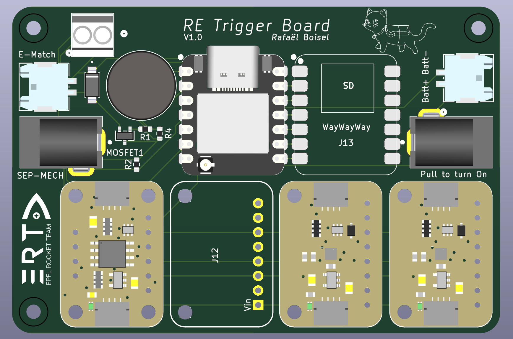
V1 was designed for the first Test Flight. It is based on the ESP32 architecture with the Seeed Studio Xiao ESP32 S3, chosen because of its computing power, compact size and included usb-c connector. It was designed to be modular, cheap(2 layer) and with the least amount of custom circuitry which makes it a rather large PCB at 85x57mm.
From left to right, you can find a molex connector to connect a Lipo pouch cell used exclusively to ignite the e-match and the screw terminal used to connect said e-match. Next to that is the "sep-mech" barrel jack which detects the opening of the parachute (the parachute pulls the plug which closes the switch in the jack sending a signal to a GPIO on the Seeed) and the mosfet circuitry used to blow the e-match when a signal is sent from the Seeed.
The round component is a buzzer used to signal to the user if the initialization of the board was succesfull and next to it is the MCU (Seeed).
The blank pad next to it is the SD Card Holder (ps: the "WayWayWay" marking saves some cost when ordering the pcb) and to the right there is another molex connector and barrel jack. These are used for powering the board. The connector is used for another pouch cell while the jack is used as a ON/OFF switch.
Finally the 4 large breakouts are 3 barometers (2 BMP390s and 1 LPS22) and an EEPROM. Why not use 3 BMPs ? Well the BMP390 only supports two adresses on the same I2C line and the ESP32 S3 only has a single line. To respect the requirements, a third barometer of a second type was added. The EEPROM holds important flight data like the current state to be able to seemlessly keep the code running in case of an in-flight restart.
While this version actually worked during the Test Flight, it had several flaws.
First, the two batteries were bulky, and more importantly did not respect the rules published by EUROC.
Second, the opposite facing jacks made the battery jack a pain to access once the PCB was wrapped up inside the parachute.
Third, the boot button on the Seeed that was hijacked to be used as a user button was very hard to reach.
Fourth, the footprint for the mosfet used was wrong and so wire wrapping had to be performed on the PCB to make it functional (check this everytime because it is a headache to diagnose).
Fifth, it was thought that the jacks were a weak point and risked being ripped off.
¶ V2 and V3
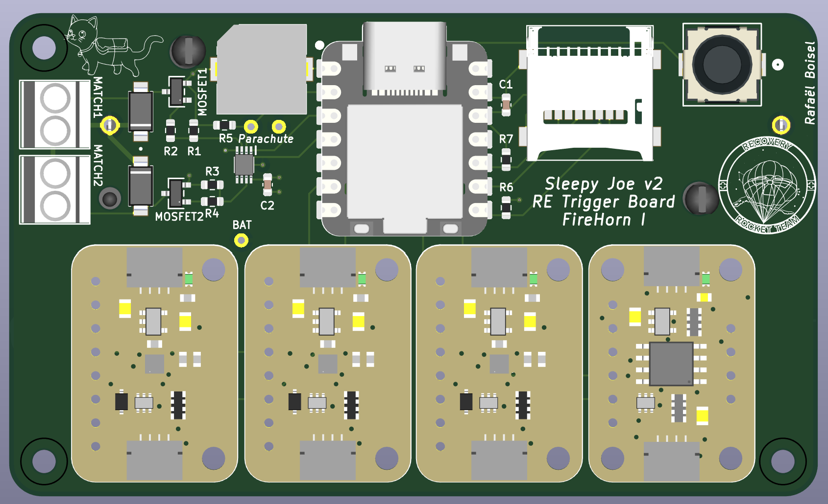
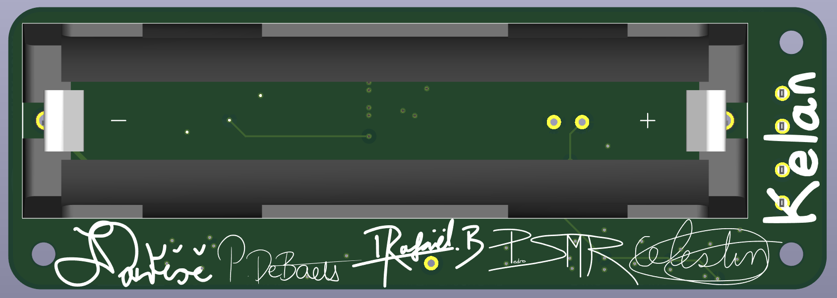
V2 and V3 were designed and ordered at the same time. The only differences between them was that V2 kept the sensor and eeprom breakout boards and V3 has an added status LED and KX134 accelerometer (for more datalogging). Both were now 4 layer boards with sizes of 87x52mm and 87x30mm respectively.
Changes from V1 are: an added tactile button, pouch cells replaced by a single 18650 Li-ion cell, a vibration resistant sd card holder, a lower profile buzzer, the possibility to ignite two separate e-matches, through hole jacks being replaced by wall mounted jacks, fixed mosfet footprint, the addition of and AND gate to mechanically prevent the MCU misfiring the e-matches (the two signals the gate has to receive are the MCU signal and the parachute deployment detection signal), and most importantly the MCU itself.
The ESP32 S3 was replaced by the Seeed Studio Xiao RP2350 because of its two separate I2C lines (allowing 3 BMP390s on the board), its larger amount of GPIOs, and its built-in battery voltage measuring circuit.
In the end, V2 was never assembled and V3 flew on a second Test Flight. This time around though, the flight was a failure. One board turned off midway throught the flight and never ignited its e-match because the wall-mounted jacks' connections to the PCB (wires reinforced with shrink tape) were too flimsy and the second one, although it survived the flight had an erroneous code uploaded to it...
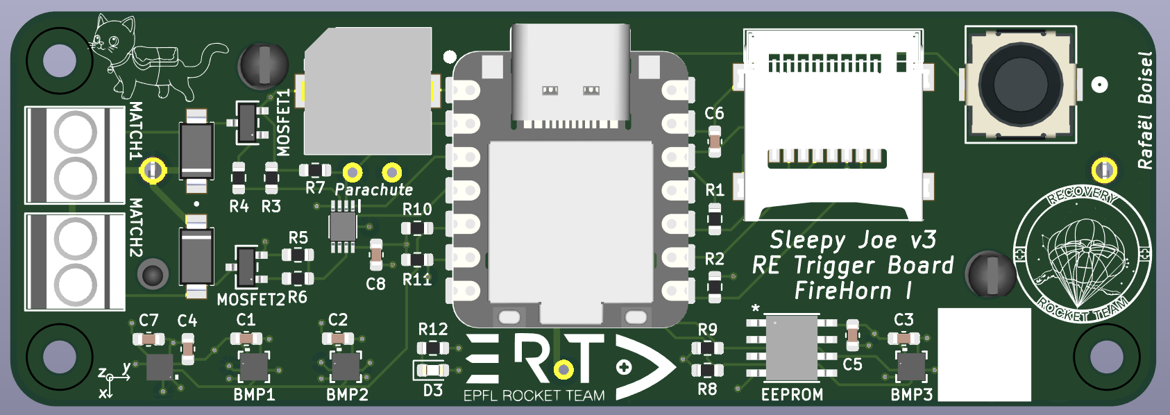
¶ VF
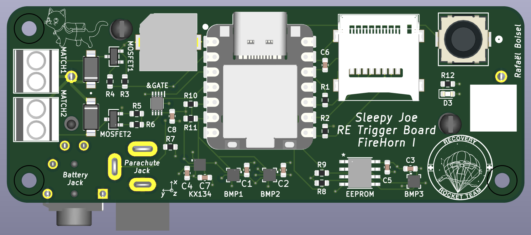
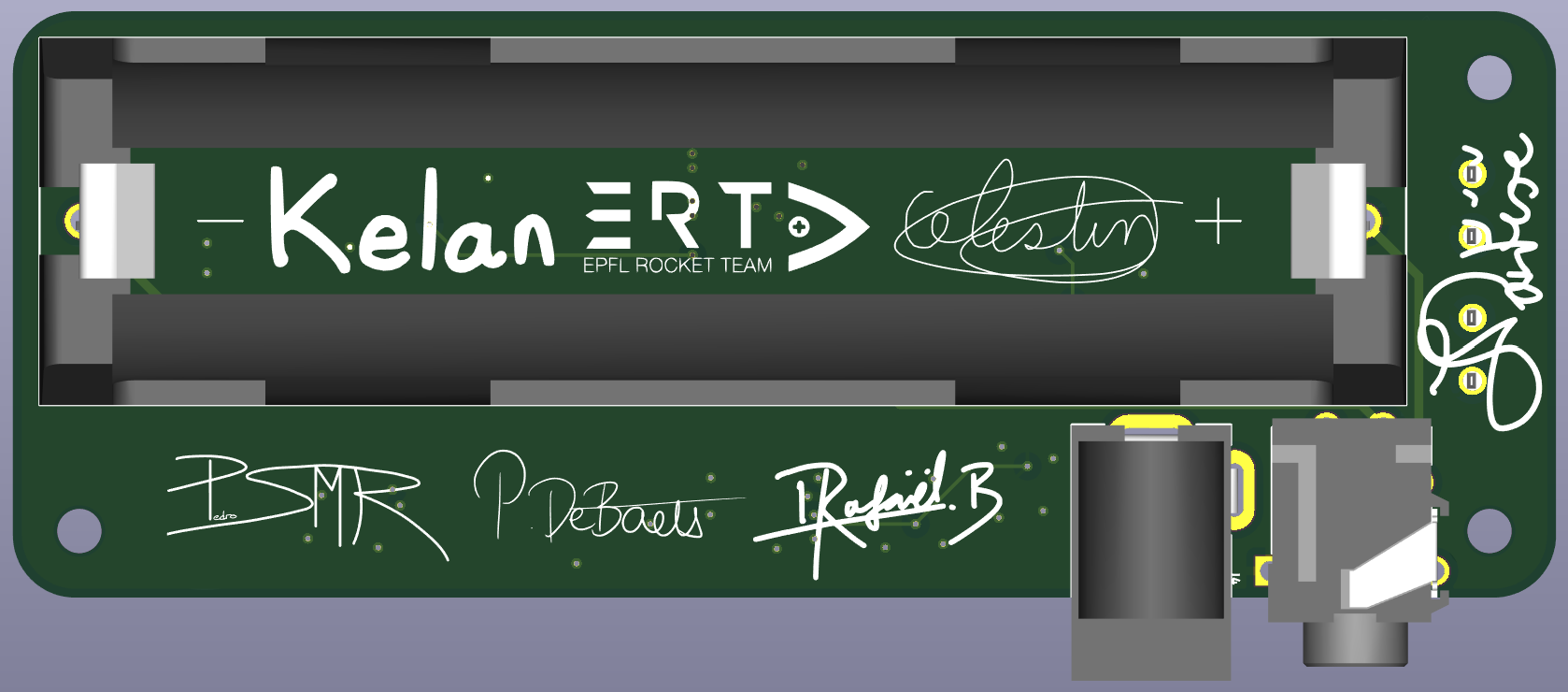
The final version of the trigger board is a 87x33mm 4 layer pcb. It is almost identical to V3 but facilitates operations and assembly greatly by going back to the through hole jacks.
As of writting this document, it has flown as part of a parachute test and completed its mission.
¶ Functional Description
The trigger board’s primary role is to activate the pyro cutter at the correct altitude during descent. To achieve this, its MCU monitors altitude using three barometers and controls a transistor circuit to deliver power to an e-match at the appropriate time. The board also includes datalogging capabilities via an SD card, recording key parameters such as battery voltage, barometer readings, accelerometer data, and internal code variables. To ensure robustness against temporary power losses, an EEPROM is used to store essential flight and state machine variables, allowing the system to resume operation seamlessly. Finally, since the trigger board is integrated into the rocket early in the assembly process, it also incorporates accessibility and user-interaction features to facilitate setup and handling.
¶ Function Tree
¶ BOM
The BOM can be found in the EPFL Rocket Team's Drive.
For each component, it includes : its reference in the schematics, a link to a store where the datasheet can also be found and how many are needed for one and two boards and a very short description of why they were chosen (other than electrical compatibility)
¶ Schematic
The Kicad schematic can also be found in the Drive.
Contains some calculations that led to design choices.
¶ 3D
A STEP file of the assembled board can also be found in the Drive
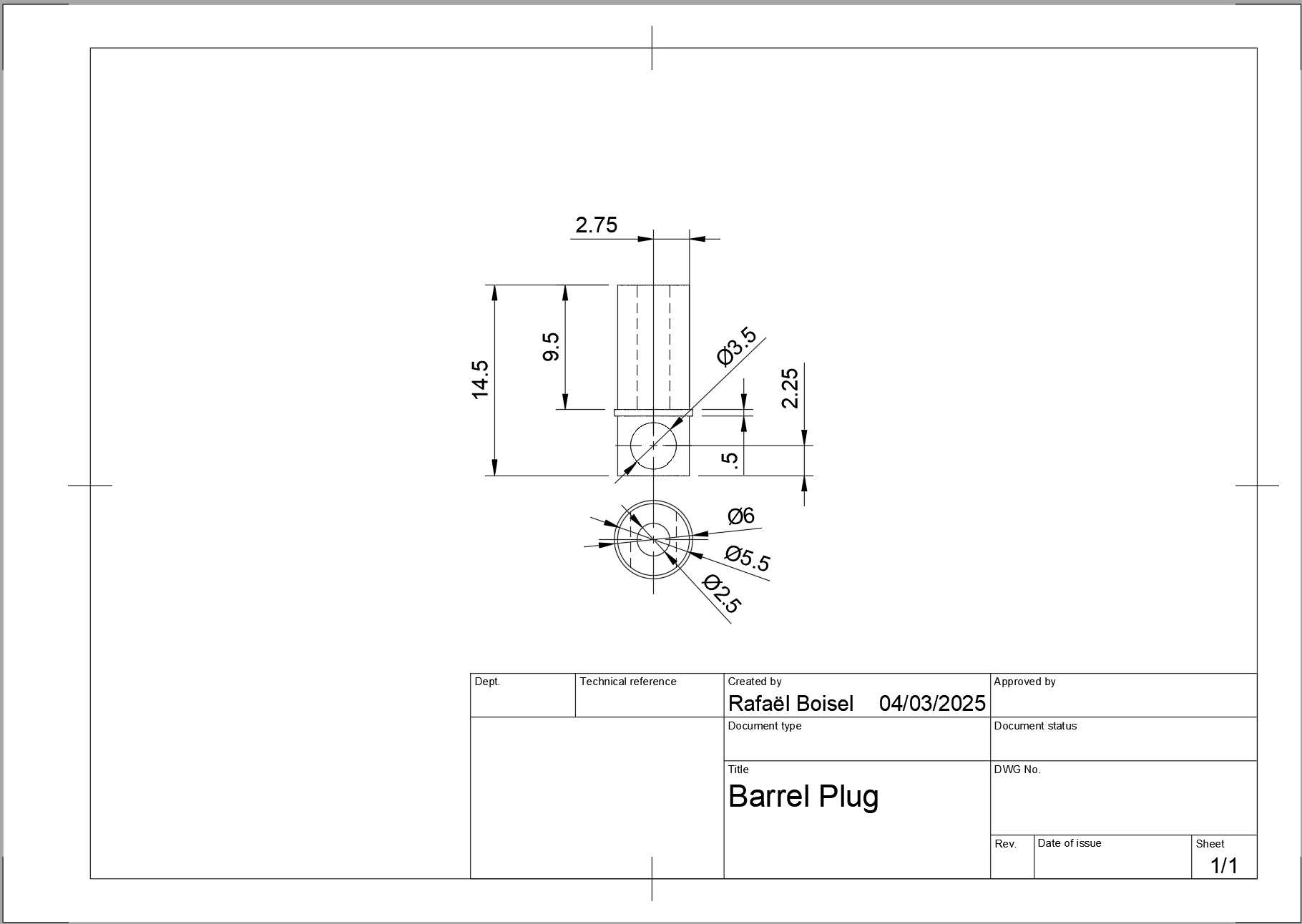
¶ Custom Barrel Plug
¶ Description
| Part Name | Number of Parts | Link to STEP file |
|---|---|---|
| Barrel PLug | x2 | Barrel Plug.step |
This plug is linked to the parachute and plugged into the parachute deployment detection jack. When the parachute deploys, is pulls the plug and deployment is detected.
¶ Technical Drawings
¶ Code
The fully commented code can be found in the EPFL Rocket Team's Github.
In it's first iterations, the code was written in C in the STM32CubeIDE following a previous semester project's structure. Libraries for each sensor we're written by hand and RTOS and multi-threading we're used to parallelize tasks like data acquisition and logging.
At some point during development, it was found that the hand made libraries we're too error prone and unreliable and so it was decided to switch to the Arduino IDE with open source, pre-written libraries. The logic was also simplified to a simple state-machine. This boosted development speed by a huge margin and allowed for topics like reliability, precision and optimization to be addressed.
While the code is functional, there are some unused features already baked in and certainly a rewrite or at least a refactor could reduce loop run time and clarity. For example a watchdog style timer was implemented to perform the second event when it reached 0 as a sort of failsafe (but needed a precise flight time to be activated), and the 2 sensor failure safeguard wasn't fully implemented. Finally, the eeprom default value check is very error prone and should be changed if kept in future iterations.
A flow chart the code is found below
¶ Design Constraints
¶ Constraints for Production
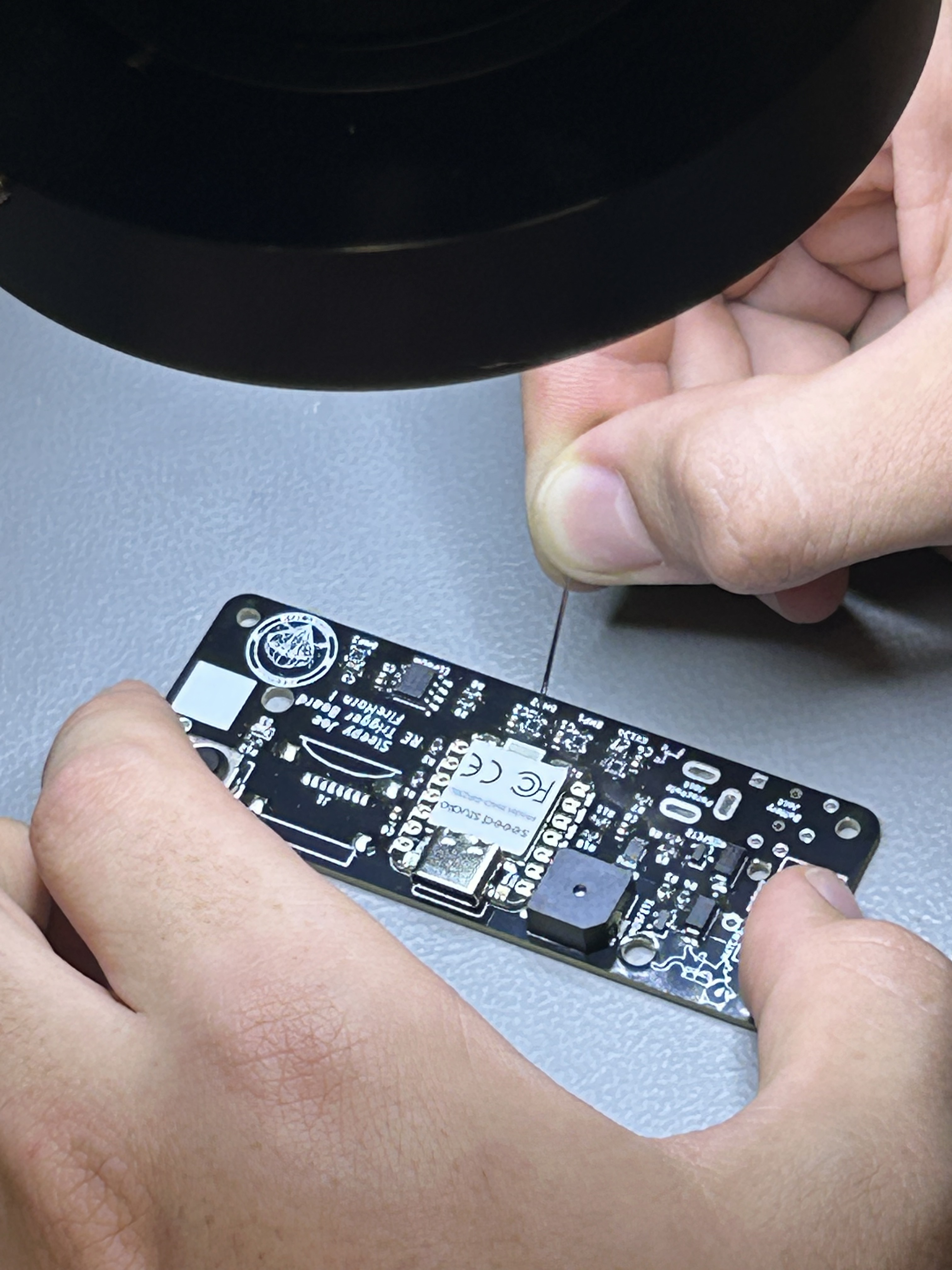
Assembly of all components par the jacks, the battery holder and screw terminals are done using a reflow oven. Application of the soldering paste on the sensor pads (even using a stencil) is difficult and may require the use of a high-tech technique i.e. using a sewing needle and a microscope to manually move soldering paste droplets to the small pads.
¶ Constraints for Operation
The SD card is constantly being written to (shown by the flashing of the LED on the Seeed). To avoid any SD card corruptions, it is advised to hold the user button down any time power needs to be cut as it stops the code writing to the SD card.
Having the Seeed plugged in through USB-C while the battery is inserted and the power plug is pulled out has never been tested and is not recommended.
Be very careful about reverse polarity because there is no protection circuit (put the battery in the right way !!!!!).