¶ Introduction
Firehorn coupling systems design was performed as a semester project and its process is extensively detailed in its associated semester project report.
¶ Definitions and Abbreviations
- CFRP: Carbon Fiber Reinforced Polymer
- RE: Recovery
- Li: Length of thread engagement
- Lk: Screw free length (distance between screw head base and engaged threads)
¶ Relevant Knowledge Needed
Following considerations were critical for the design process of the couplers:
- Nordend (2023) → heavy, complex (machining and operations), grip during assembly → avoid threaded coupling → modules assembly with screws for Firehorn and beyond
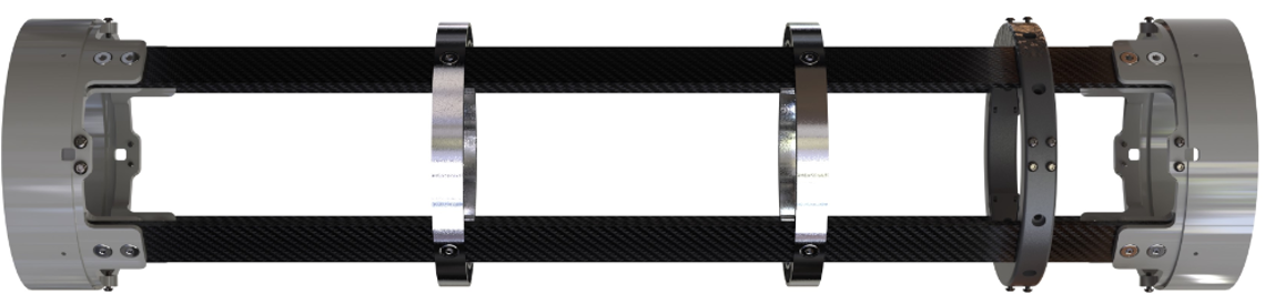
- Rocket structural philosophy same as Nordend: ears with CFRP rods and covering panels
- Compatibility must be possible with all current and future potential types of interfaces → flexibility
-- Reference design = rods/rods modules
-- Tank/rods → thermal compatibility (-183°C inside tank)
-- Tube (glued)/rods
-- Tube/tube (glued/glued), not in Firehorn
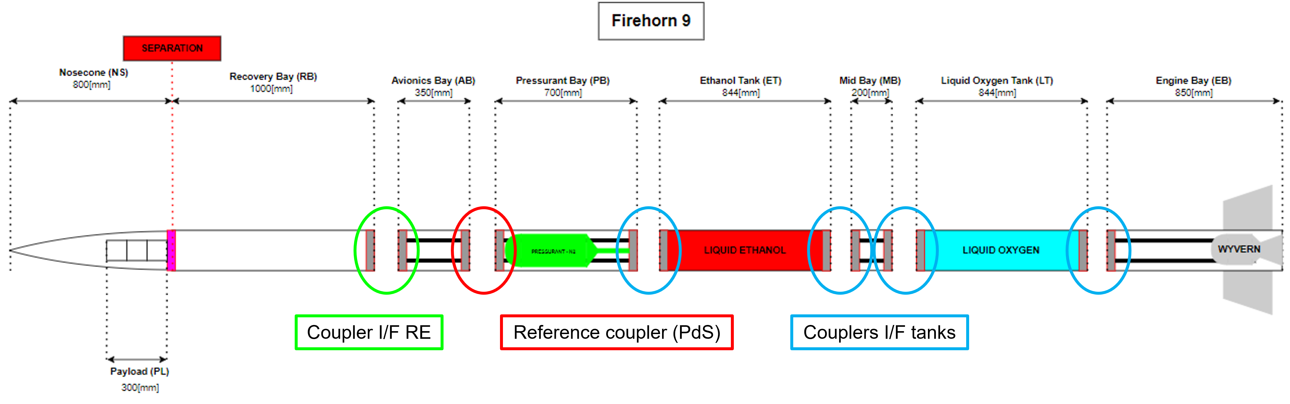
- 2024_C_SE_ST_COUPLER_REQ_01 Coupler declaration of purpose
The CPLRs shall structuraly connect two distinct parts of the LV. - 2024_C_SE_ST_COUPLER_REQ_02 Outside coupling
The CPLRs shall be assembled without accessing the inside of the LV. - 2024_C_SE_ST_COUPLER_REQ_03 Compatibility with the internal structure
The CPLRs shall be compatible with the rocket architecture (e.g. use of non structural panels as fairing & CFRP rods as structural elements) and other interfaces. - 2024_C_SE_ST_COUPLER_REQ_04 Compatibility with nearby temperatures
The CPLRs shall accommodate thermal stresses & unscrewing phenomenon due to neighbouring temperatures as low as [-180]°C. - 2024_C_SE_ST_COUPLER_REQ_05 Mass
The whole CPLR's assembly shall weigh less than [800][+/-200]g. - 2024_C_SE_ST_COUPLER_REQ_06 Integration diameter
The CPLR's integration diameter, usable for the passage of modules, shall be at least [160]mm. - 2024_C_SE_ST_COUPLER_REQ_07 Mechanical axial loads
The CPLRs shall resist axial parachute deployment loads of [30]g with an additional FoS of [3]. - 2024_C_SE_ST_COUPLER_REQ_08 Mechanical bending loads
The CPLRs shall resist bending moments caused by the fins of up to [4500]Nm with an additional FoS of [2]. - 2024_C_SE_ST_COUPLER_REQ_09 Integration time
The time needed to assemble 2 CPLRs with eachother without any torque-tightening manipulation shall be less than [3]min. - 2024_C_SE_ST_COUPLER_REQ_10 Integration time with tightening
If applicable, the time needed to assemble 2 CPLRs with eachother with torque-tightening manipulation shall be less than [6]min. - 2024_C_SE_ST_COUPLER_REQ_11 Tools required for assembly
Assembly of the CPLRs should only require common tools. - 2024_C_SE_ST_COUPLER_REQ_12 Tightening torque required for assembly
If applicable the tightening torque required to assemble the CPLRs shall be less than [150]Nm. - 2024_C_SE_ST_COUPLER_REQ_13 Post-assembly angular alignment
The circular angular difference between two structural rods on either end of a CPLR pair shall be less than [1]° after assembly. - 2024_C_SE_ST_COUPLER_REQ_14 Wear and fatigue
The CPLRs shall withstand between [100-1000] assembly/disassembly cycles while remaining operational. - 2024_C_SE_ST_COUPLER_REQ_15 Assembly steadiness
Both ends of the CPLRs shall not rotate relative to each other during assembly. - 2024_C_SE_ST_COUPLER_REQ_16 Implementation of coupling tubes
Airframe joints which implement "coupling tubes" should be designed such that the coupling tube extends no less than one body calibre (1D) on either side of the joint — measured from the separation plane. - 2024_C_SE_ST_COUPLER_REQ_17 Ease of machining
The CPLR parts shall be machined with conventional machining processes in EPFL workshops (e.g. ATME) using standard procedures. - 2024_C_SE_ST_COUPLER_REQ_18 Impermeability
The CPLR shall be IP54 compliant.
¶ Design Options
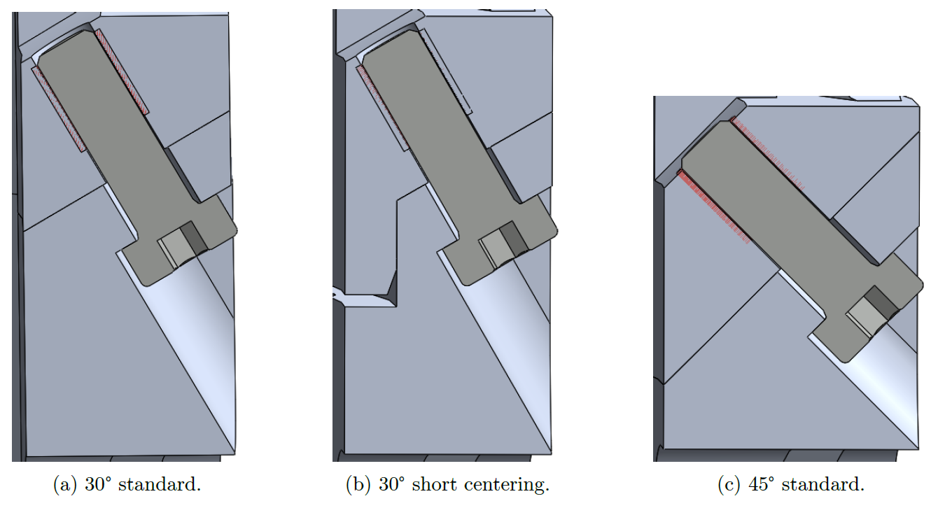
An outside screwing coupling system (called radax) was chosen to meet operations & interfaces flexibility needs. Considering all the iterations (see semester project report, Sect. 8), there are currently 3 radax design options: 30° and 45° options without short centering and a 30° option with short centering.
The main concern with such design is about the coaxiality that can be achieved with low angle conical interface. As there are 6 coupling locations, it may induce a curved rocket. Currently, the main solution to guarantee sufficient coaxiality would require the addition of a short centering feature with H7/js6 tolerances. However, as its centering diameter is around 170 [mm], costs increase (12 parts) may not be sustainable.
An overview of the design options is presented below.
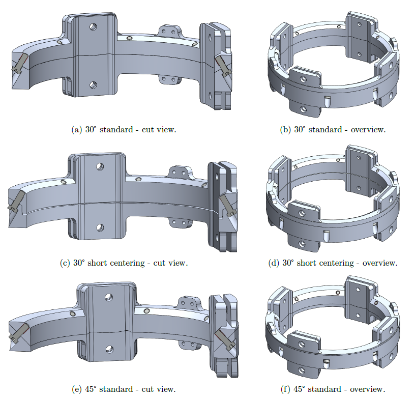
A summary of their advantages/disadvantages and their specifications are shown in the table below.
| Option | Mass (male/female) [g] | [mm] | Height [mm] (ears excl.) | Advantages | Disadvantages |
|---|---|---|---|---|---|
| 30° standard | 1040 (390/650) | 170 | 34 | High integration diameter | Poorest coaxiality |
| 30° short centering | 1035 (425/610) | 170 | 34 | Greatest coaxiality, high integration diameter | Manufacturing (tolerances) cost |
| 45° standard | 990 (435/555) | 164 | 26 | Most balanced and efficient use of material between male/female parts more compact/lightest, enhanced self-centering capabilities compared to 30° standard | Screws less used in traction, very high preload to prevent slip (rotation) |
The 3 design options all share these same characteristics:
- Material: Al 6082-T6
- Ears: as their design is not completed yet by internal structure members, their dimensions were approximated to the worst-case. In addition, they do not reflect the number of screws and their configuration.
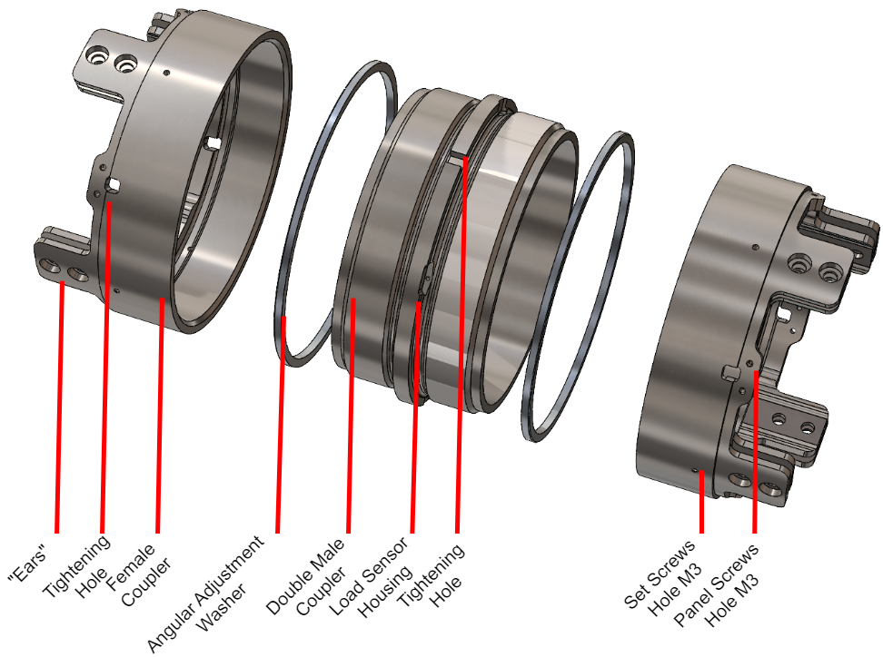
- Panel mounts:
– 4 M3x6 screws, undetermined type yet
– Li = 1D = 3 [mm]
– Lk = 1D = 3 [mm]- Coupling screws: 45° pattern between each (22.5° away from ears midplane)
– 8 M5x16 hex socket head cap screws with low head (10.9)
– Li = 1.5D = 7.5 [mm] (use of HELICOIL®)
– Lk = 8.5 [mm] with Lk,− = 5 [mm] (thickness of female part under screw head)
Screw plus tapping being the best way to secure bolted assemblies (especially compared to screw plus nut), the use of screw thread inserts (HELICOIL®) was considered. Yet, as one deals with aluminum parts, it is necessary to use these helical inserts to prevent damage to the aluminium tapping (seizing) since about 100 screwing/unscrewing cycles are planned. In addition, it better distributes the loads along the threads & reduces thread friction (which reduces the screw torsion).
A change in the integration diameter requirement during the project enabled the 45° option, which compared to 30° options provides the most balanced and efficient use of material for a radax system, beneficial for loads distribution. In addition, it is also the lightest option that may satisfy the mass requirement depending on final ears design and with theoretical enhanced self-centering capabilities. However, due to its higher angle, the screws are less used in traction and would require a higher preload to prevent slip.