¶ Goal(s) of the study
This document aims to present the method used to analyse with finite elements software the standard male coupler of the Firehorn rocket. Indeed, it is subjected to important loads during the flight, especially at the opening of the parachute.
¶ 214202_coupler_male_standard
¶ Geometry
The couplers are made of only one part, manufactured in 2050-T84 aluminum alloy. Below is an image of the standard male coupler.
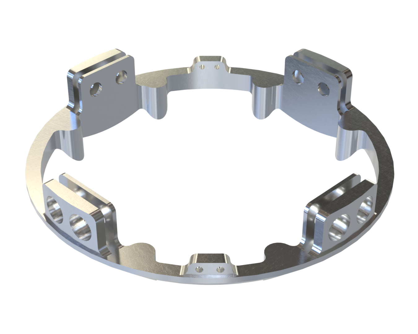
¶ Function
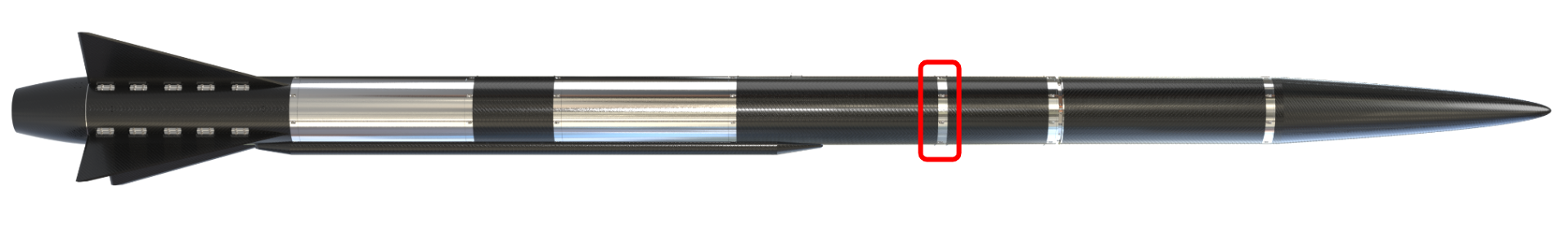
The male coupler’s function is to link the different modules of the Firehorn Rocket and resist the different forces applied to the structure while letting different cables and tubes pass through it. The standard male coupler is found at the bottom of the avionics bay.
¶ Material
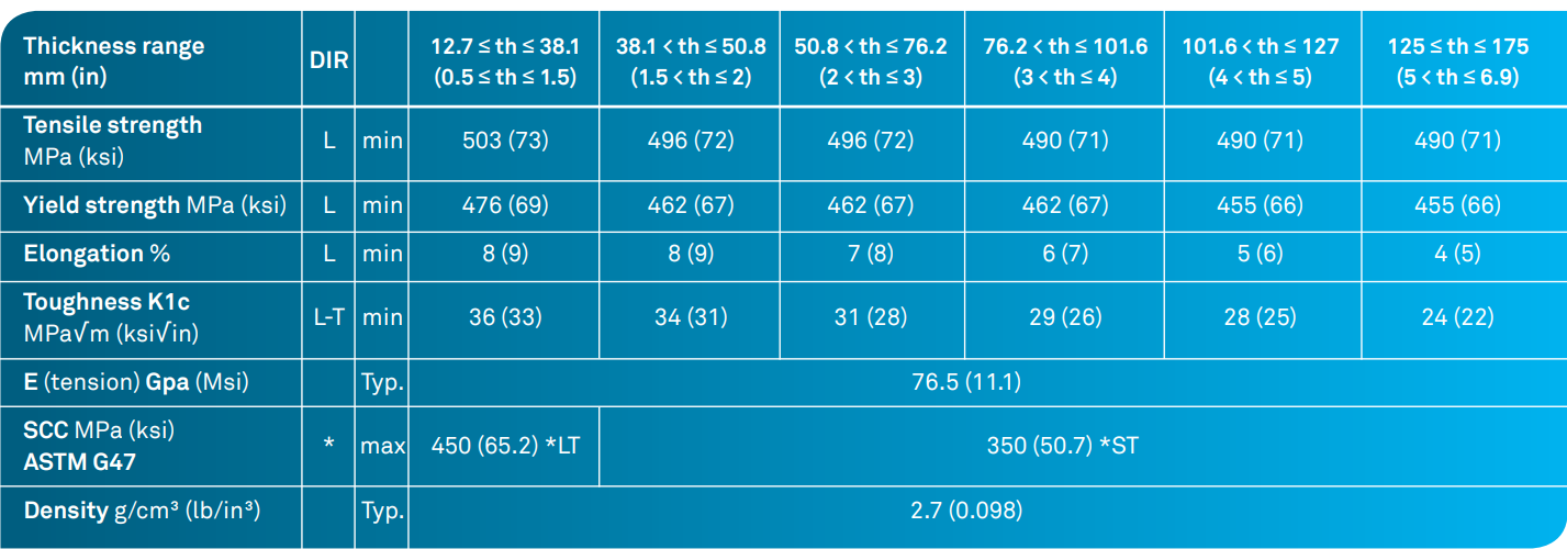
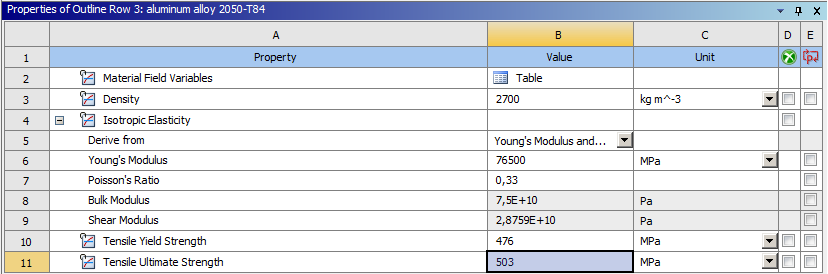
The coupler is machined in 2050-T84 aluminum alloy. This alloy has the following properties:
¶ Load case
Being part of the main structure of the rocket, the most important load the couplers will have to support is the tension due to the deployment of the parachute which corresponds to a 30g acceleration. This gives us the following force:
As a coupler the part shall also withstand an bending moment of 7500 Nm and a compressive force of 15000 N.
- 2024_C_SE_ST_COUPLER_REQ_07 Mechanical axial loads
The CPLRs shall resist axial parachute deployment loads of [30]g with an additional FoS of [2]. - 2024_C_SE_ST_COUPLER_REQ_19 Coupler load case - traction
The Coupler shall withstand [132000]N of tensile loads - 2024_C_SE_ST_COUPLER_REQ_21 Coupler load case - bending
The Coupler shall withstand [7500]Nm of bending moment. - 2024_C_SE_ST_COUPLER_REQ_20 Coupler load case - compression
The Coupler shall withstand [15000]N of compression loads.
¶ Finite Element Analysis
¶ Software
This FEA analysis was performed with the ANSYS Mechanical software for a static structural analysis. The CAD of the different parts was designed using Solidworks.
¶ Type of simulation
The simulation performed was a static structural analysis to estimate the Von mises constraints for the load cases of 132 kN in traction, 15 kN in compression and 7500 Nm in bending.
¶ Inputs
The set of units used for this simulation is: mm, t, N, s, mA, mV.
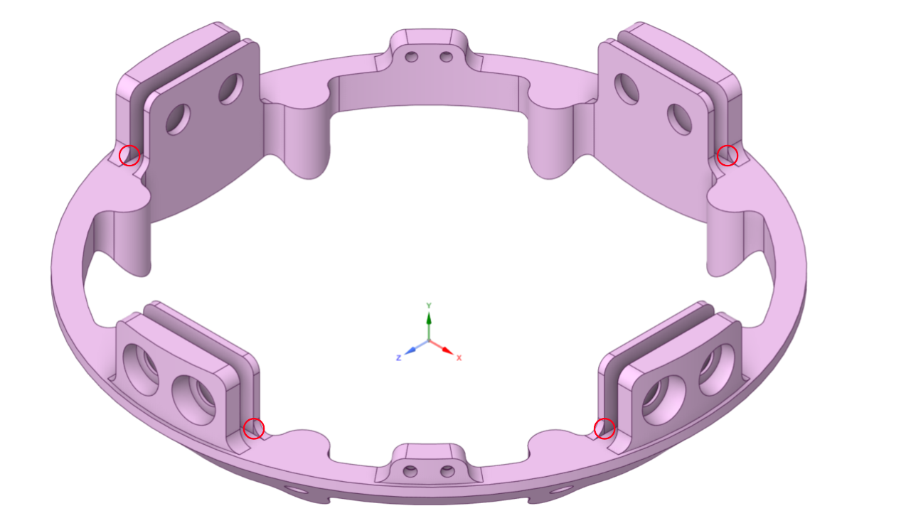
The geometry has been modified using spaceclaim. We added edges in order to define more precisely the contact area between the inside of the ears and the CFRP rods, as shown on the following image:
The couplers are manufactured in 2050-T84 aluminum alloy. We used only the isotropic material properties, where we know the Young's modulus, the poisson ratio, the density, the Yield strength and the tensile strength. The following image shows the material properties implemented in the software.
Time was not taken into account for this simulation.
The following boundary contitions were applied:
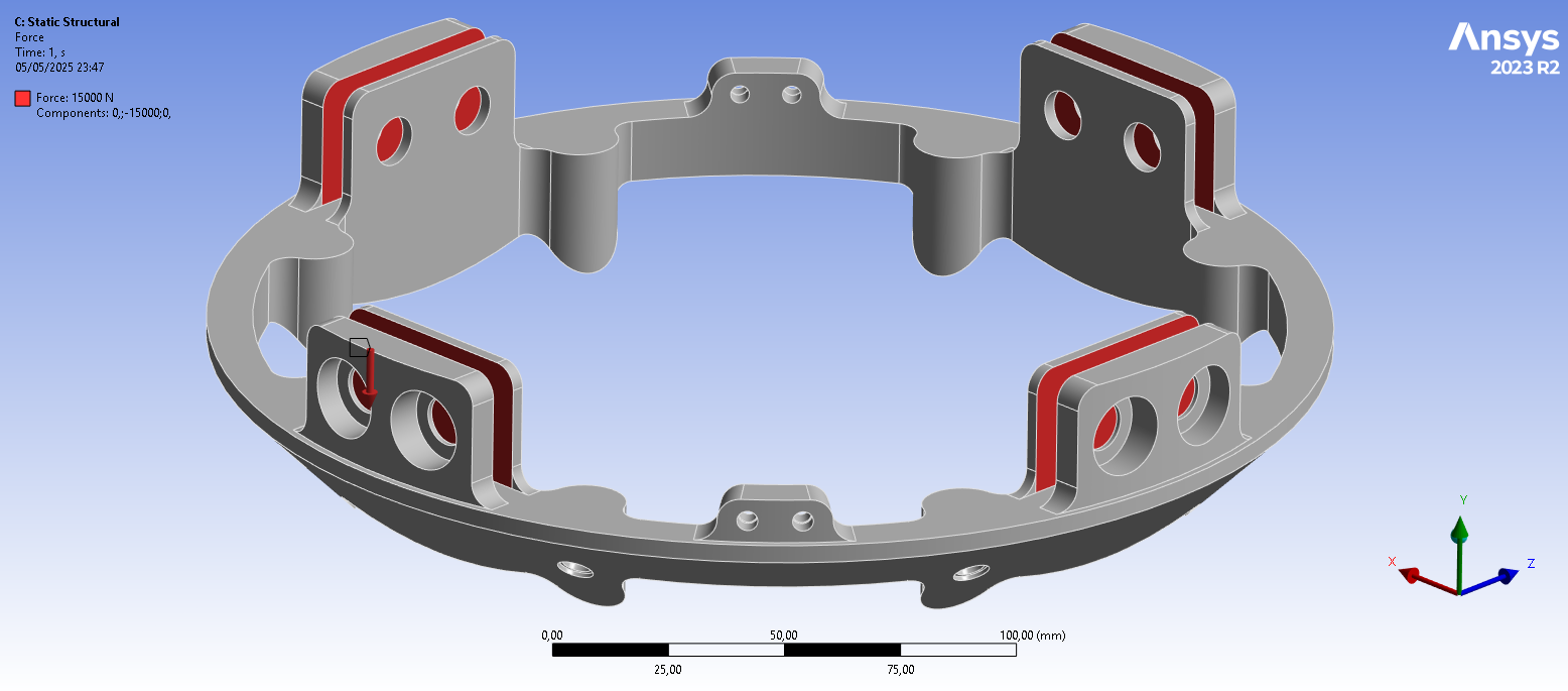
¶ Force load cases
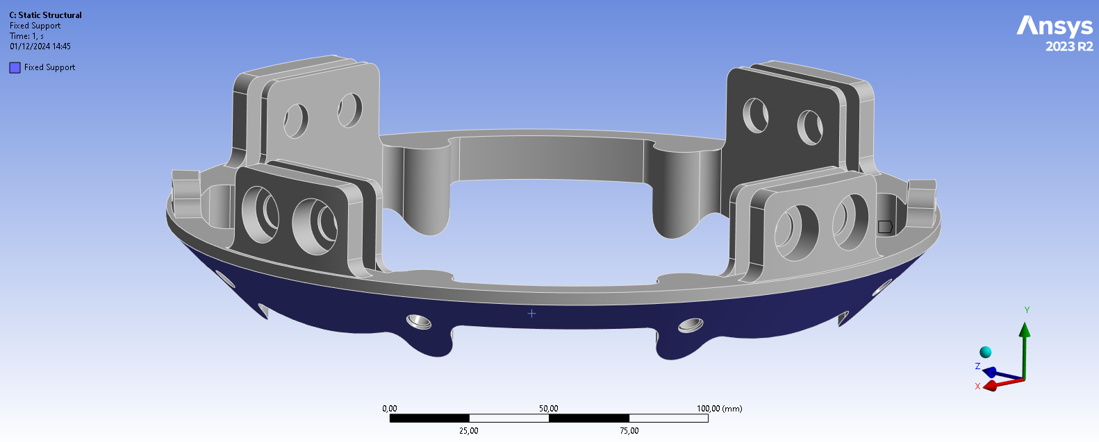
- Clamped surfaces: The conical surface of the coupler has been blocked in all directions and rotations.
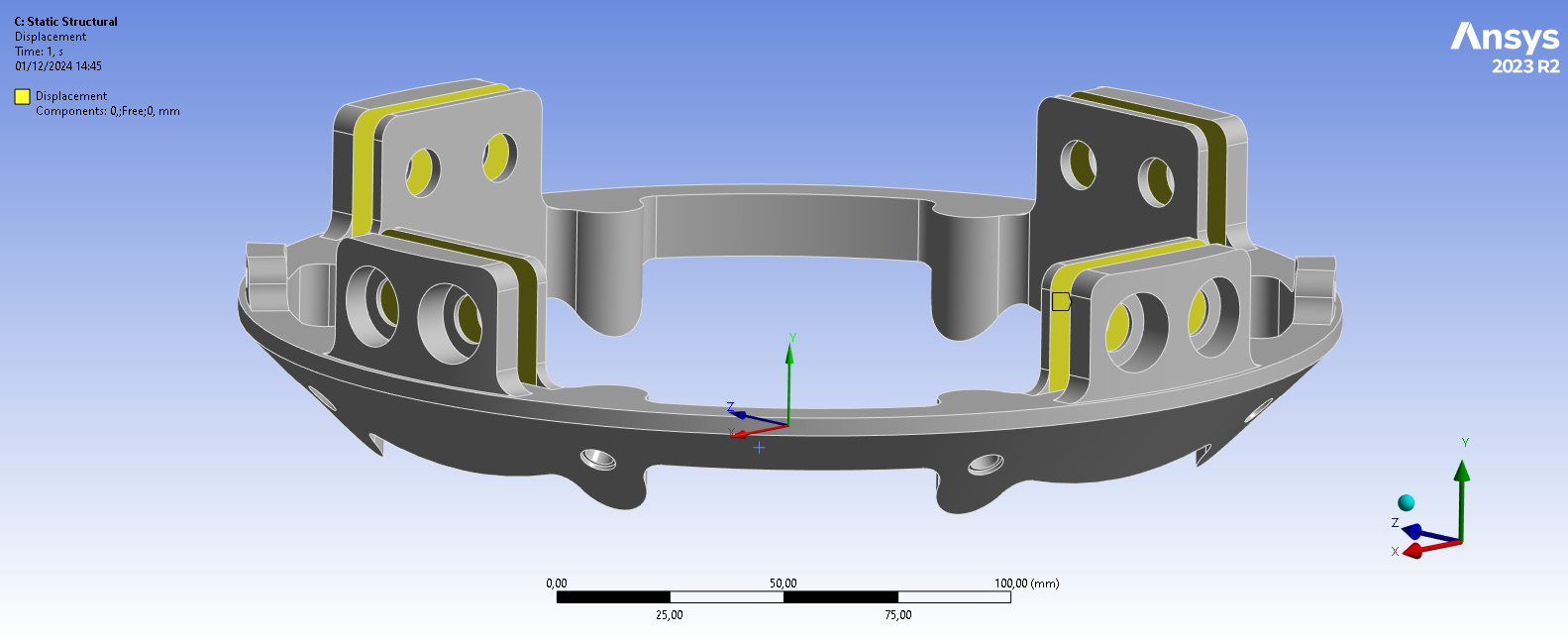
- The Inside of the ears were made to have a displacement of 0 in x and z, only allowed to move in the y direction. This is to simulate the carbon fiber rods in the ears.
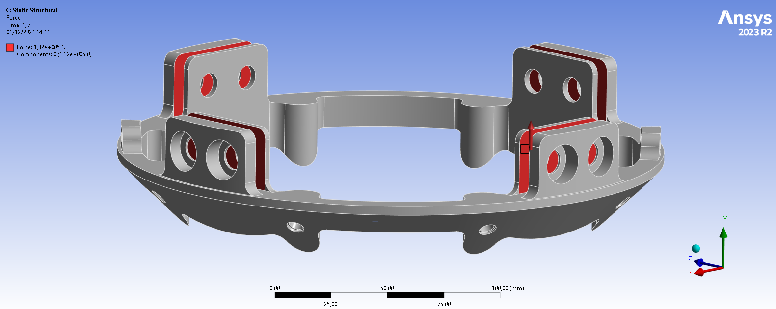
- An upwards force of 132000 N has been applied on the inner surfaces of the 4 ears, corresponding to 16500 N per face.
- For the compression case, an downwards force of 15000 [N] has been applied on the inner surfaces of the 4 ears, corresponding to 1875 [N] per face.
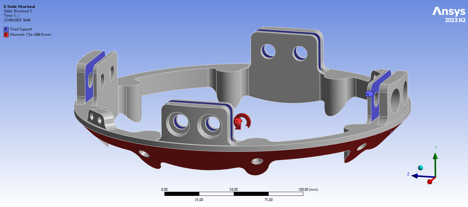
¶ Moment load case
The following boundary contitions were applied:
- Clamped surfaces: The surfaces inside of the ears of the coupler has been blocked in all directions and rotations.
- A moment of 7500000 Nmm around the x-axis has been applied on the conical surface of the coupler.
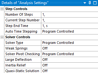
Analysis settings were left program controlled which gives the following settings:
¶ Mesh
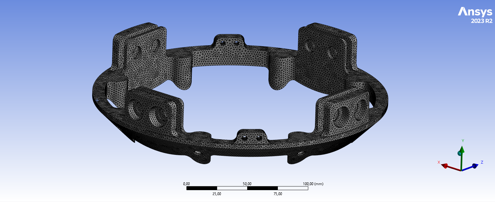
We choose to use the 3D solid elements to realize our analysis. The mesh is constituted of tetrahedral mesh of quadratic element order (Tet10).
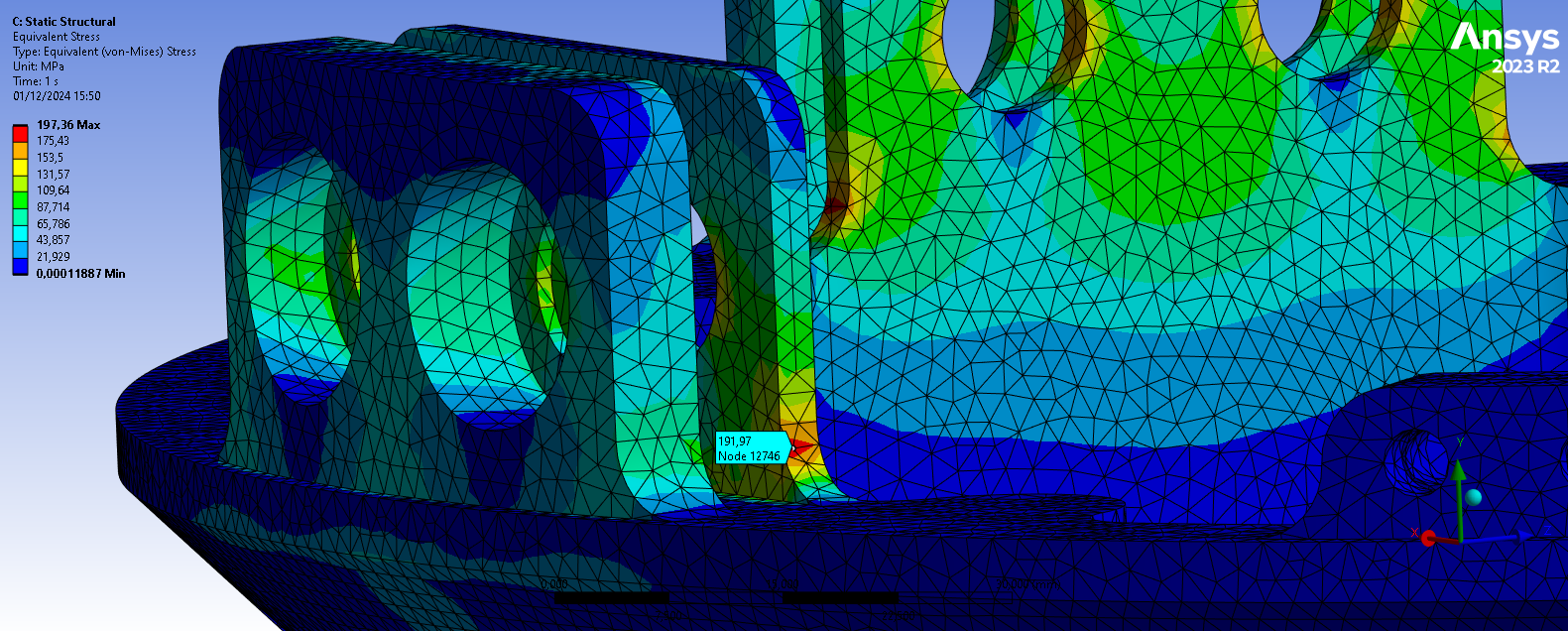
To verify mesh convergence, we probed the stress under the tension load case at the same node on a curve at the bottom of an ear as it is the area most prone to high stress:
The 'size' quantity refers to the sizing setting applied on the geometry.
| Size (mm) | 2 | 1 |
|---|---|---|
| Stress (MPa) | 191.97 | 191.49 |
| Deltas (%) | / | -0.25 |
We use the mesh with an element sizing of 2 mm as it is sufficiently refined (less than 2% difference with the finest mesh).
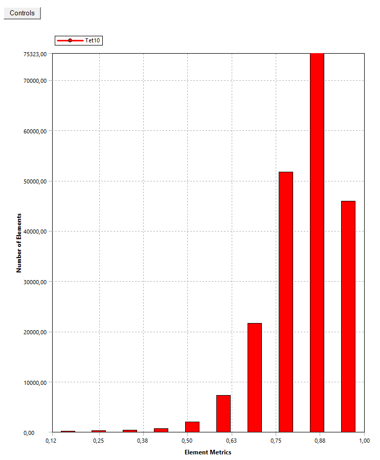
The final mesh is the one generated with an element sizing of 2 mm on the whole geometry. It contains 204677 elements and 317202 nodes. The average element quality is around 85%.
The following pictures illustrate the mesh as well as the element quality of the mesh.
¶ Outputs
¶ Tension load case
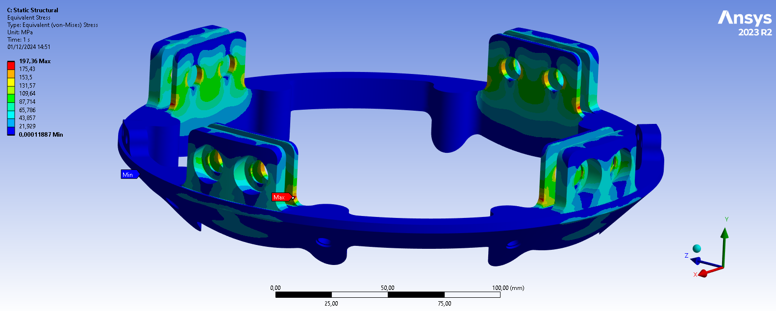
The maximal stress is found on the curve at the bottom of an ear. It has a value of 197.36 MPa. The couplers being manufactured in 2050-T84 aluminum alloy, its yield strength is of 476 MPa, which is not exceeded.
¶ Compression load case
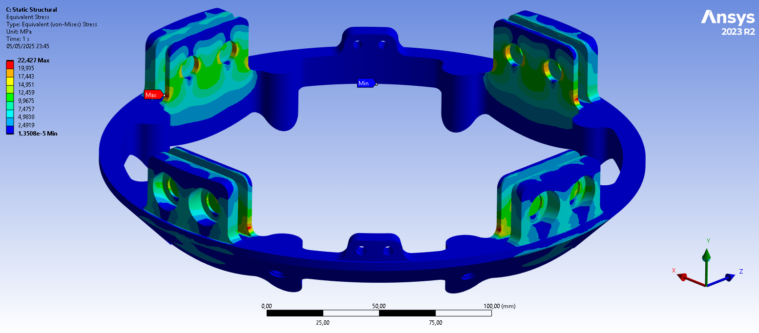
The maximal stress is found on the curve at the bottom of an ear. It has a value of 22.427 MPa. The couplers being manufactured in 2050-T84 aluminum alloy, its yield strength is of 476 MPa, which is not exceeded.
¶ Moment load case
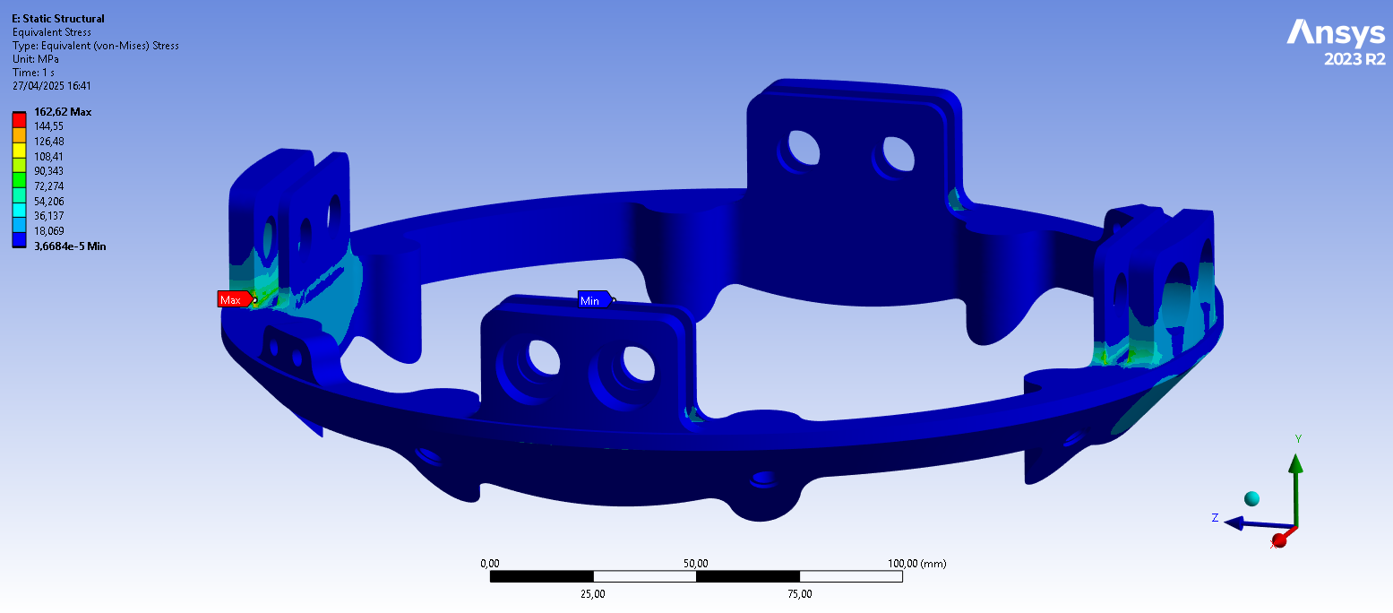
The maximal stress has a value of 162.62 MPa and is foud at the bottom of the ear under tension which is also under the yield strength of 476 MPa.
¶ Margin of Safety
The formula of the minimum Margin of Safety being the following:
We have:
¶ Tension load case
¶ Compression load case
¶ Moment load case
Which is greater than the required 0.25 in all cases.
¶ Conculsions
The main focus of the simulation was to determine if the yield strength of the material is exceded under the loads which the coupler is supposed to withstand i.e 132 kN in tension and 15000 N in compression, both in the direction of the CFRP rods, and a bending moment of 7500 Nm.
¶ Force load case
The simulation results indicate that under such a load, the maximal von mises equivalent stess within the part has a value of 197.36 MPa which corresponds to a margin of safety of 1.41 which is over the 0.25 required. Therefore the following requirement is verified.
- 2024_C_SE_ST_COUPLER_REQ_19 Coupler load case - traction
The Coupler shall withstand [132000]N of tensile loads
¶ Compression load case
The simulation results indicate that under such a load, the maximal von mises equivalent stess within the part has a value of 22.427 MPa which corresponds to a margin of safety of 20.22 which is well over the 0.25 required. Therefore the following requirement is verified.
- 2024_C_SE_ST_COUPLER_REQ_20 Coupler load case - compression
The Coupler shall withstand [15000]N of compression loads.
¶ Moment load case
The results indicate that under the load case of 7500 Nm, the maximal von mises equivalent stess within the part has a value of 162.62 MPa which corresponds to a margin of safety of 1.93 which is well over the 0.25 required. Therefore, we can conclude that the following requirement is verified.
- 2024_C_SE_ST_COUPLER_REQ_21 Coupler load case - bending
The Coupler shall withstand [7500]Nm of bending moment.
Overall, all requirements are verified so we can validate the design for FH 9.