¶ 216301_Fins
¶ Geometry
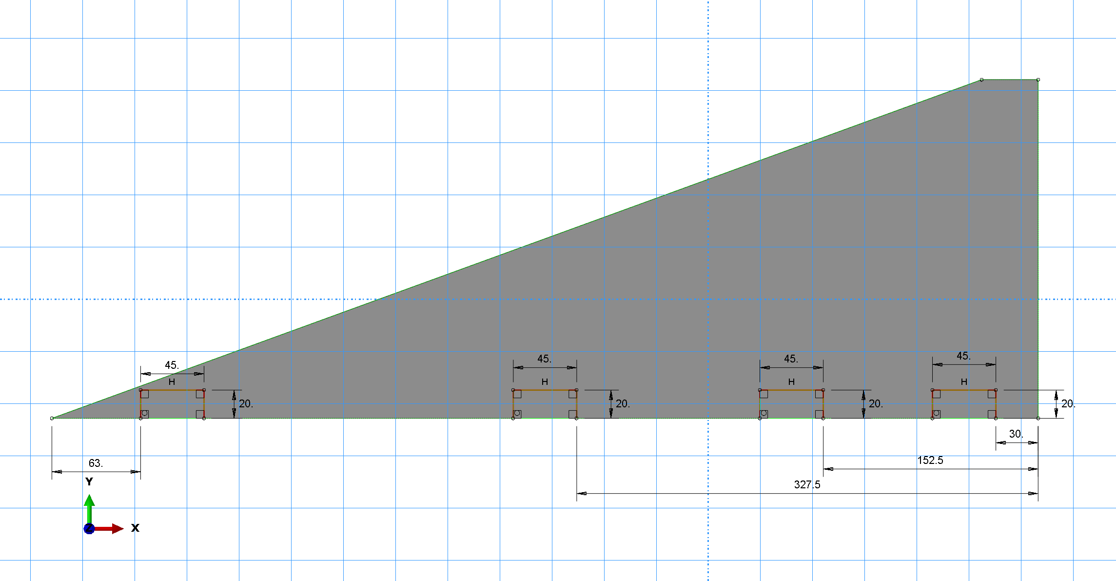
- Root chord = [mm]
- Tip chord = [mm]
- Heigth = [mm]
- Sweep length = [mm]
- Sweep angle = [°]
- Targeted thickness = [mm]
¶ Function
Rocket fins play a vital role in the stability and control of rockets during flight. These aerodynamic surfaces are typically located at the tail end of the rocket and are designed to generate forces that counteract any unwanted motion, such as roll, pitch, or yaw. Fins provide stability by creating aerodynamic forces that help maintain the rocket's desired trajectory and prevent it from veering off course.
¶ Material
Prepregs
Epoxy based CFRP from Hexcel (HexPly®)
| Denomination | Prepreg | Type | Thickness [mm] |
|---|---|---|---|
| a | EH25/34%/UD136/HTA-12K | UD | 0.14 |
| b | W3T-282-42'-F593-14 | Plain | 0.24 |
Core
- Material: ECA C2-3.2-29 (aramid honeycomb)
- Denomination: C
- [kg.m-3]
- Thickness = [mm]
Lay-up: [0b,[0a,45b,0a]S,0b,C]SO
Thickness = [mm]
¶ Load case
- The fins shall withstand a normal force of up to [N].
¶ Finite Element Analysis
¶ Software
Altair EsaComp: material properties
ABAQUS CAE: Meshing program
ABAQUS Standard: FEA
¶ Type of simulation
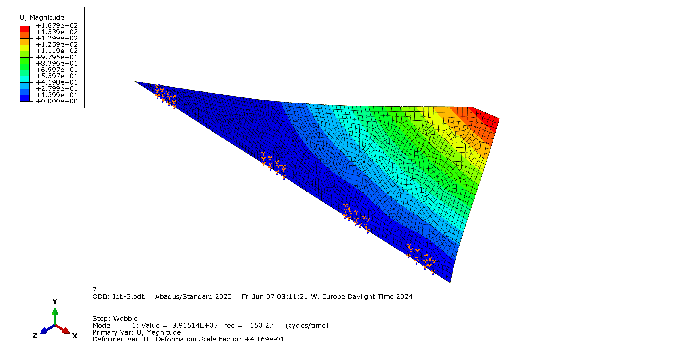
- Modal
- Static structural
¶ Goal of the simulation
This analysis aims to validate the structural integrity as well as to find the natural frequencies of the final lay-up design proposed.
¶ Inputs
mmNS: mm-ton-N-Nmm-MPa-mm^4-mJ
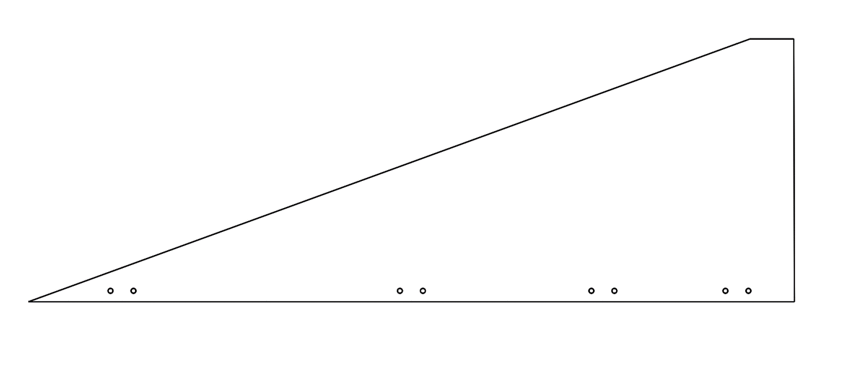
The leading and trailing edges do not have sharp angles. The geometry is a simple 2D figure.
REMOVE THIS TEXT
Density
|---|---|
| Material | Density |
| a | 1.482E-09 |
| b | 1.4375E-09 |
| C | 2.9E-11 |
Elastic
| Lamina||||||||||
| Material | E1 | E2 | Nu12 | G12 | G13 | G23 |
|---|---|---|---|---|---|---|
| a | 137000 | 10500 | 0.3 | 5200 | 5200 | 3477 |
| b | 49000 | 49000 | 0.05 | 5000 | 4500 | 4500 |
| C | 1E-06 | 1E-06 | 0.05 | 1E-06 | 27 | 16 |
| Fail stress ||||||||
| Material | Ten Stress Fiber Dir | Com Stress Fiber Dir | Ten Stress Transv Dir | Com Stress Transv Dir | Shear Strength | Cross-Prod Term Coeff | Stress Limit
|---|---|---|---|---|---|---|
| a | 2000 | -1350 | 70 | -240 | 105 | -0.5 | 0 |
| b | 550 | -485 | 550 | -485 | 100 | -0.5 | 0 |
- Steady-state
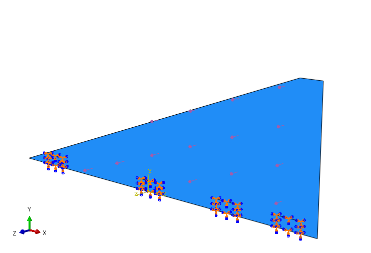
Partially clamped at the root chord
- Constraint: Encastre
- Target: Clamps' positions
- Constrained DoF: U1=U2=U3=0 & UR1=UR2=UR3=0
Normal load
- Load: Surface traction
- Magnitude: Magnitude = [MPa]
- Target: Surface
¶ Mesh
- Element library: Standard
- Element family: Shell
- Element shape: Quad
- Geometric order: Quadratic
Natural frequencies are chosen as convergence criteria
|---|---|---|---|
|Size [mm] | | | |
Freq. 1 [Hz] ||||
Deltas [%]|/|||
Freq. 2 [Hz] ||||
Deltas [%]|/|||
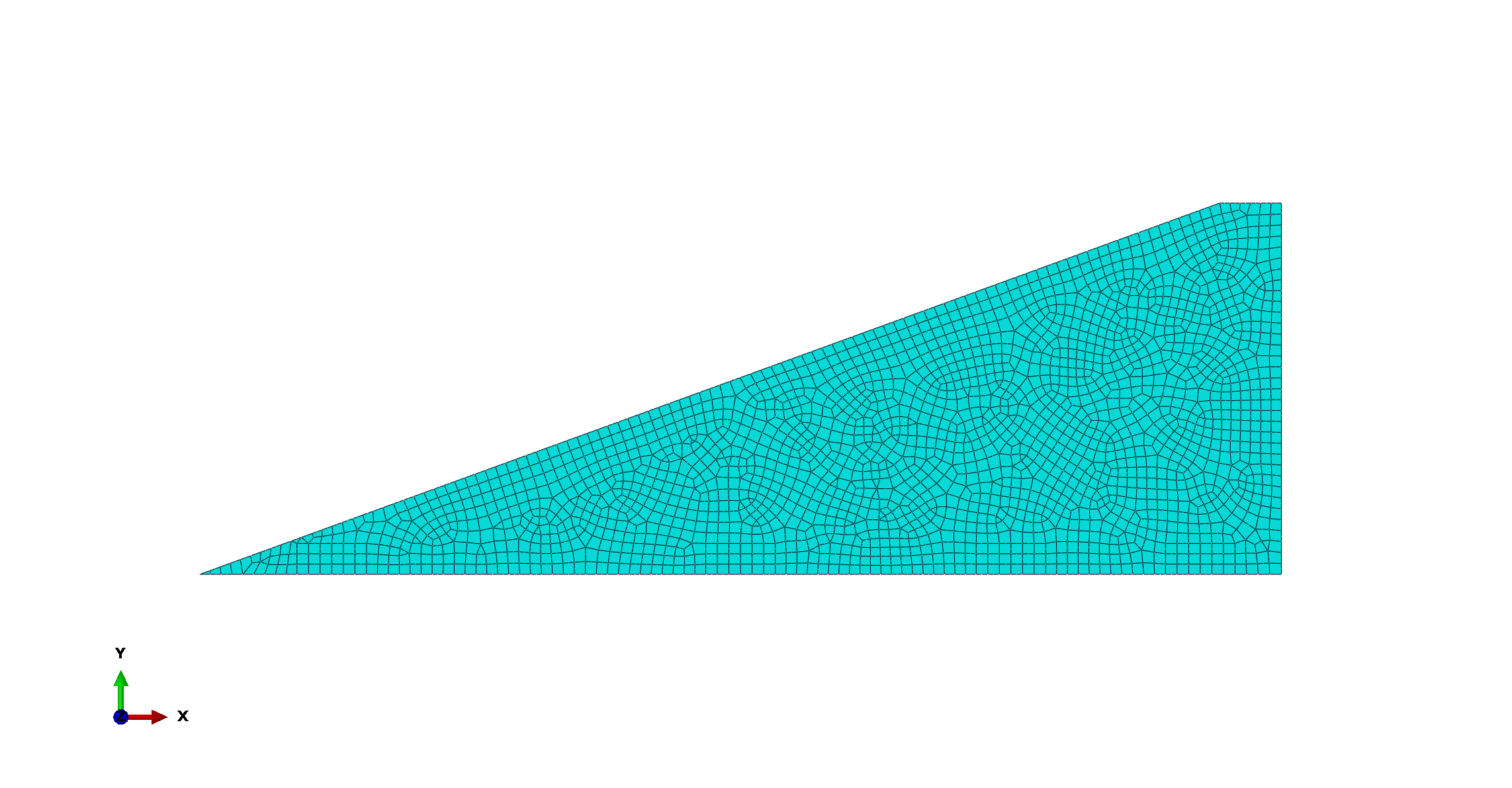
Final mesh size: [mm]
¶ Outputs
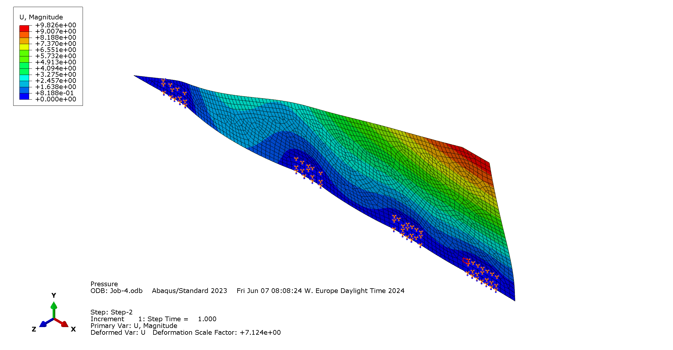
There is no maximum displacement requirement but overall [mm].
 |
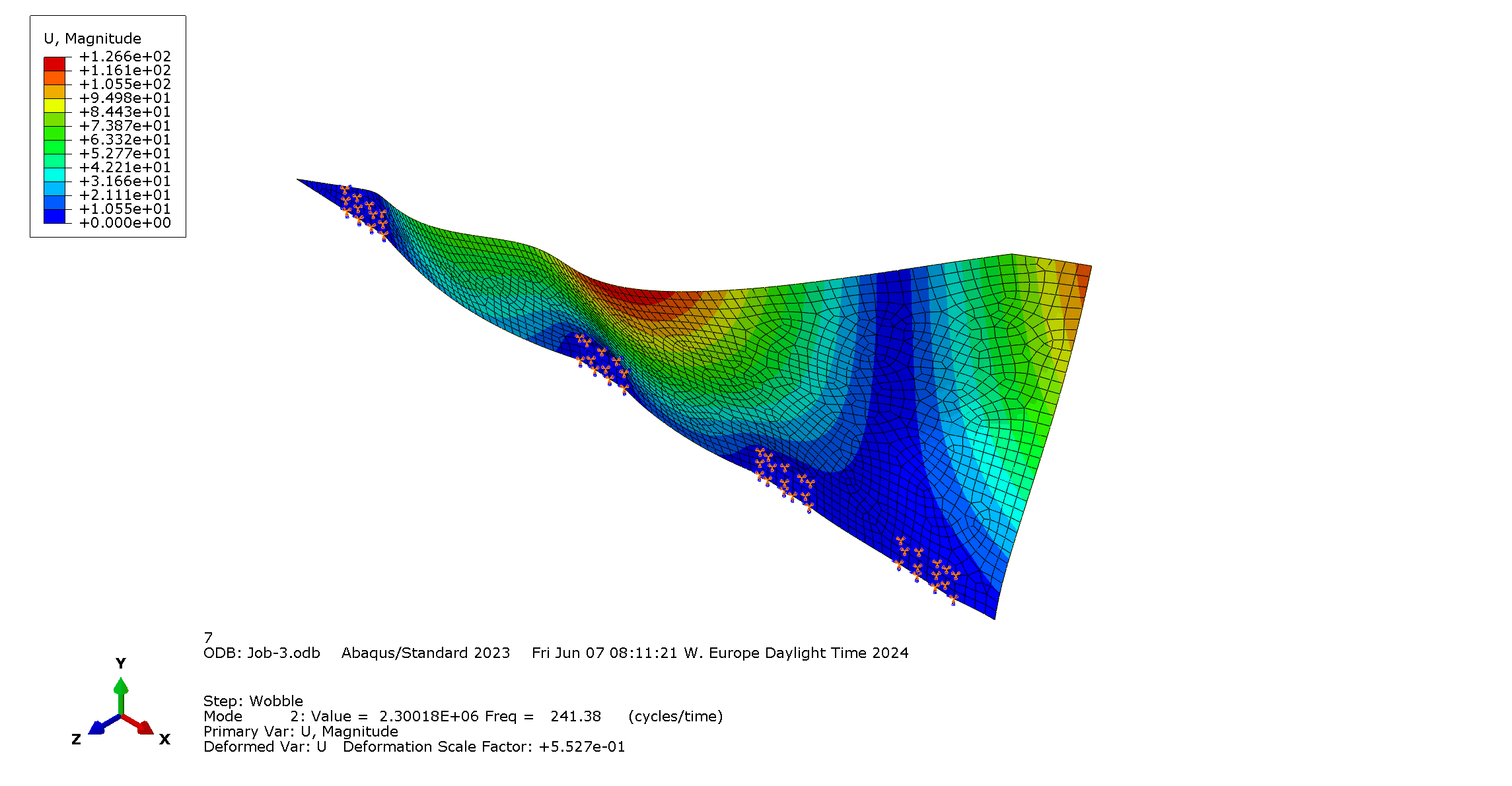 |
|---|---|
| 1st mode: Flexural mode with eigenfrequency [Hz] | 2nd mode: Torsional mode with eigenfrequency [Hz] |
The part resists load if TSAIW
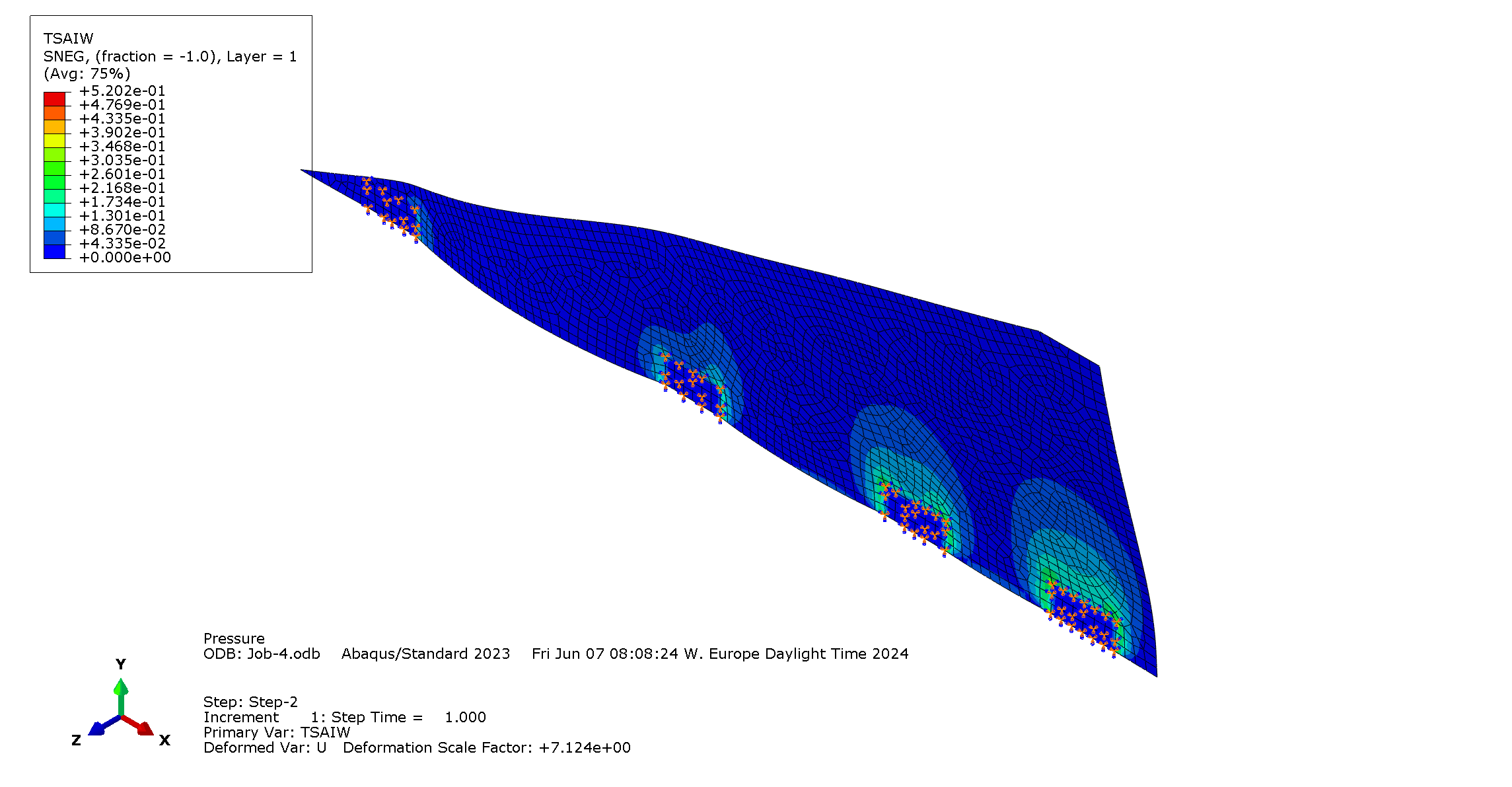
everywhere.
Outputs right at the clamps not relevant. It can be expected from the boundary condition that there will be a load concentration there. Therefore, the maximum value considered is taken around the clamps: .
|---|---|---|---|---|
| |Value (extremum)| Minimal | Location |
| Displacement [mm] | | / | Tip chord |
| Tsai-Wu | 0.2168 | 3.61 | Around the clamps |
| Freq. 1 [Hz] | | / | / |
| Freq. 2 [Hz] | | / | / |
¶ Interpretation
¶ Simulation validity
This analysis insurance on the strength of the chosen design with the provided load case. It also gives some indications on the displacement and vibratory behaviour of the design with the current clamping system. However, assembly simulation is necessary to validate the latter.
¶ Conculsions
In brief, this FEA provides some guidelines on the structural integrity of the current fin design. Additional vibratory tests can be performed to validate the simulations.