¶ Introduction
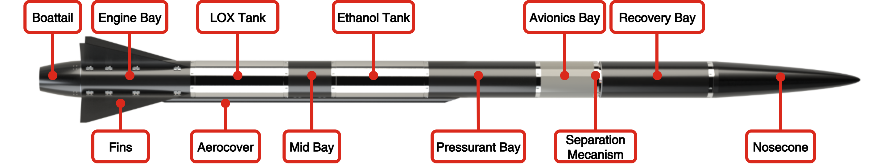
This Design Definition File (DDF) aims to give an overview of what the Structure sub-system has achieved for the launch vehicle Firehorn I.
The Structure sub-system has two main responsibilities:
- Guaranteeing the structural integrity of Firehorn I
- Ensuring that every sub-system can be integrated in Firehorn I
To do so, the sub-system designed, manufactured and tested the mechanical parts of the bays defined by the systems engineers.
The design phase follows a funnel model. Each bay is associated with an assembly, which is composed of multiple subassemblies, which are composed of multiple parts.
Next comes the manufacturing phase, coupled with the testing phase. There are two types of parts: aluminum and fiber-reinforced composite (FRP). The first ones are machined in professional workshops under the team's close supervision. The second ones are SRAD. Critical assemblies undergo iterative prototyping, followed by qualification testing to finalize them.
This document is organised as followed:
- Main sub-system requirements
- Interfaces with other sub-systems
- Launch vehicle structure specs
- Architecture
- Assemblies
¶ Applicable and Reference Documents
¶ Requirements
- 2024_C_SE_REQ_DB Requirements Database
¶ Interfaces
¶ Propulsion
The interfaces with Propuslsion sub-systen span from the pressurant bay till the engine-bay. Basically, the internal structure is designed to facilitate the integration and access to the plumbing system. The pressurant bay hosts the COPV which contains the pressurant gas. The mid bay serves as transition bay between the two tanks. Lastly the engine bay contains the engine and transmits the thrust through the whole vehicle.
The Structure sub-system is responsible for the design, manufacture and qualification of the ethanol and liquid oxygen tanks.
¶ Avionics
The Structure sub-system is responsible for the design and manufacture of the avionics integration structure (AIS) which hosts the main PCBs and the battery pack.
The Avionics sub-systen manages the triggering of the separation mechanism. Indeed, the avionics send a current which triggers the mechanism when the appogee is detected.
¶ Recovery
The interface with the Recovery sub-system is mainly physical. In fact, the Structure sub-system is responsable for the design and manufacture of the parts which host the parachute. Moreover, it is its duty to ensure that the vehicle can withstand the heavy loads of the parachute opening.
¶ Payload
The Structure sub-system is responsible for the design and manufacture of the payload bay which hosts the payload.
Moreover, it guides the Payload sub-system for the integration of the embedded cameras.
¶ Ground Segment
The Structure sub-system is responsible for the design and manufacture of the hold-down system which allows the vehicle to reach its nominal thrust before lifting-off.
Additionally, it defines where in the vehicle the ground segment equipments are plugged during launch preparation.
¶ Overview
¶ Architecture
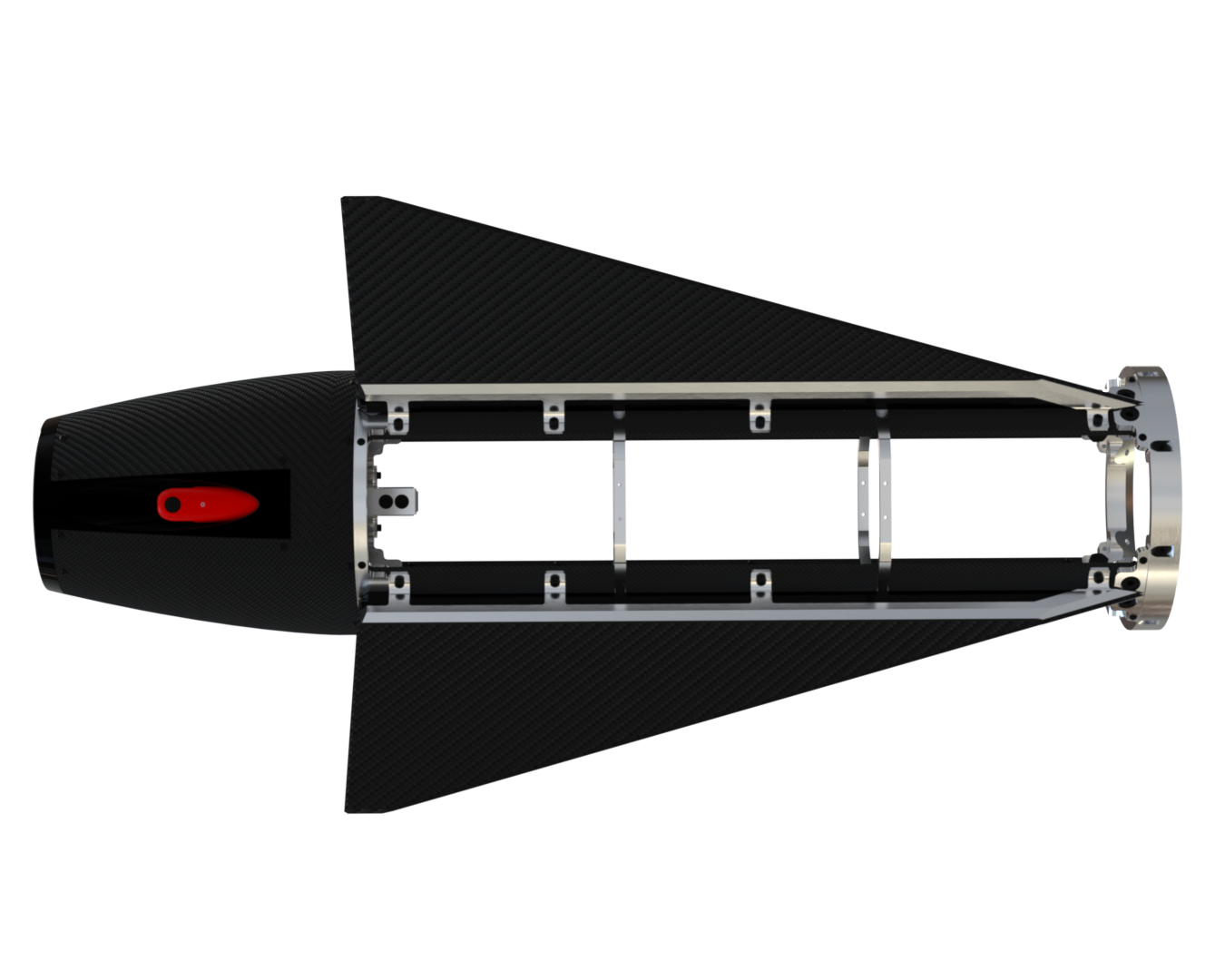
¶ Internal Structure
The internal structure aims to ensure the structural integrity of the rocket. For this, it must both keep all the subsystems together and withstand all the loads applied to it. As the design of the internal structure of the previous rocket Nordend proved to be very resilient and practical, it was decided from the start that a similar design would be used for Firehorn.
We therefore kept the general idea of the structure and adapted it to the new loads and requirements.
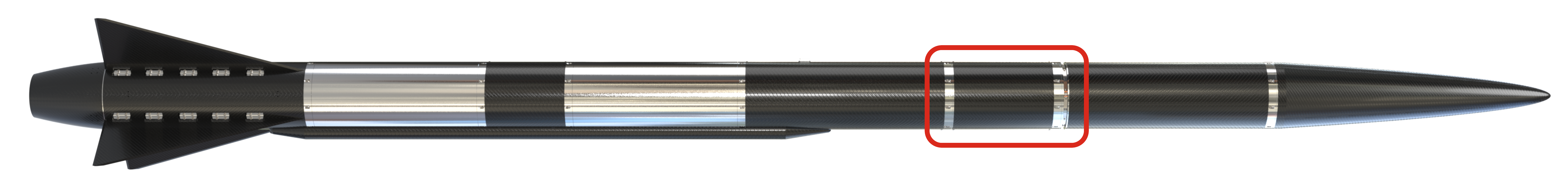
The avionics bay contains the rocket's avionics. It is located between the pressurization bay and the recovery bay. This bay is connected to the parachute, and interfaces with the separation mechanism that releases the parachute after apogee.
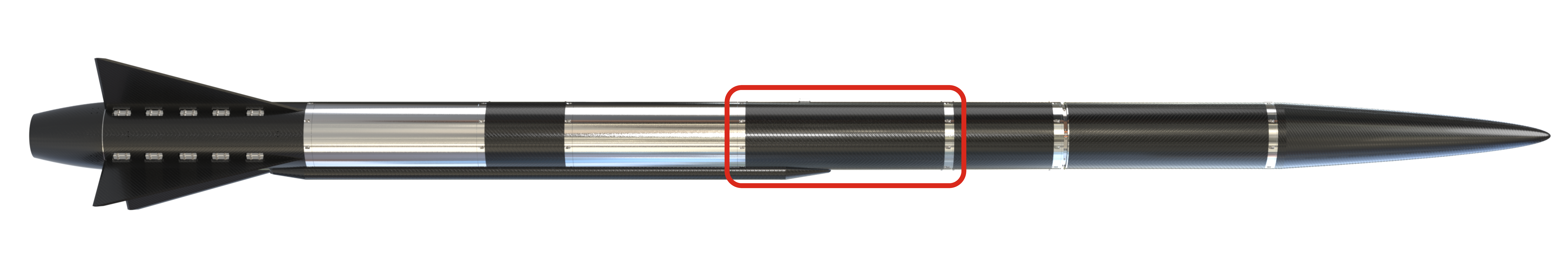
The pressurant bay contains the pressurization system for the two tanks. This consists of plumbing and a COPV containing the pressurized gas. It is located between the ethanol tank and the avionics bay.
The mid bay contains the plumbing needed to pressurize the liquid oxygen tank and deliver ethanol to the engine. It is located between the Lox tank and the ethanol tank.
The engine bay contains the plumbing leading to the engine and the engine itself. It is located below the LOX tank.
|:--- :---
:---
| |
| |
|
The RRB consists of four parts: the rail button, which interfaces with the launch rail and withstands system forces; the chassis, which connects the button to the rocket and houses its retraction; the rods, which hold the assembly and enable spring-driven retraction after launch; and the washer, which prevents airframe contact with the rail while reducing friction.
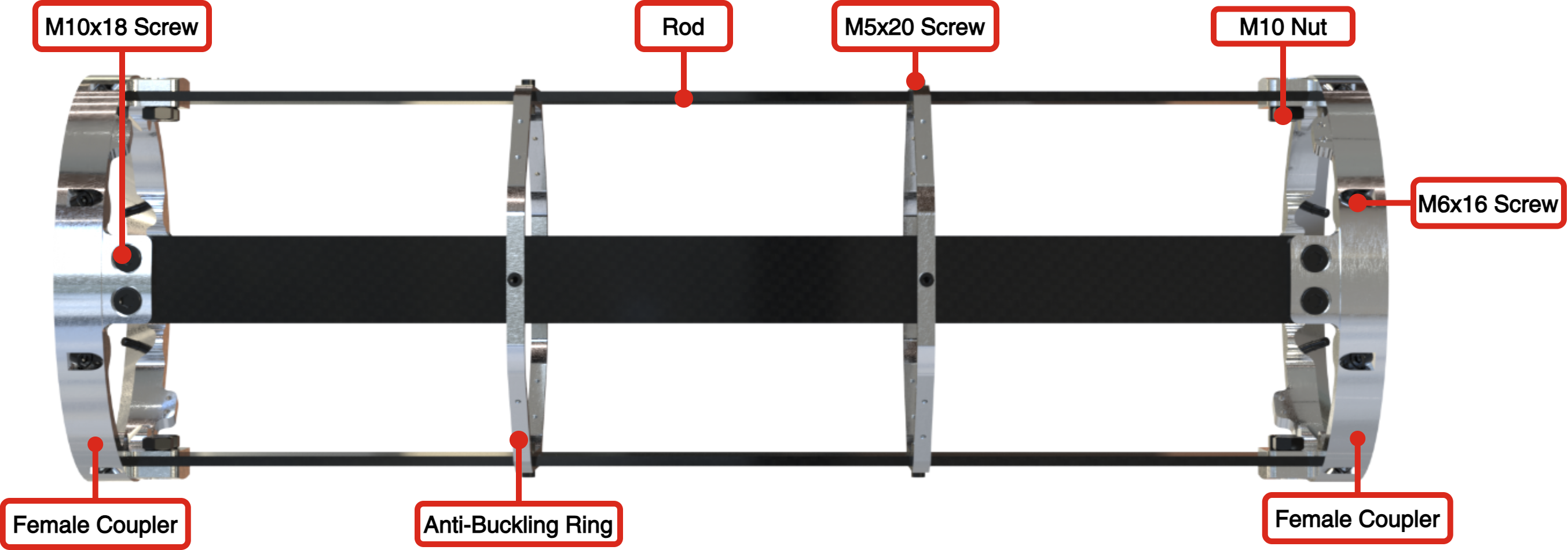
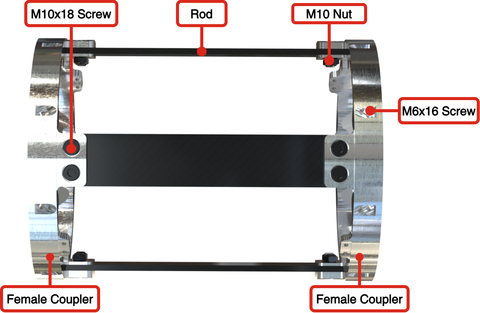
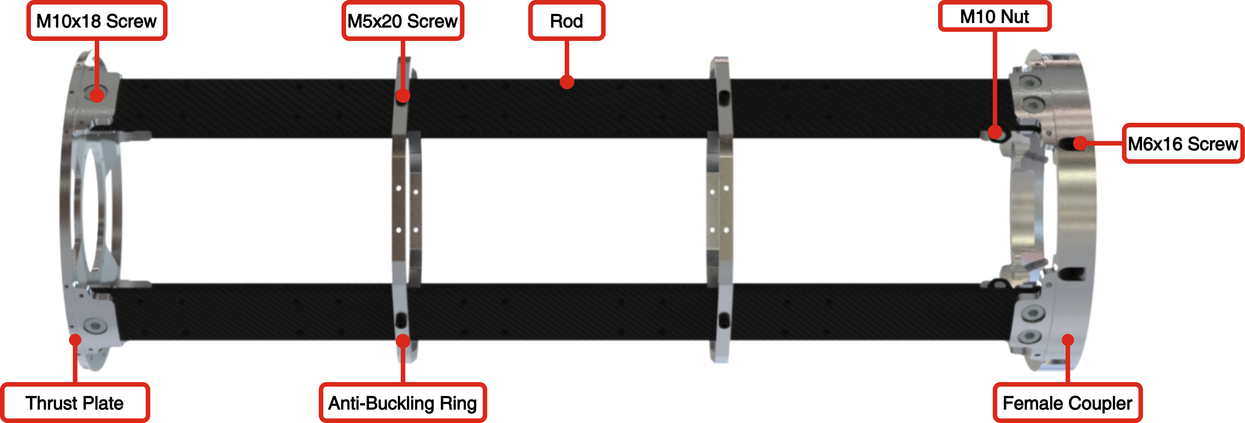
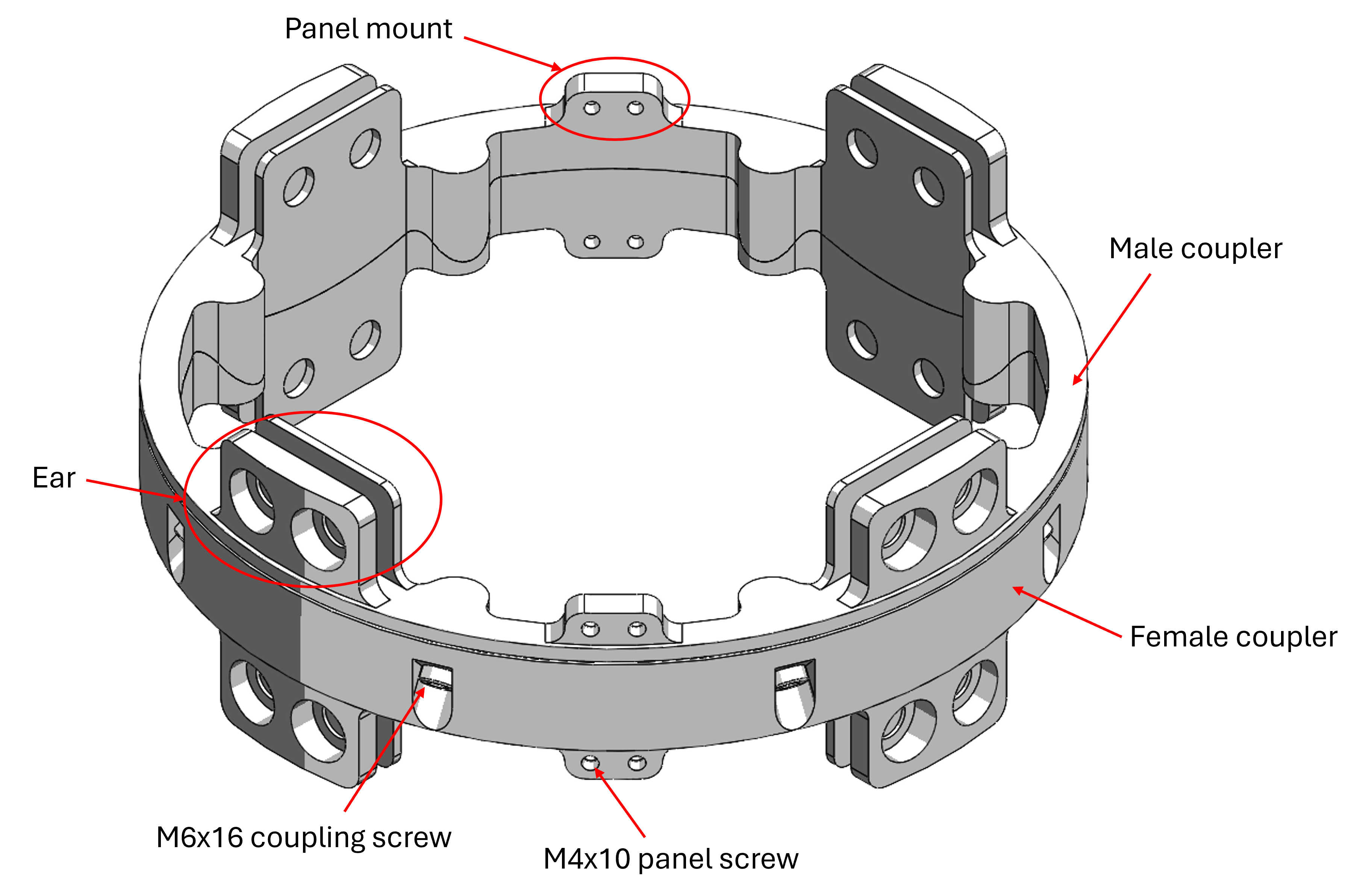
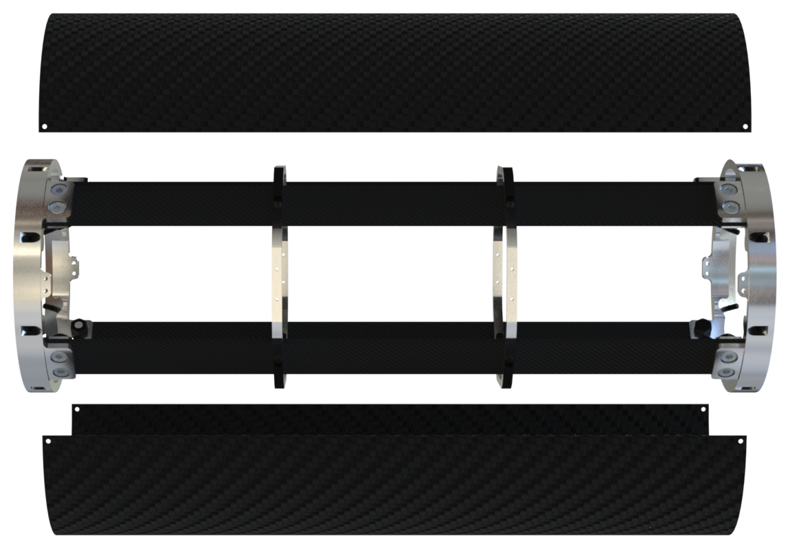
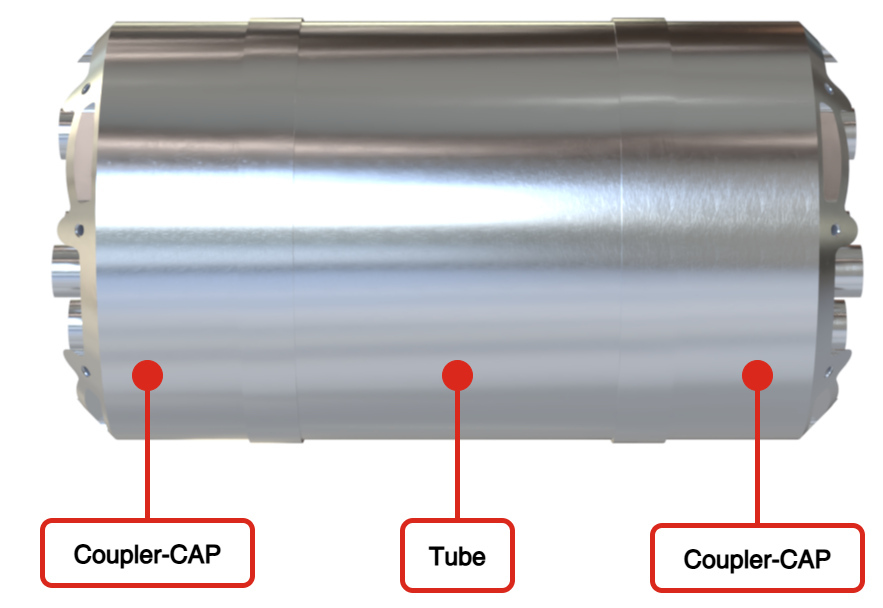
¶ Couplers
The main function of couplers is to assemble the various modules of the Firehorn rocket. For this purpose, it should be compliant with the structural rods architecture. In addition, it has to accommodate panel mounts to fix the airframe panels. In parallel to achieving these functions, the goal was to design couplers that can be easily adapted to future larger rockets, by being scalable and by providing flexibility for operations and interfaces (i.e. can also be used with previous rockets architectures such as couplers glued in CFRP tubes). The reference coupling system of Firehorn rocket is presented below: it is used when two modules with rods architecture and panels must be assembled.
|:---:---
| |
| |
|
¶ Airframe
The airframe is removable and mostly non-structural as the loads are taken by the internal struc-
ture. Only the recovery bay is structural. The airframe is of fiber-reinforced composite, either
CFRP or GFRP. CFRP is generally preferred except when there is a need for radio frequency
transparency.
.png)
¶ Assemblies
¶ Nosecone-Bay
¶ Description
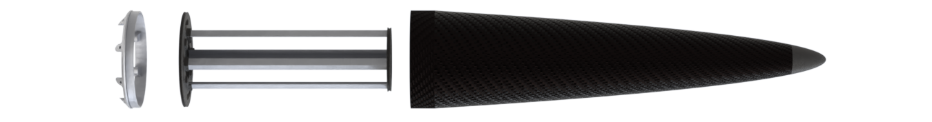
The Nosecone is a conical carbon fiber composite part, manufactured using vacuum prepreg procedure on a 3D-printed thermoplastic mold. Its front end incorporates a modular, removable tip system, optimize for mass efficiency and easy interchangeability in case of damage.
¶ Main Specifications
| Specification | Value | Unit |
|---|---|---|
| Dimensions | 1003 | [mm] |
| Mass | 450 | [g] |
| Design Load (tensile) | 4800 | [N] |
| Materials | CFRP / Al-2050 / PET-CF | |
| Manufacturing | Prepregs / 5-axis CNC / 3D-printing |
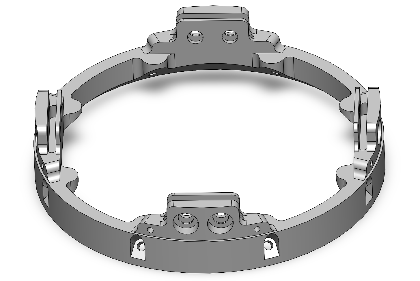
¶ Recovery-Bay
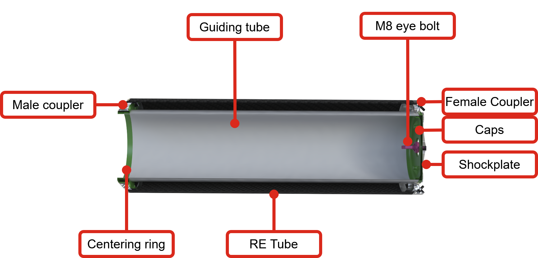
¶ Description
The recovery bay is composed of a structural carbon fiber composite tube, with a glued female coupler at the top and a glued male coupler at the bottom. There is a guiding tube inside, housing the recovery module, including the pilot parachute, the main parachute in its deployment bag, the shock cords, and the trigger boards used to unreef the main parachute.
The glued male coupler at the bottom is assembled with the separation mechanism, allowing the parachute to deploy at apogee.
At the top, a shock plate with an eyebolt rests against the female coupler, while a 3D-printed cap separates the guiding tube contents from the rest of the rocket and ensures smooth separation.
¶ Main Specifications
| Specification | Value | Unit |
|---|---|---|
| Dimensions | 715 | [mm] |
| Mass | 3258.5 | [g] |
| Design Load (tensile) | 4000 | [N] |
| Materials | CFRP / GFRP / Al-2050 / PET-CF | |
| Manufacturing | Prepregs / Infusion / 5-axis CNC / 3D-printing |
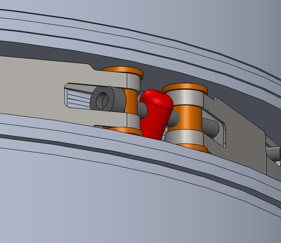
¶ Separation Mechanism
.png)
|:---:---
| |
| |
|
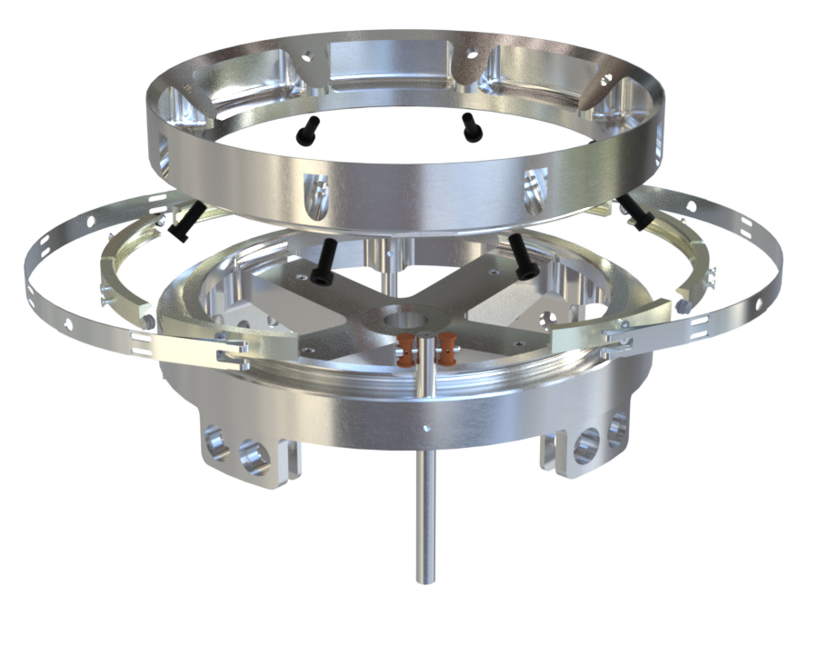
¶ Description
The separation sequence is triggered by the Avionics (AV) system immediately after detecting apogee. For Firehorn I, the first event corresponds to the separation of the LV into two parts at the Separation Mechanism (SepMec), located between the Recovery Bay (REB) and the Avionics Bay (AVB) as stated above.
This separation allows the deployment of the parachute, initiating the recovery sequence. It must occur promptly after apogee to ensure the parachute deploys before the descent speed becomes too high, which could cast excessive structural loads upon the LV.
The chosen design, similar to Nordend's, relies on clamping force to fasten and unify the LV. This design has demonstrated reliability in many previous ERT rockets and was selected early in the Firehorn project for its robustness.
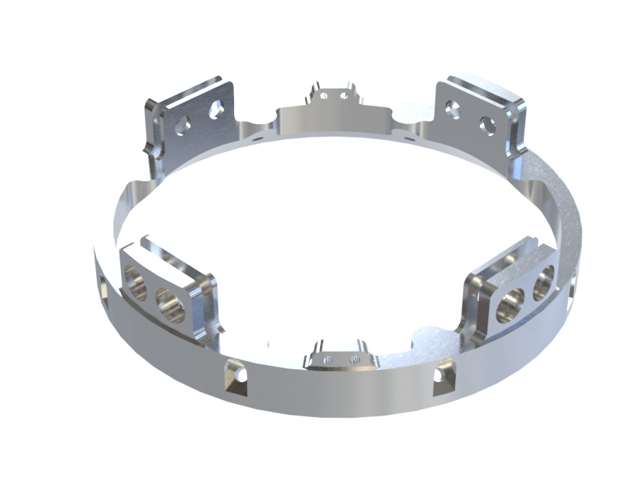
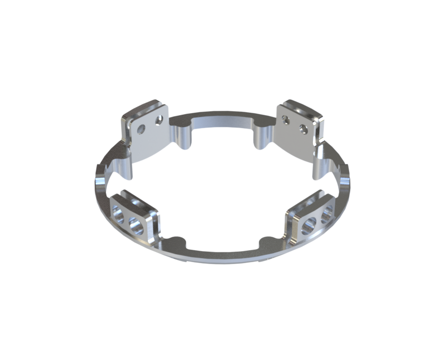
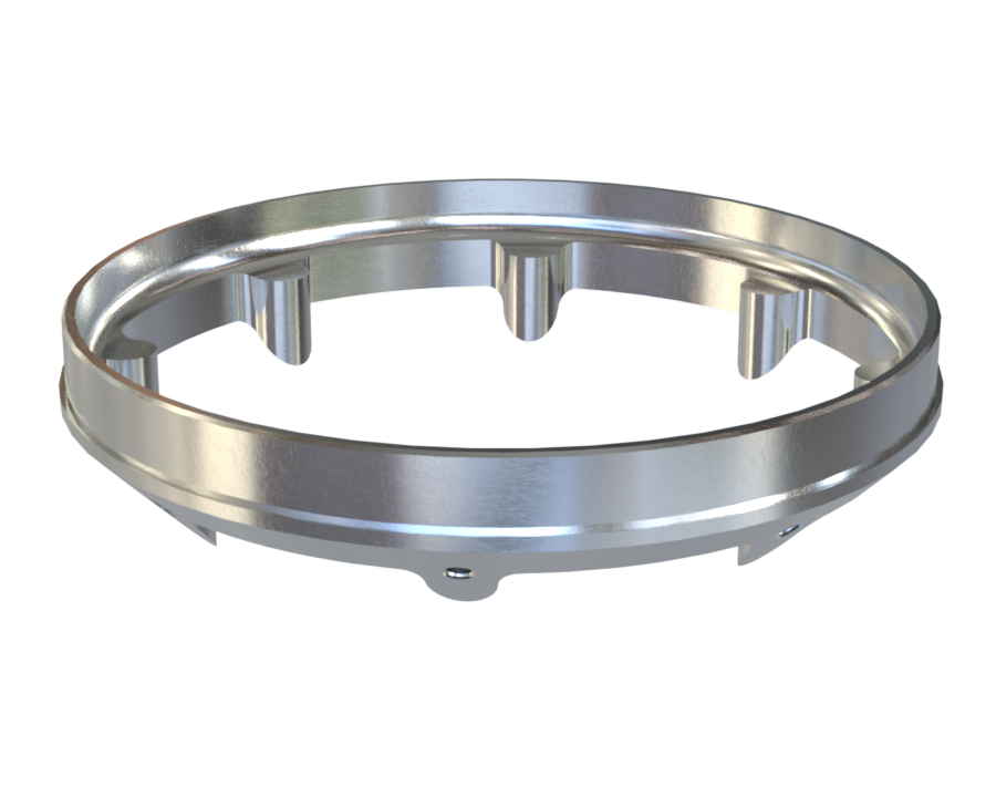
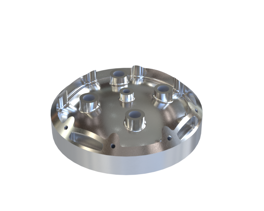
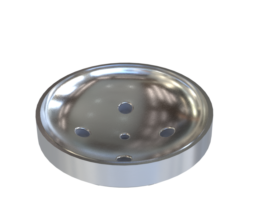
Therefore, the SepMech consists of four main components:
- Upper Ring: Upper ring half, REB-side, designed to be clamped to the Lower ring (opposite ring half).
- Lower Ring: Lower ring half, AVB-side, designed to be clamped to the Upper ring (opposite ring half).
- Clamp Band (CB): Spring steel band with metallic clamps attached to it. It is tightened via a screw to couple the Upper and Lower Rings, ensuring structural integrity under launch loads. During the first event, the CB is released and allows for stage separation.
- Pyrocutter: Pyrotechnic device that severs the M3 screws in the Clamp Band to release the latter and initiate LV stage separation. Two pyrocutters are positioned symmetrically on either side of the Clamp Band. They each sever an M3 screw upon simultaneously receiving an electrical signal from avionics triggered after apogee detection.
¶ Main Specifications
| Specification | Value | Unit |
|---|---|---|
| Dimensions | 200 x 200 x 37.6 | [mm] |
| Mass | 353 | [g] |
| Design Load (bending) | 3000 | [Nm] |
| Deployment time | < 3 | [s] |
| Material | Al-2050 / Spring steel / Steel | |
| Manufacturing | 5-axis CNC / Laser cutting / Turning |
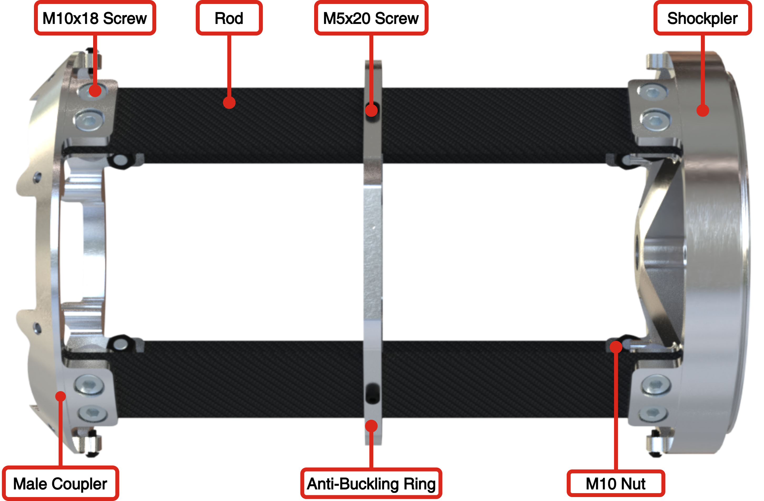
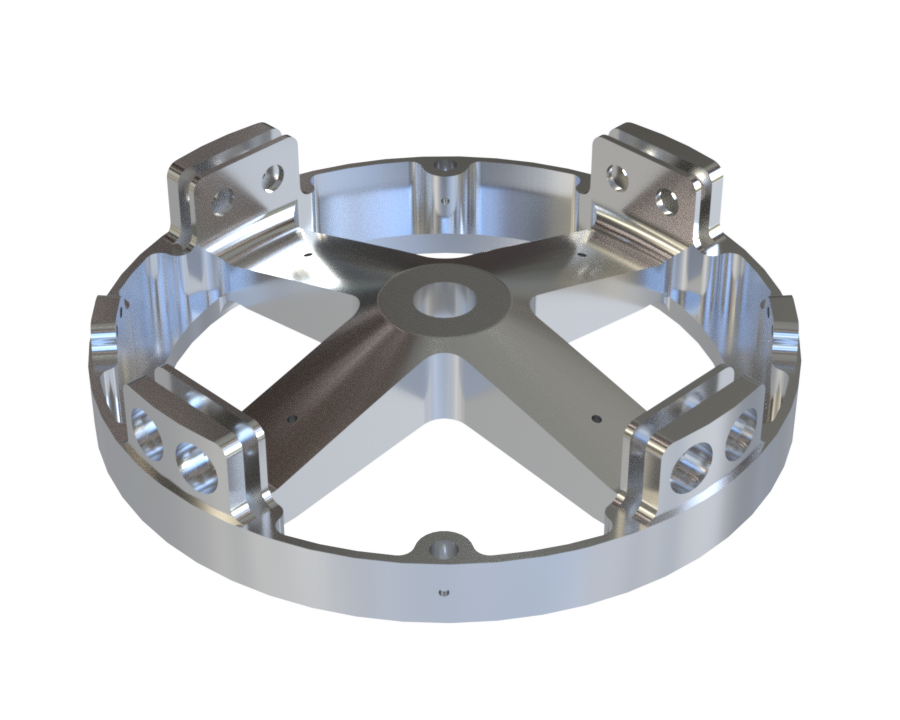
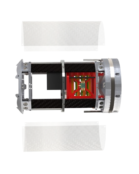
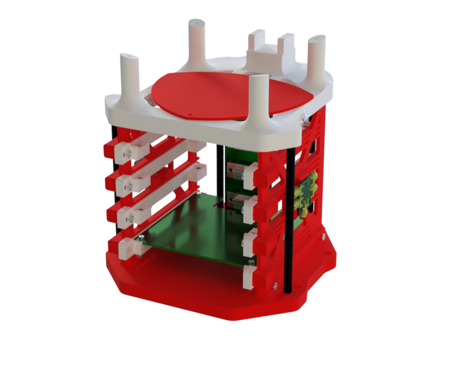
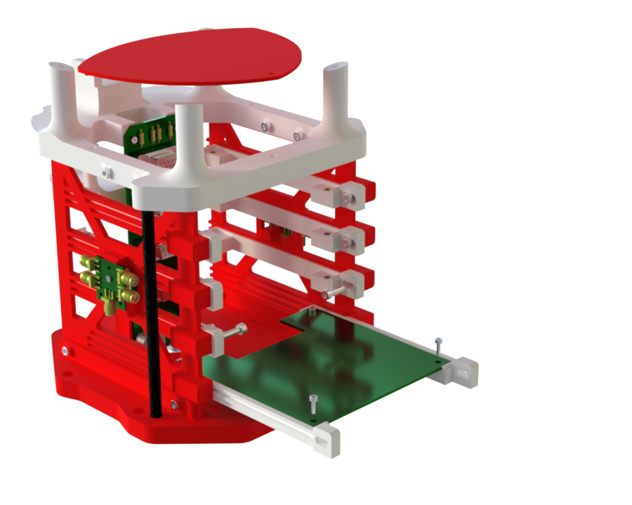
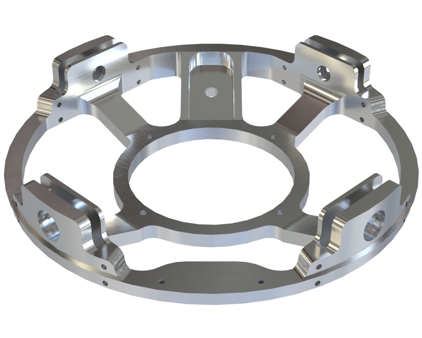
¶ Avionics-Bay
|:---:---
| |
|  |
|
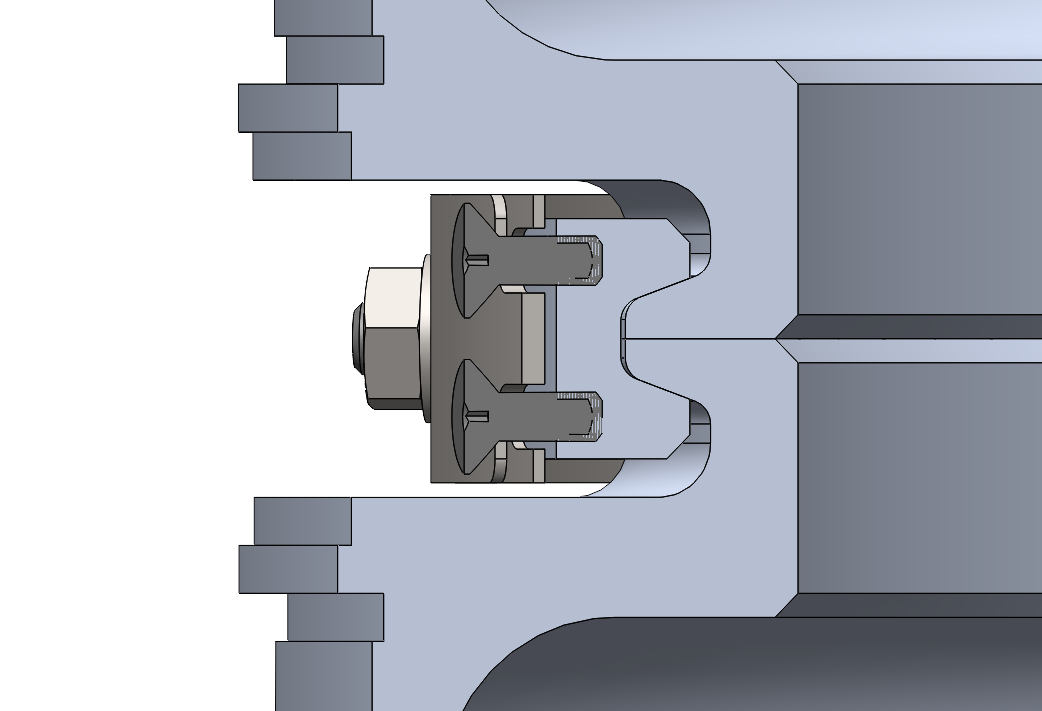
¶ Description
The Avionics Bay is very similar to the others: it includes 4 rods, a male coupler, and an ABR screw together.
It differs in the following aspects: it contains a Shockpler to connect it to the separation mechanism, and its panels are made of fiberglass.
The AIS is axially fixed to the Shockpler with four through-bolts and radially constrained by a 3D-printed ring interlocked with the ABR at four points. Its angular orientation depends on payload team's camera. Antennas are mounted on the ABR (nut-and-bolt fasteners) and MPS (inserts with nuts), while an M8 ring is screwed on top of the Shockpler.
¶ Main Specifications
| Specification | Value | Unit |
|---|---|---|
| Dimensions | 422 | [mm] |
| Mass | 5110.3 | [g] |
| Design Load (tensile) | 78'000 | [N] |
| Materials | CFRP / GFRP / Al-2050 / PETG | |
| Manufacturing | Prepregs / Infusion / 5-axis CNC / 3D-printing |
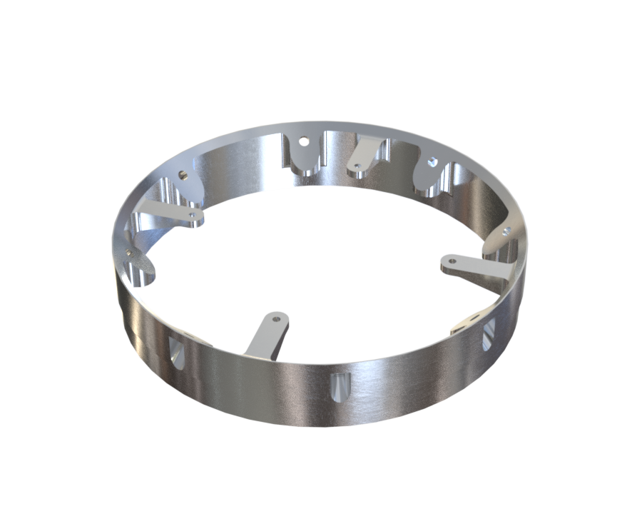
¶ Pressurant-Bay
¶ Description
¶ Main Specifications
| Specification | Value | Unit |
|---|---|---|
| Dimensions | 756 | [mm] |
| Mass | 4257.8 | [g] |
| Materials | CFRP / Al-2050 | |
| Manufacturing | Prepregs / 5-axis CNC |
¶ Tanks
¶ Description
The tanks are the parts of the rocket that contain the rocket engine's fuel and oxidizer. This year the rocket is equiped with a bi-liquid engine, and therefore two tank modules are required. One tank is filled with LOx at -183[°C], while the other is filled with Ethanol. The two propellants are pressurised at 60[bar] using nitrogen gas. Furthermore, the tanks are structrual parts of the rocket which mean they shall withstand all the flight loads and constraints. To facilitate manufacturing, both tanks are identical in terms of capacity and design. Both ends of each one are also identical so that only one type of cap is produced. The caps and tubes are made of Al-6082T6 and are welded together.
¶ Main Specifications
| Specification | Value | Unit |
|---|---|---|
| Dimensions | 243 x 243 x 454.6 | [mm] |
| Capacity | 16 | [L] |
| Mass | 7979 | [g] |
| Design Load | 120 | [bar] |
| Nominal pressure | 60 | [bar] |
| Test pressure | 90 | [bar] |
| Material | Al-6082T6 | |
| Manufacturing | 5-axis CNC / Turning / TIG Welding |
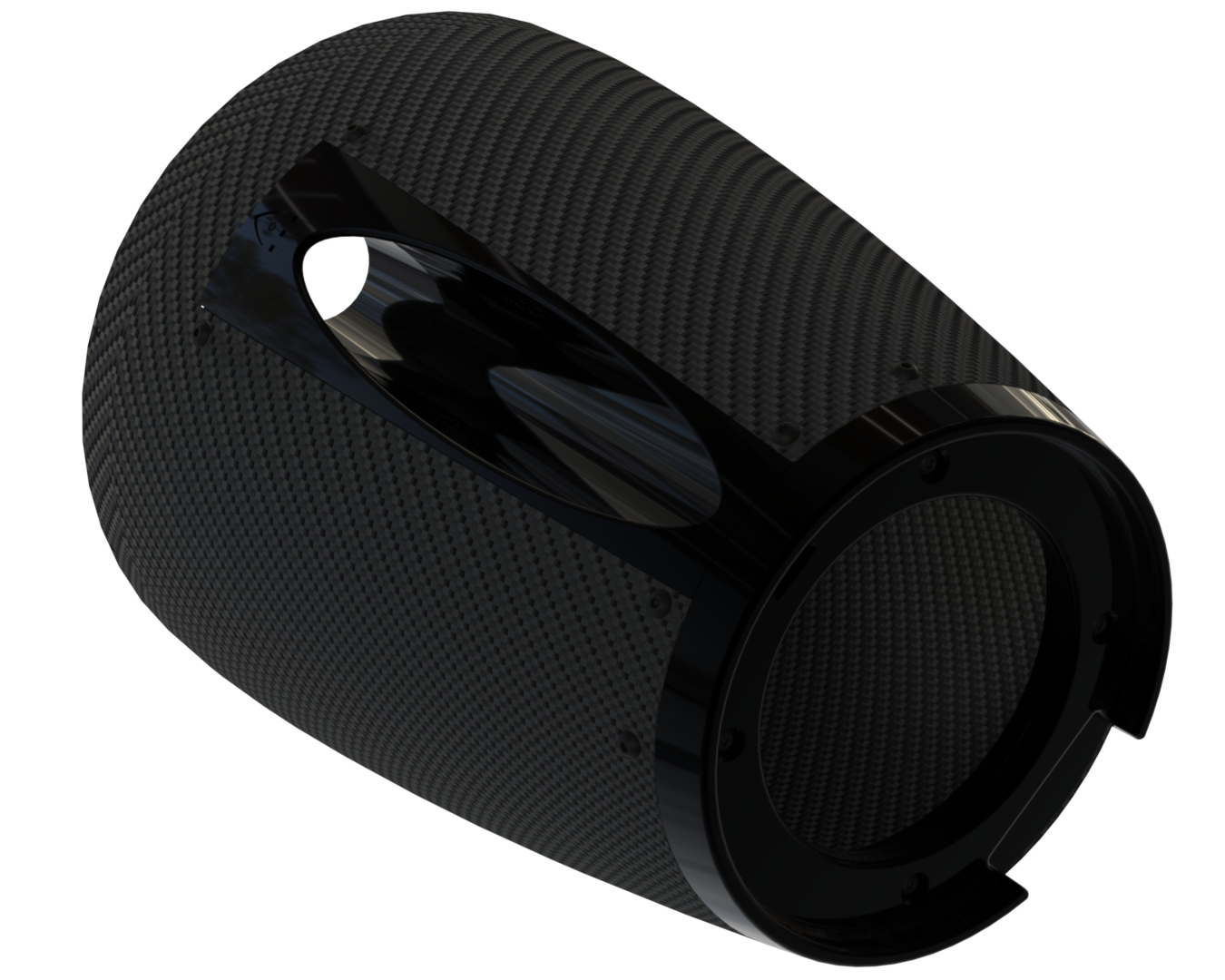
¶ Engine-Bay
¶ Description
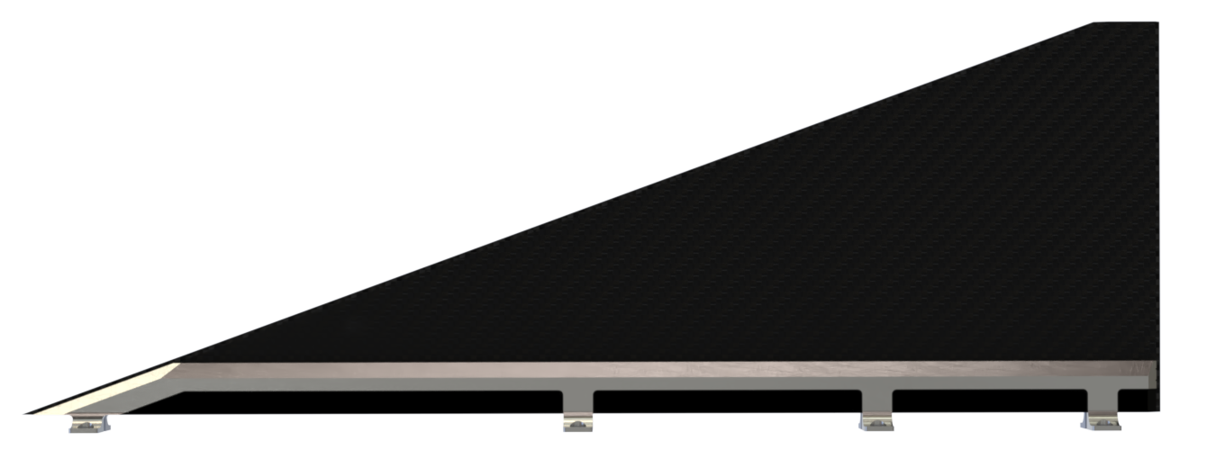
The Engine Bay is the main structure that integrates and transmits the thrust of Demo-B1 through the internal structure of Firehorn. It houses the bi-liquid engine, extending from both tanks to the lower section of the rocket, where it connects to the combustion chamber, ending with the boattail. The four fins are bolted to the bay's rods.
Note that the hold-down system for lift-off is connected to the boattail and secured to the thrust plate.
// IMAGE
¶ Main Specifications
| Specification | Value | Unit |
|---|---|---|
| Dimensions | 1020 | [mm] |
| Mass | 9100 | [g] |
| Design Load (compression) | 15'000 | [N] |
| Materials | CFRP / Al-2050 / Al-7050 | |
| Manufacturing | Prepregs / 5-axis CNC |
¶ Technical Budget, Margins and Deviation
¶ Length
| Module | Requirement [unit] | Measurement (worst case with error) [unit] | Delta [%] | Pass/Fail |
|---|---|---|---|---|
| Nosecone Bay | <1000[mm] | 1003[mm] | +0.3[%] | Pass |
| Recovery Bay | <700[mm] | 715[mm] | +[%] | Pass |
| Avionics Bay | <350[mm] | 422[mm] | +20[%] | Pass |
| Pressurant Bay | <700[mm] | 756[mm] | +8[%] | Pass |
| ETH Tank | <650[mm] | 388[mm] | -40.3[%] | Pass |
| Mid Bay | <280[mm] | 334[mm] | +19[%] | Pass |
| LOX Tank | <650[mm] | 388[mm] | -40.3[%] | Pass |
| Engine Bay | <720[mm] | 756 [mm] | +8[%] | Pass |
| Boattail | <[mm] | 288 [mm] | +[%] | Pass |
¶ Mass
| Module | Requirement [unit] | Measurement (worst case with error) [unit] | Delta [%] | Pass/Fail |
|---|---|---|---|---|
| Nosecone Bay | <3200[g] | 1855.5[g] | -42[%] | Pass |
| Recovery Bay | <6000[g] | 3259[g] | -45[%] | Pass |
| Avionics Bay | <6000[g] | 5110.8[g] | -14.8[%] | Pass |
| Pressurant Bay | <6000[g] | 4258.3[g] | -29[%] | Pass |
| ETH Tank | <10100[g] | 8300.5[g] | -17.8[%] | Pass |
| Mid Bay | <3800[g] | 2666.2[g] | -29.8[%] | Pass |
| LOX Tank | <10100[g] | 8300.5[g] | -17.8[%] | Pass |
| Engine Bay | <7000[g] | 9100 [g] | +30[%] | Pass |
| Aerocover | <1000[g] | 160 [g] | -84[%] | Pass |
¶ Design Constraints
¶ Constraints for Production
¶ Composite Parts
Most of the composite parts are manufactured at the LPAC in the EPFL Campus. This workshop allows to perform wet lay-up and infusion techniques for any parts as long as we bring the appropriate mould.
The latter can be machined from epoxy toolbox or MDF using a 3-axis CNC from the SKIL Workshop (EPFL Campus). Else, the mould can be 3D-printed at the 3D-printing facilities of the SPOT (EPFL Campus).
The LPAC has an autoclave which can hosts parts <700mm, allowing to form high performance prepregs composites.
Large prepregs parts (>700mm) are manufactured at APCO Technologies. They provide an autoclave which could easily host a car.
Nonetheless, manufacturing session at their workshop requires thorough preparation. The session lasts at most a week (working days only).
Composite cutting can be done manually at the LPAC or by water-jet at the ATMX Workshop (EPFL Campus).
¶ Aluminium Parts
Most of the aluminium parts are manufactured at the ATME Workshop (EPFL Campus).
Large parts such as the tanks are machined at the PLTE Workshop (EPFL Campus). They also do welding on steel and aluminium if required.
¶ Constraints for Operation
The airframe is integrated once every other sub-systems are done with their integration.