¶ Introduction
This document presents the general design chosen for the internal structure of the rocket.
The internal structure is the assembly responsible for the structural integrity of the rocket. It keeps all the subsystems together and takes up the loads applied to the rocket.
The internal structure will be present inside the avionics bay, the pressurant bay and the engine bay.
¶ Definitions and Abbreviations
- PR : Propulsion
- AV : Avionics
- ST : Structure
- ABR : Anti-Buckling Ring
- FoS : Factor of Security
- ERT : EPFL Rocket Team
- FH : Firehorn
- FH30 : Version of the Firehorn launch vehicle that will fly to a [30]km altitude
- CFRP : Carbon Fiber Reinforced Polymer
- FEA : Finite Elements Analysis
¶ Relevant Knowledge Needed
This internal structure is present throughout most of the launch vehicle, it is not a particular module, but a design type.
Being a key system of the rocket, it is subject to a certain number of requirements.
Engineering Requirements
- Compatible for the 9km and 30km versions of the rocket.
- Resists the flight loads (mostly bending, traction and compression).
- Easily scalable for each module needs.
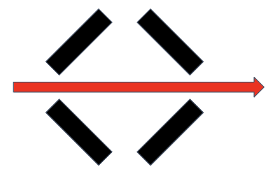
- Quad-symmetric.
- Offers modularity (additionnal 3D printed part can be attached to it).
- Offers high accessibility (for PR plumbing and AV antennas).
- 2024_C_SE_ST_REQ_07 Diameter reduction
The reduced inner diameter due to CPLR/separation mechanism/structure design shall be greater than [160][+10/-0] mm. - 2024_C_SE_ST_REQ_08 LV inside diameter
The LV shall have an internal diameter of [200][+/-0.25]mm. - 2024_C_SE_ST_REQ_10 Parachute opening decelleration
The ST shall withstand a tensile acceleration of [30]g applied on the parachute's attachment points with an additional FoS of [3]
The internal structure must withstand the following loads:
- Traction of [30]g with a FoS of 2.
- Compression of [10]kN with a FoS of 2.
- Flexion (3-point bending along the rocket) of [4500]N with a FoS of 2.
¶ General Design
As the design of the internal structure of the previous rocket Nordend proved to be very resilient and practical, it was decided from the start that a similar design would be used for Firehorn.
We therefore kept the general idea of the structure and adapted it to the new loads and requirements.
¶ Conception Flux Diagram
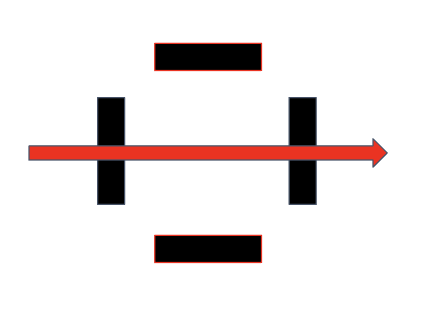
The internal structure is composed of modules identical in composition, but of different length. A typical module of Nordend is shown above.
It consists of four CFRP rods distributed so as to respect quadrisymmetry, held on each side by couplers. Anti-buckling rings are distributed throughout the CFRP rods.
Rods
- Take on all the loads of the rocket.
- Made of Carbon Fiber Reinforced Polymer (CFRP).
Couplers
- Hold the rods.
- Allow to assemble the different modules/parts of the rocket together.
- Usually made of aluminium alloy.
Anti-buckling rings
- Distributed along the rods.
- Prevent rods from buckling during compression.
Main Advantages: resilient, easily adaptable to needs, provides easy access to components inside the rocket, takes up little space, easy to assemble.
Main Disadvantages: heavier than a tube, some parts can be expensive to produce.
¶ Ears
The ears are present on the couplers and are used to clamp the rods as shown in the image (example from Nordend).
A representation of the assembly rods/ears is shown below:
The rods are held exclusively by friction, the screws are only here to apply pression between the ears and the rods. It is therefore necessary to design them according to the forces applied to the rods.
Knowing that the traction force of [30]g is the most important constraint that will be applied, we can calculate the normal force needed to maintain the rods by friction. The approximate dry mass of the [30]km launch vehicle of [100]kg is used for this load case.

¶ Design options
To satisfy this pressure on the rods, several designs are possible.
The design option that will be used for Firehorn has not yet been defined.
For all options, screws with low head socket cap (DIN 7984) are considered, with a property class of 10.9.
This option considers the use of two screws of size M8.
Minimum rods width: 50[mm]
Minimum ear height: 20[mm]
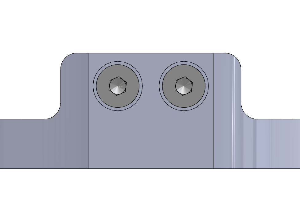
Main advantages: Low ears so the couplers will be cheaper to produce, easy to assemble.
Main disadvantages: Low redundancy, thick screws so exceed the integration diameter by 2.5mm.
This option considers the use of four screws of size M6.
Minimum rods width: 40[mm]
Minimum ear height: 27.5[mm]
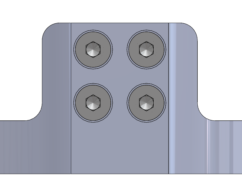
Main advantages: Redundancy, narrow rods.
Main disadvantages: High ears so the couplers will be more expensive to produce, exceed the integration diameter by 0.95mm.
This option considers the use of six screws of size M5.
Minimum rods width: 47.5[mm]
Minimum ear height: 23[mm]
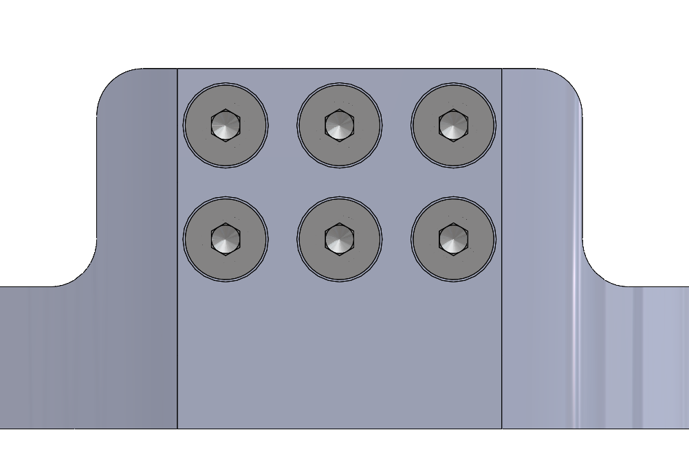
Main advantages: Redundancy, low height (parts cheaper to produce), thin screws -> closest option to satisfy the integration diameter requirement.
Main disadvantages: Longer to assemble.
¶ Rods
The rods' role is to support the forces applied on the rocket, these forces include traction, flexion and compression
¶ Material Properties
CFRP rods are characterized by their remarkable strength-to-weight ratio, corrosion resistance, and flexibility. These properties stem from the synergistic combination of carbon fibers' high tensile strength and stiffness with the polymer matrix's durability.
The rods will be composed of a superposition of 22 layers, made from UD carbon or woven carbon.
Each layer is composed as follows: [[0UD, 45W, 0UD, 45W, 0UD, 45W, 0UD, 45W, 0W, 45W, 0W]SE].
The properties of the UD and woven carbons are detailed below:
| Material | Density [t/mm3] | E1 [MPa] | E2 [MPa] | E3 [MPa] |
|---|---|---|---|---|
| Carbon UD | 1.6e-9 | 1.64e5 | 1.17e4 | |
| Carbon Woven | 1.57e-9 | 6.65e4 | 6.65e4 | 1.e4 |
| Material | Nu12 | Nu13 | Nu23 | G12 [MPa] | G13 [MPa] | G23[MPa] |
|---|---|---|---|---|---|---|
| Carbon UD | 0.316 | 5.5e3 | 5.5e3 | 5.5e3 | ||
| Carbon Woven | 0.05 | 0.35 | 0.35 | 5e3 | 4.5e3 | 4.5e3 |
| Material | Tensile stress, fiber direction [MPa] | Compressive stress, fiber direction [MPa] | Tensile stress, transverse direction [MPa] | Compressive stress, transverse direction [MPa] | Shear stress [MPa] |
|---|---|---|---|---|---|
| Carbon UD | 2720 | 1690 | 64 | 304 | 120 |
| Carbon Woven | 800 | 924 | 800 | 924 | 79 |
¶ Simulations
The simulations presented aim to determine the size of the rods in both width and thickness
The height of the rods is a constant at [1200]mm which is the maximum height for the pressurant bay under the 30k launch
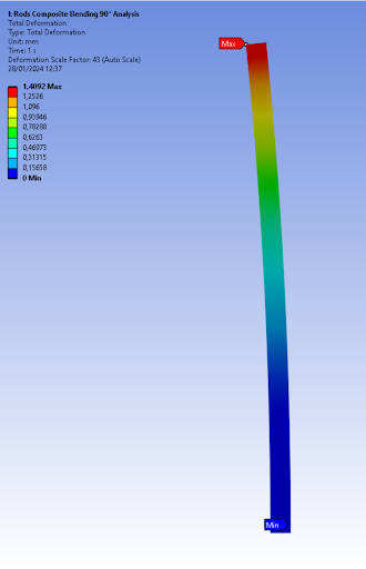
Load case:
Axial force : 15'000 [N] , which can decomposed with : 100 [kg] x 30 [g] x 2 [-] / 4 [-]
Dry mass of FH30 decelerated at 30[g] with a FoS = 2[-], divided by 4 rods
Boundary conditions : one end is clamped, the other end is free
Safety factor analysis: Max: 1000 Min: 3.21
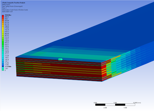
Deformation analysis: Max: 1,40 mm Min: 0 mm
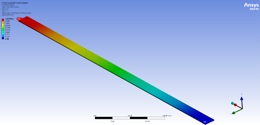
Conclusion: The safety factor is superior to 3 and the maximum deformation is less than 1.5 mm
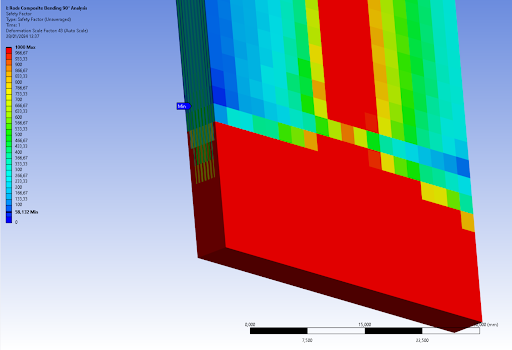
Load case: Lateral moment of 2625 [Nm] which can be decomposed with : 50[kg] x 3.5[m] x 3[g] x 2[-] / 4[-]
Half of the dry mass of FH30 accelerated at half of the width of the rocket at 3[g] with a Fos = 2[-], divided by 4 rods
Boundary conditions : one end is clamped, the other end is free
Diagram of the simulation:
Safety factor analysis: Max: 1000 Min: 18.7
Deformation analysis: Max : 61.0 mm Min: 0 mm
Conclusion: the safety factor is superior to 18 and the maximum deforation is 61 mm
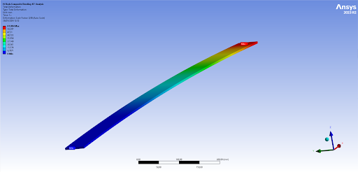
Load case: 5250 [Nm] which can be decomposed with : 50[kg] x 3.5[m] x 3[g] x 2[-] / 2[-]
Half of the dry mass of FH30 accelerated at half of the rocket at 3[g] with a Fos = 2[-], divided by 2 rods
Boundary conditions : one end is clamped, the other end is free
Diagram of the simulation:
Safety analysis: Max: 1000 Min: 58.1
Deformation analysis: Max: 1.4 mm Min: 0 mm
Conclusion: The safety factor is superior to 58, and the maximum deformation is less than 1.5 mm
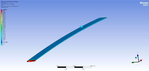
Load case: 5500[N] which can be decomposed with :10000[N] + AM[N] x 2[-] / 4[-]
Engine thrust of FH30 and the reaction force of the mass on top of the pressurant bay multiplied by the maximum acceleration during ascent of the LV, with a FoS = 2[-], divided by 4 rods
Boundary conditions: Both ends are clamped, with 4 anti-buckling rings simulated by rollers
Safety analysis: Max: 1000 Min: 5.5
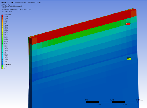
deformation analysis: Max: 0.5 mm Min: 0 mm
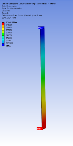
Buckling:
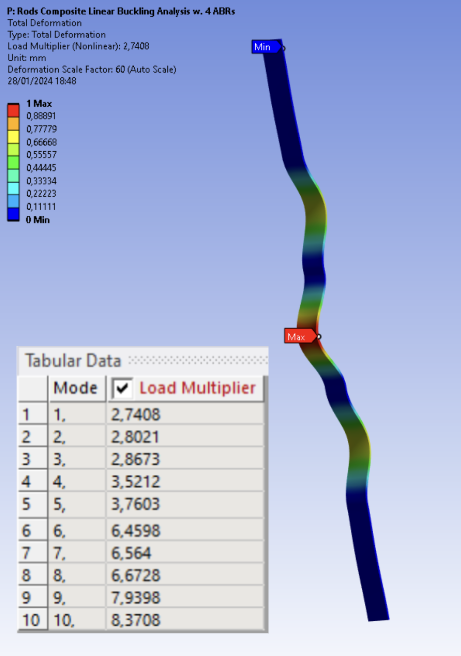
Conclusion: Safety factor minimum is superior to 5.5, the maximum deformation is 0.5 mm, and the load multiplier for the first buckling mode is 2.7
The structural integrity of the rods can be validated for all the simulations
¶ Anti-buckling Ring
The anti-buckling rings are designed to prevent the CFRP rods from buckling during the launch. They will be strategically distributed along the length of the rods.
¶ Design
For now, the anti-buckling rings used for Firehorn are a scale-up of the Nordend's ones since their design proved to be effective.
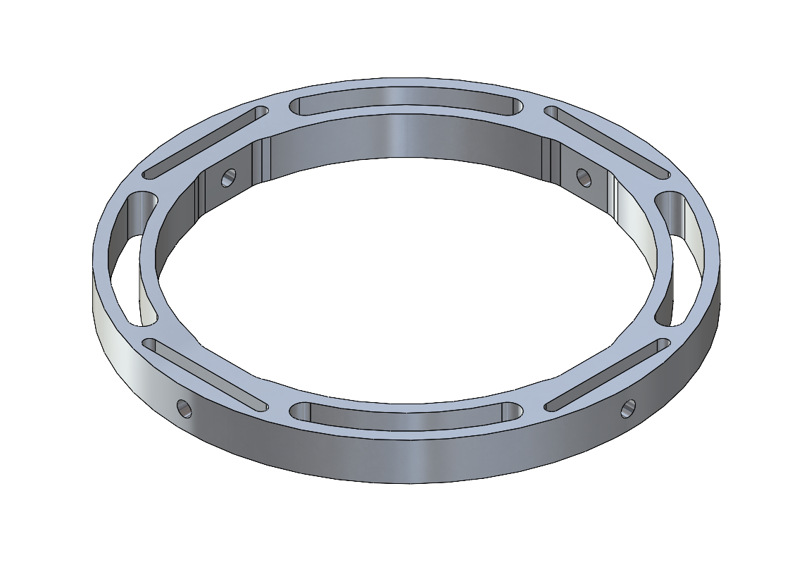
Main advantages: Lightweight design, easily adaptable to Firehorn's internal structure, easy to manufacture, resilient design.
Main disadvantage: small contact surface so we will need many ABRs on Firehorn.
If necessary, this design will have to be adjusted in order to take into account any defects or incompatibilities that may be encountered during the rest of the rocket development process.
¶ Number of rings
The rods FEA simulations shown above confirmed that four ABRs for the pressurant bay of the 30km rocket version are sufficient to prevent the rods from buckling.
We can use this information to estimate the number of ABRs necessary for the different modules of the 9km version of the rocket. Simulations will later be performed to ensure these estimates are correct.
One ABR will be required for the AV Bay.
Three ABRs will be required for the pressurant bay.
One ABR will be required for the mid bay.
Two ABRs will be required for the engine bay.