¶ Goals of the study
This comparative simulations study was done to investigate the impact of the anti-buckling-ring and coupler ear area on the buckling performance of the Firehorn internal structure carbon rods.
In particular, simulations were performed to investigate:
- If an increase of the coupler ear height increases the performance in buckling (bottom orange area in image below)
- If an increase of the anti buckling ring height increases the performance in buckling (top orange area in image below)
- If the center area of the anti buckling rings can be removed (to reduce the mass) without significantly reducing the performance in buckling (red area in image below)
¶ 2111XX_ROD
¶ Geometry
This study analyses the performance of the carbon rods of the Firehorn internal structure which are displayed below.
For this study, a generic rod of 600[mm] total length is considered. Note that this rod doesn't correspond to a particular Firehorn module. Moreover, the ear and anti-buckling-ring clamping area dimensions do not exactly correspond to the parts used on Firehorn.
This is because this study is meant to be comparative and not to exactly quantify the performance of the exact Firehorn structural modules.
¶ Function
As the structural backbone of the internal structure and of the launch vehicle, the carbon rods transmit and withstand all main flight and operation loads from the engine bay up to the recovery bay.
¶ Material
The carbon rods are made of the following materials:
Epoxy based CFRP from Hexcel (HexPly©)
| Denomination | Prepreg | Type | Expected real thickness [mm] |
|---|---|---|---|
| a | EH25/34%/UD136/HTA-12K | UD | 0.14 |
| b | W3T-282-42'-F593-14 | Plain | 0.21 |
Lay-up: [45b, 03a, 45b, 02a, 45b]2s
Expected real thickness: 5.32mm
¶ Load case
The load case considered for this study is the buckling induced by the compressive load. Because a single rod is considered, the force is divided by 4 and a compressive load of 3750[N] is applied.
- 2024_C_SE_ST_REQ_31 ST Load Case - Axial compression
The structural load-bearing elements shall withstand axial compression loads of [10000]N with a FoS of [1.5]. - 2024_C_SE_ST_REQ_35 ST Load Case - Buckling
The structural load bearing elements shall withstand buckling caused by the axial compression load case.
¶ Finite Element Analysis
¶ Software
ANSYS Workbench (2023R2) is used for this study. ANSYS ACP is used to create the solid composite and ANSYS Mechanical is used for the static structural analysis.
¶ Type of simulation
For this study, a linear eigenvalue buckling analysis is performed from a pre-loaded static structural analysis in compression.
¶ Inputs
The length units are changed from m to mm, resulting in the following set of units: mm-kg-N-s-mV-mA
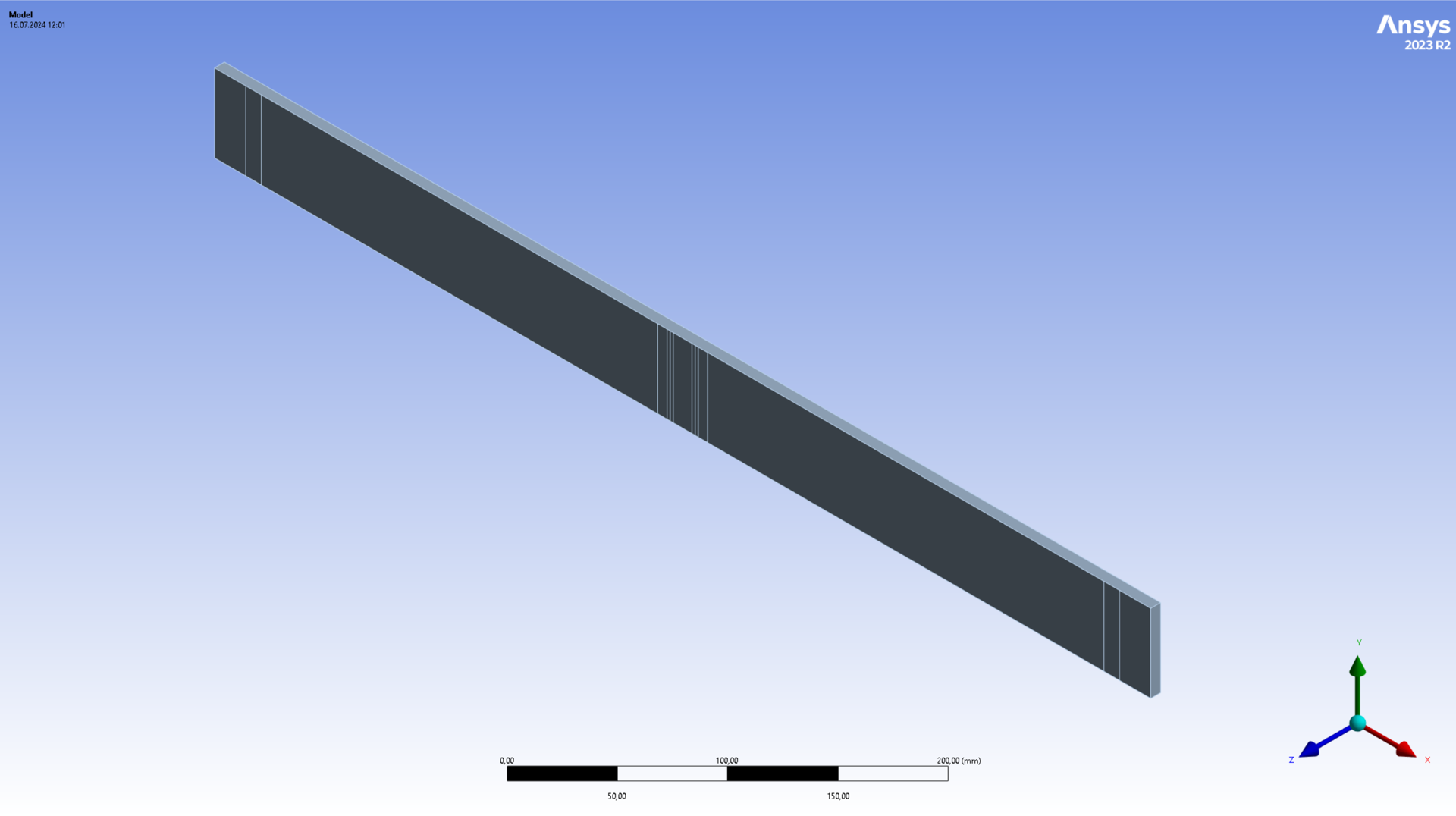
The rod used for this study has its area split into multiple smaller areas to be able to use different boundary conditions. All dimensions are included in the following picture in mm. The rod width is given as an output of the ANSYS ACP module. The geometry is simplified by neglecting the holes present on the actual rods to allow the screws to pass through them.
A full 3D solid model is transferred from ACP to Mechanical (instead of transferring the resulting shell body). The corresponding solid body is displayed below and corresponds to the previously established dimensions.
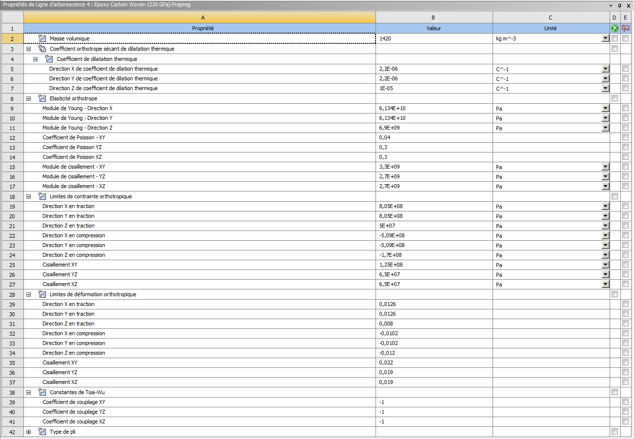
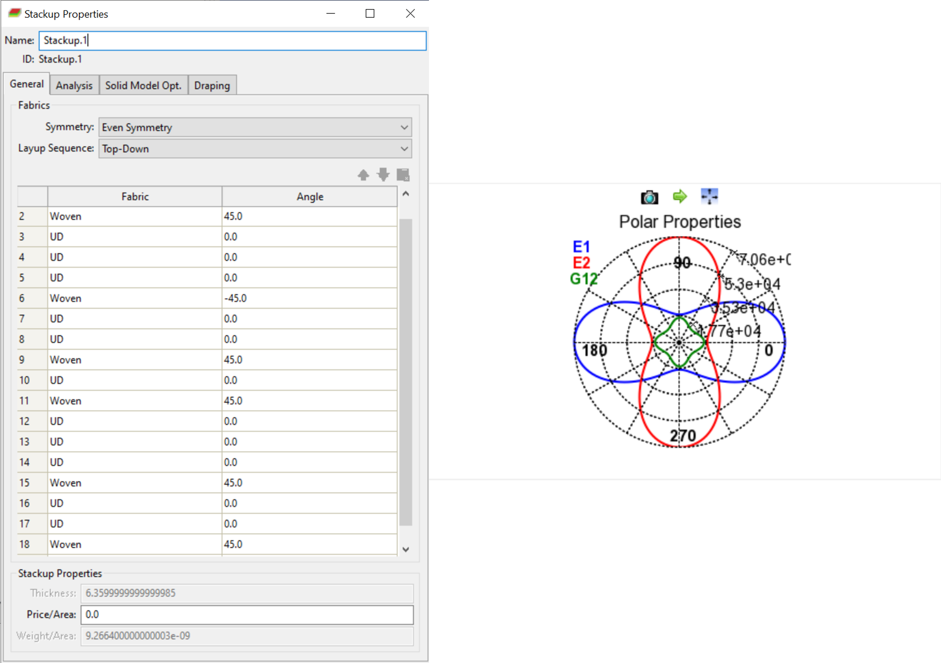
The 3D solid elements are generated in ANSYS ACP by recreating the carbon layup used in the Firehorn rods. However, since this is only a comparative study and not a quantitative analysis, some generic options for prepreg UD and Woven fibers are taken from the ANSYS material database instead of using the actual properties of the UD and Woven carbon used for Firehorn. This means that the rods used in this study likely outperform the rods produced for Firehorn.
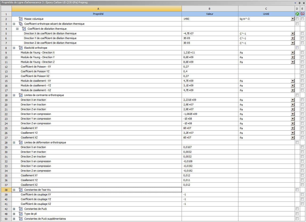
The carbon properties are taken directly from the ANSYS database and are displayed below (1st image is woven, 2nd is UD).
The third image displays the selected thickness for the 2 types of carbon layers.
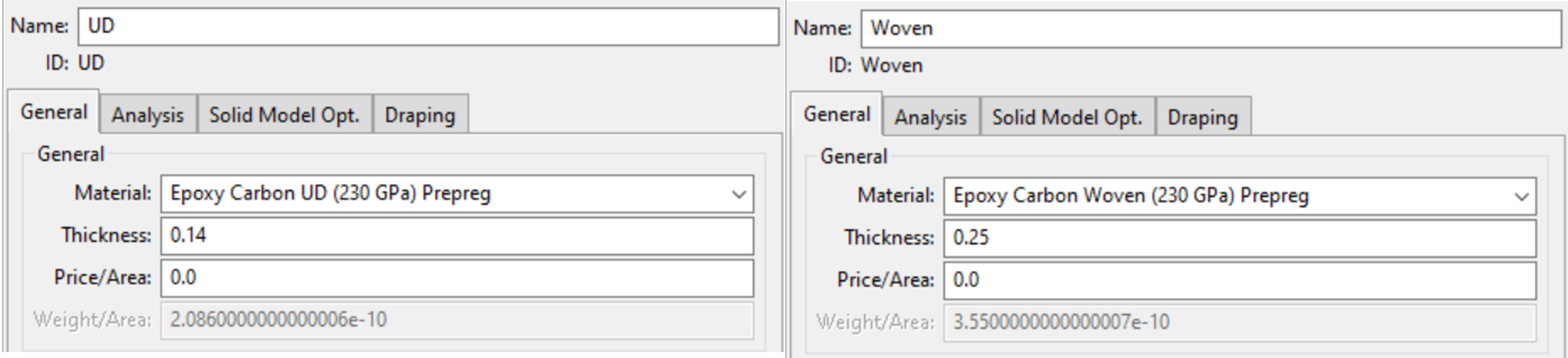
The fourth image displays the selected stackup corresponding to the rods produced for the first Firehorn Launch Vehicle, and its corresponding properties. Note that the 'symmetry even' option was selected.
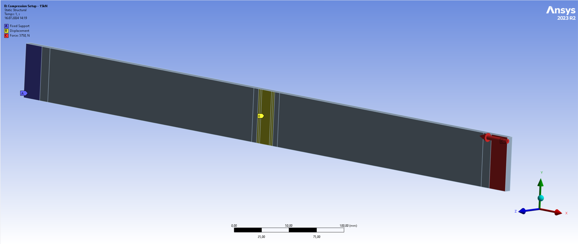

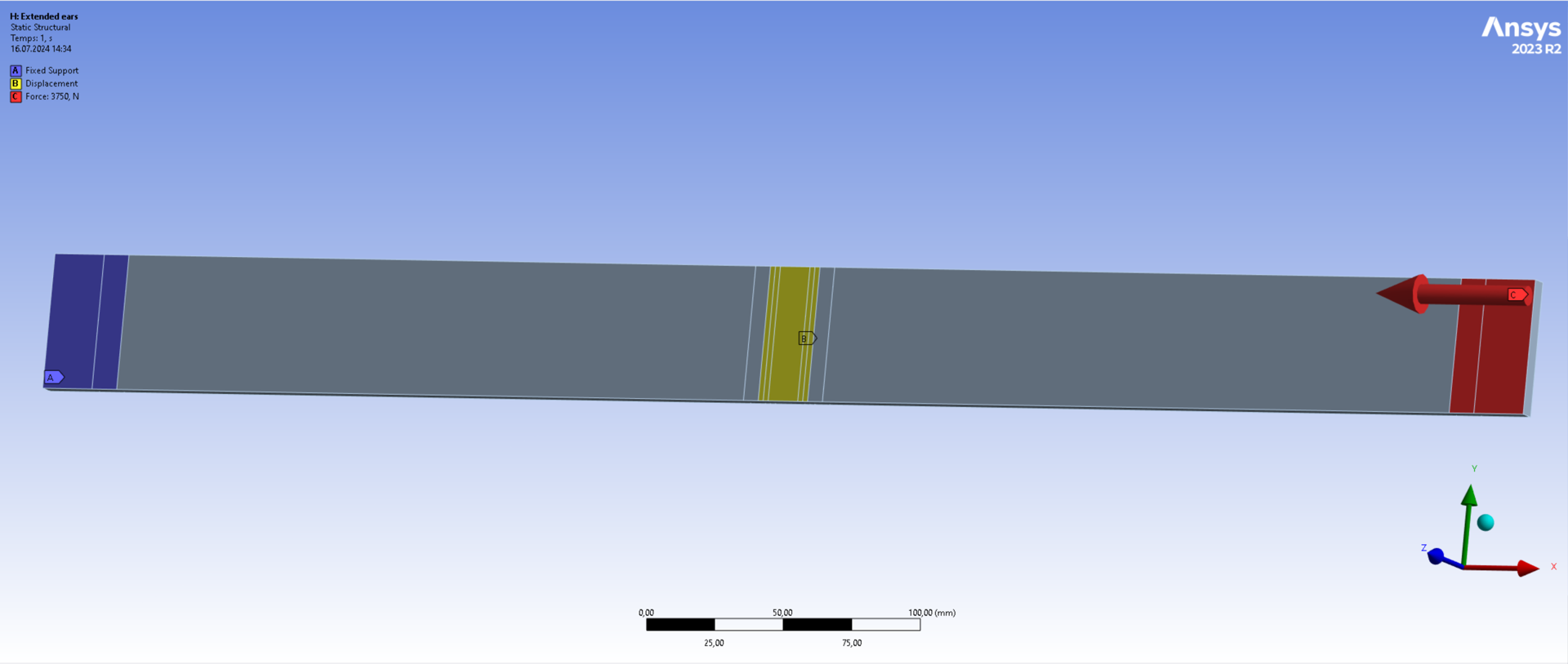
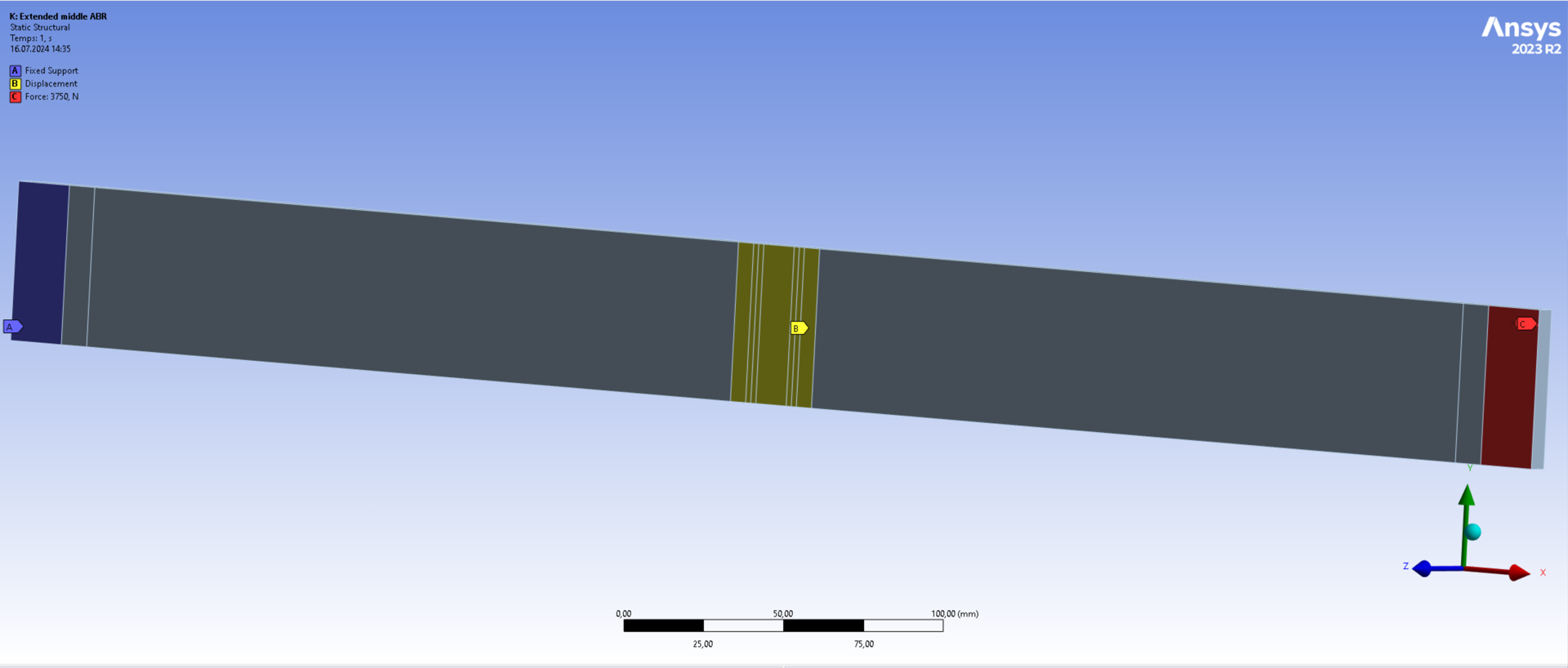
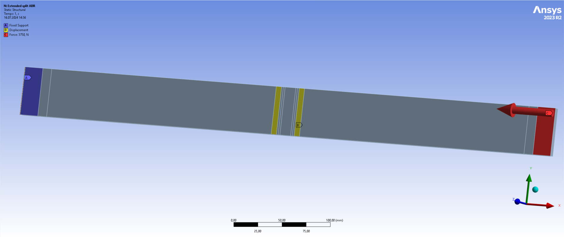
This study is split into 5 different analysis cases, of all which have different boundary conditions. For all cases, the same types of BCs are applied, but the point at which they are applied changes:
| Color: | Blue Area | Yellow Area | Red Area |
|---|---|---|---|
| BC Type: | Fixed support | Frictionless slider | Frictionless slider + load |
| Blocked DOFs: | (rotations + x,y,z) | (rotations + y,z) | (rotations + y,z) |
| Applied load: | / | / | F_x = -3750[N] |
For the static structural analysis, all default parameters are kept.
For the eigenvalue buckling analysis, negative load multipliers are excluded from the analysis, and the first 10 modes are extracted.
¶ Mesh
The element types are SOLID185 inside the solid body and SURF154 at the surface. The element order is left program controlled.
No particular refinement is applied. Only the global element size is used to generate the different meshes.
To refine the mesh, the load multipliers of the linear eigenvalue buckling analysis are chosen as the convergence criterion. In particular, the first load multiplier (eigenvalue) is considered, as it corresponds to the lowest buckling load, and is therefore well suited to evaluate buckling resistance.
The baseline case is used to verify mesh independance.
The 'size' quantity refers to the global element size setting used to generate the mesh.
| Size [mm] | 2 | 1 | 0.5 |
|---|---|---|---|
| 1st load multiplier [-] | |||
| Deltas [%] | / |
We can therefore conclude that the mesh with 2[mm] global size elements is sufficiently accurate for this analysis. It was decided not to use a coarser mesh because, as was displayed in the 'geometry modelling' section, some surfaces used to generate the boundary conditions are 2[mm] wide. Therefore, using elements larger than the BC area could induce problems that were better to avoid altogether, at the cost of more computation time.
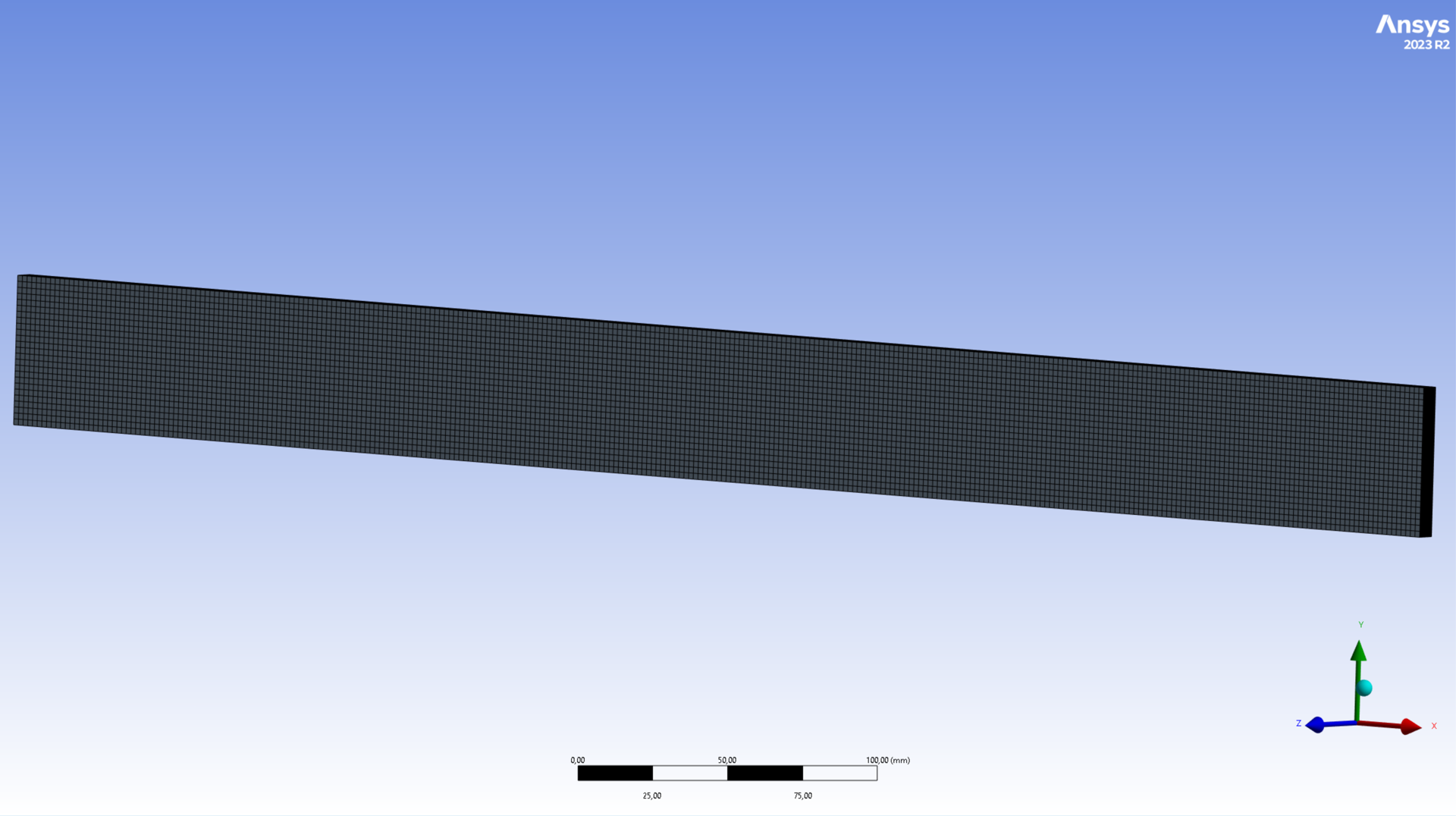
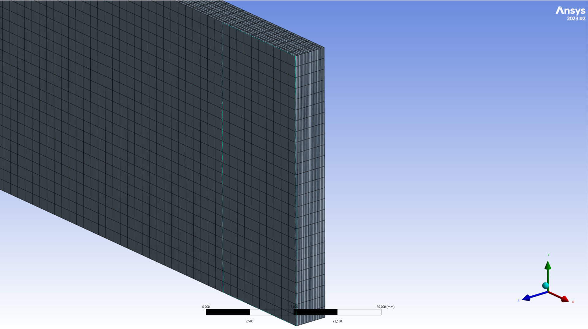
The final mesh is the one generated with a global element size of 2[mm]. It contains 270000 elements. The average element quality is low (16%) due to the high cell aspect ratio. This is however typical of meshes produced by ANSYS ACP and isn't considered an issue.
The following two images display the final mesh.
¶ Outputs
The only quantitative outputs considered for this study are the buckling load multipliers. They are defined as:
where is the loading buckling force (in this case 3750[N] in the direction) and is the 't buckling load extracted by the linear eigenvalue buckling analysis ( > 1 means that the analysis predicts no buckling in the linear regime). The load multipliers are unitless ().
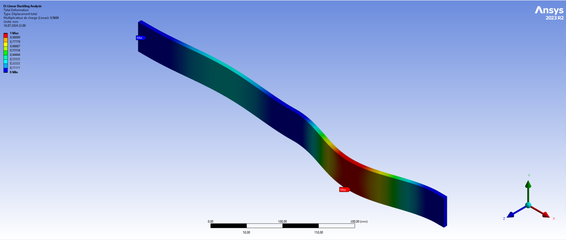
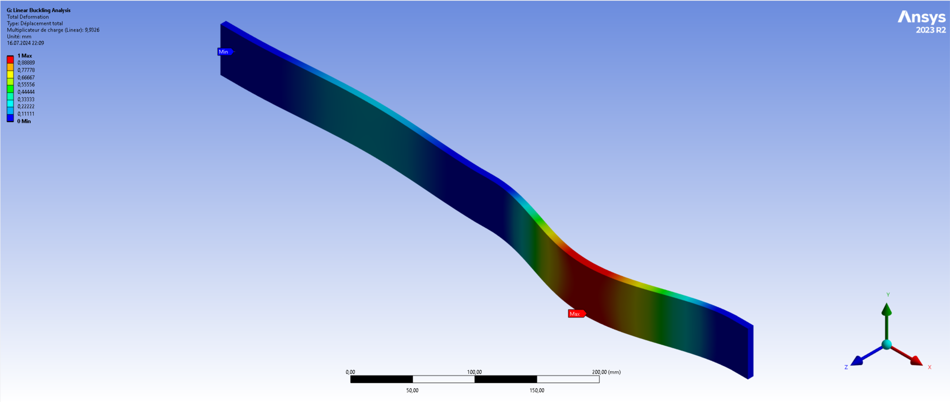
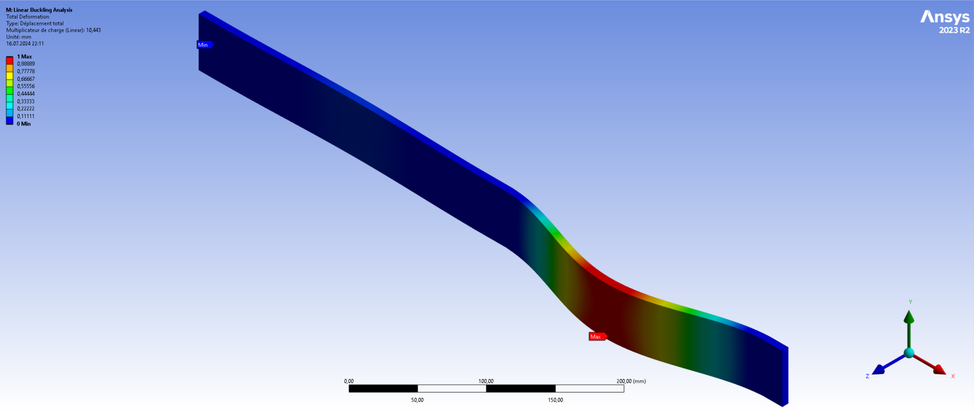
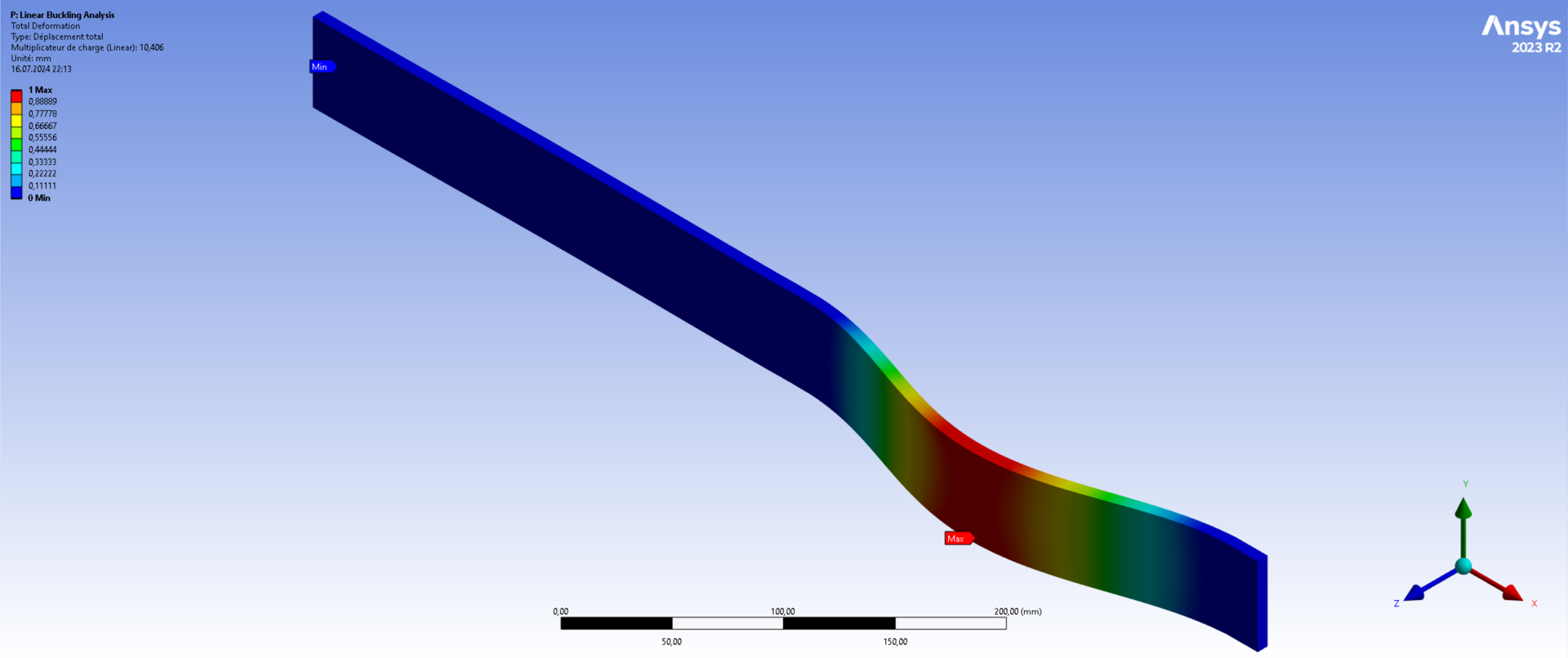
As a qualitative output, the first buckling mode of each configuration are also extracted.
¶ Load multipliers
Although 10 modes were extracted for each case, only the first mode is of interest to compare the configurations as this is the lowest load where buckling occurs.
| Analysis case | |
|---|---|
| Baseline | 9.96 |
| Split ABR | 9.93 |
| Extended ears | 10.69 |
| Extended ABR | 10.44 |
| Extended split ABR | 10.40 |
¶ Buckling modes

¶ Interpretation
¶ Simulation validity
To validate the results of the simulation, the Euler buckling theory can be used on the baseline case. The euler buckling load is given by
For the baseline case, the parameters are:
| Variable | Parameter | Value |
|---|---|---|
| Young modulus | [] | |
| 2nd moment of area | E-9[] | |
| Buckling wavelength | [] | |
| Column length | [] |
where is given by ANSYS ACP and corresponds to clamped-clamped beams. [mm] corresponds to one half of the rod: Looking at the first eigenmode shows that almost all buckling occurs on a single half.
This gives the following results:
| Variable | Theoretical value | Simulation result | Delta [%] |
|---|---|---|---|
| P_ | 40881[N] | 37350[N] | -8.64 |
| 10.9[-] | 9.96[-] | -8.64 |
The main sources of error with the theory can come from modelling errors, from the fact that Euler Buckling Theory was derived for isotropic materials while this analysis is based on an orthotropic solid, and from the fact that a little bit of buckling also occurs in the second half of the rod, which wasn't considered in the theoretical calculations. It can therefore be concluded that the simulations results are coherent and verified.
¶ Conclusions
¶ Initial questions
- If an increase of the coupler ear height increases the performance in buckling
- If an increase of the anti buckling ring height increases the performance in buckling
- If the center area of the anti buckling rings can be removed (to reduce the mass) without significantly reducing the performance in buckling
Simulation results show that increasing the ear area by has increased the buckling load multiplier by [-]. This is a significant increase and shows that a potential tradeoff exists between additional ear mass and higher structural performance, which was evident for pure traction, but is now also made clear for buckling.
Simulation results show that a increase in the ABR height has increased the buckling load multiplier by . This is a less significant improvement than for the increase in the ear height. This indicates that the tradeoff between mass increase due to ABR height increase and improvement in buckling might not be worth considering.
The 2nd and 5th simulation results show that splitting the ABRs and only clamping the rod at its extremities virtually has no impact on the bukling performance of the assembly. This indicates a significant potential for mass reduction in the ABRs. Nevertheless, such reductions in the ABR mass must be made such that the stress applied by the rod on the ABR remains acceptable due to the lower contact area.
¶ Reasoning
This study indicates that, for the considered cases, the main factors in improving buckling performance are:
- Reduction in rod unclamped length
- Reduction of the buckling wavelength
In particular, it seems that, for thin ABRs, it doesn't matter much exactly how thick the ABR is, just that it is there to restrict the wavelength.
When the ABRs are split and their center contact area is removed, the rod unclamped length and the forced buckling wavelength remain the same, thus the similar results to the 'full' ABR case.
¶ Further work
In order to increase certainty with the fact that no buckling can occur inside of the ABR for the 'split ABR' case, either nonlinear buckling simulations or testing can be done. Both are difficult and require time and expertise. It is believed that the current analysis is accurate enough, and that further work isn't worth the potential increase in certainty. Therefore, no further work is recommended on this topic.