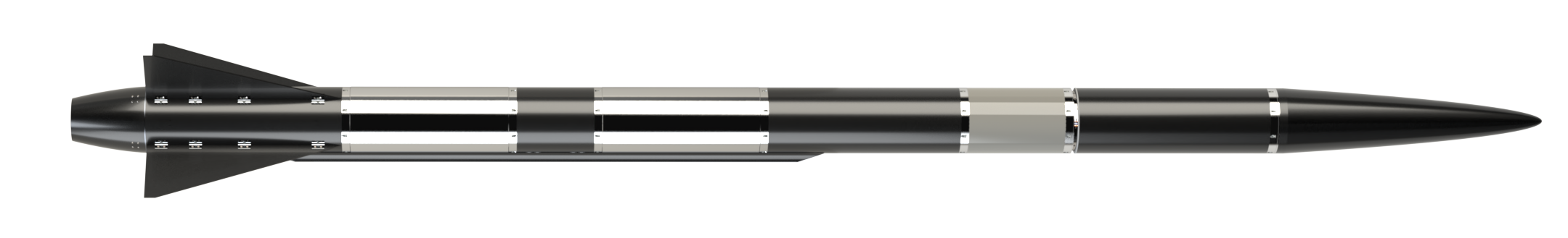
¶ 211101_Nosecone
¶ Geometry
¶ Function
The nosecone of the vehicle shall reduce the drag as well as hosting the payload.
¶ Material
Epoxy based CFRP from Hexcel (HexPly©)
| Prepreg | Type | Thickness [mm] |
|---|---|---|
| W3T-282-42'-F593-14 | Plain | 0.24 |
Lay-up: [0, 45, 0]SO
Thickness: [mm]
¶ Load case
-
2024_C_SE_ST_REQ_31 ST Load Case - Axial compression
The structural load-bearing elements shall withstand axial compression loads of [10000]N with a FoS of [1.5]. -
2024_C_SE_ST_REQ_34 ST Load Case - Bending moments
The structural load-bearing elements shall withstand bending moments caused by the fins of up to [7500]Nm. -
2024_C_SE_ST_NOSECONE_REQ_10 Nosecone load case 1 - Deceleration
The nosecone shall withstand axial tensile loads caused by a deceleration of [30]g's applied on a dry mass of [8]kg, with a FoS of [2].
¶ Finite Element Analysis
¶ Software
Altair EsaComp: material properties
ABAQUS CAE: Meshing program
ABAQUS Standard: FEA
¶ Type of simulation
- Static structural
¶ Goal of the simulation
This analysis aims to validate the structural integrity of the final lay-up design proposed.
¶ Inputs
mmNS: mm-ton-N-Nmm-MPa-mm^4-mJ
Truncated cone
∅start = 24 [mm]
∅end = 240 [mm]
length = 950.6 [mm]
Cylindrical length
length = [mm]
Excluding the tip allows a clamping boundary condition to be placed on a circumference, avoiding numerical stress concentration at the convergence point.
The end point's coordinates are (, ) whereas the starting point is arbitrarily defined using a diameter ratio of 1:10.
Then,
Density
|---|
| |
Elastic
| Engineering constants|||||||||
| E1 | E2 | E3 | Nu12 | Nu13 | Nu23 | G12 | G13 | G23 |
|---|---|---|---|---|---|---|---|---|
| 49000 | 49000 | 10000 | 0.05 | 0.35 | 0.35 | 5000 | 4500 | 4500 |
| Fail stress |||||||
| Ten Stress Fiber Dir | Com Stress Fiber Dir | Ten Stress Transv Dir | Com Stress Transv Dir | Shear Strength | Cross-Prod Term Coeff | Stress Limit |
|---|---|---|---|---|---|---|
| 550 | -485 | 550 | -485 | 100 | -0.5 | 0 |
- Steady-state
Clamped at the tip
- Constraint: Encastre
- Target: Tip
- Constrained DoF: U1=U2=U3=0 & UR1=UR2=UR3=0
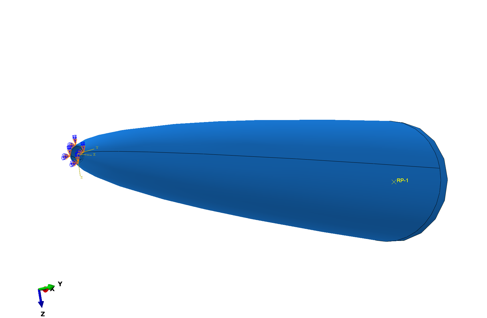
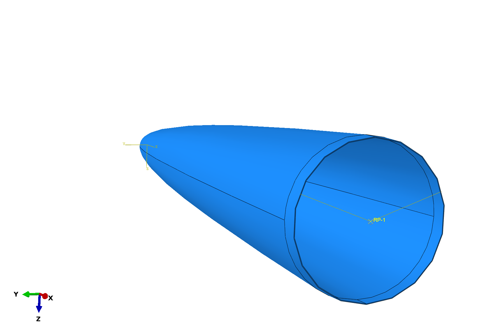
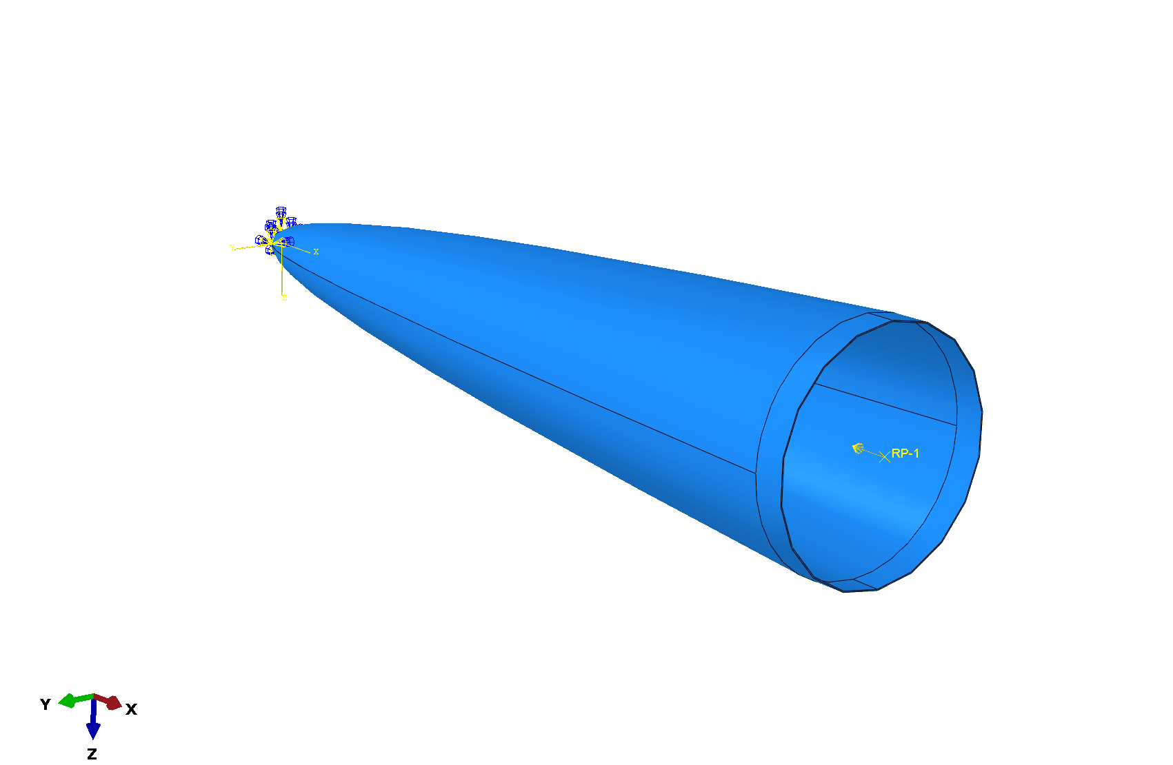
Reference point
- Constraint: Coupling
- Target: RF1 - Center of the base of the nosecone
- Type: Kinematic
- Constrained DoF: U1, U2, U3, UR1, UR2, UR3
 Every points of the top surface move with the middle point RF1. This is useful when applying moment or concentrated load.
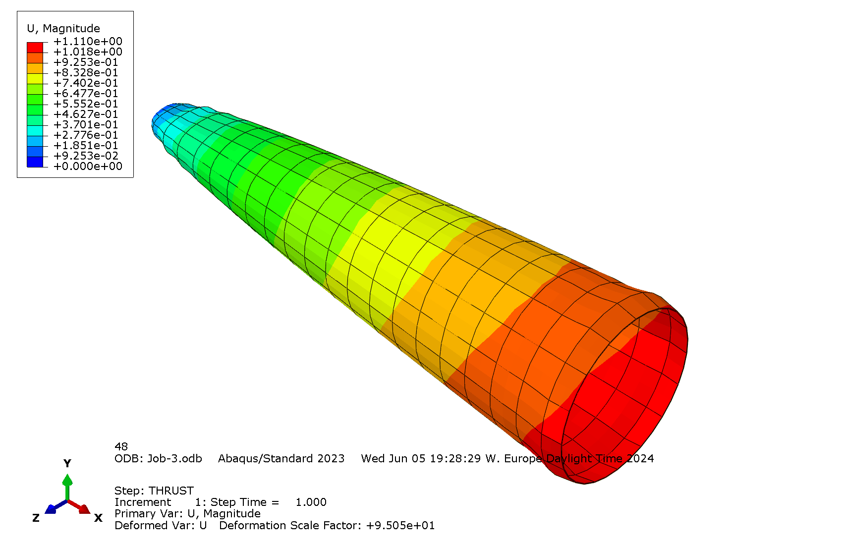
Compression force
- Load: Concentrated force
- Magnitude: CF1= [N]
- Target: RF1
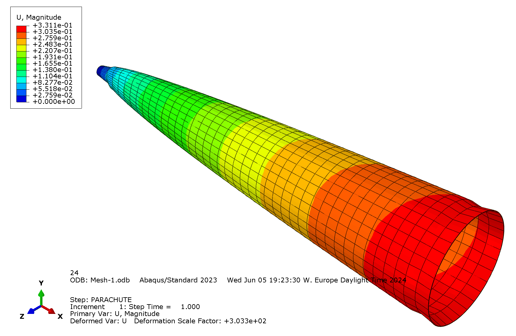
Tensile force

- Load: Concentrated force
- Magnitude: CF1= [N]
- Target: RF1
Bending moment

- Load: Moment
- Magnitude: CM2= [Nmm]
- Target: RF1
¶ Mesh
- Element library: Standard
- Element family: 3D stress
- Element shape: Hex
- Geometric order: Quadratic
Maximum displacement under compression and traction are chosen as convergence criteria
|---|---|
| |
| |
|
| Displacement under compression ; Mesh size = | Displacement under traction ; Mesh size = |
|---|---|---|---|
|Size [mm]| | | |
Ucomp [mm] ||||
Deltas [%]|/|||
Utrac [mm] ||||
Deltas [%]|/|||
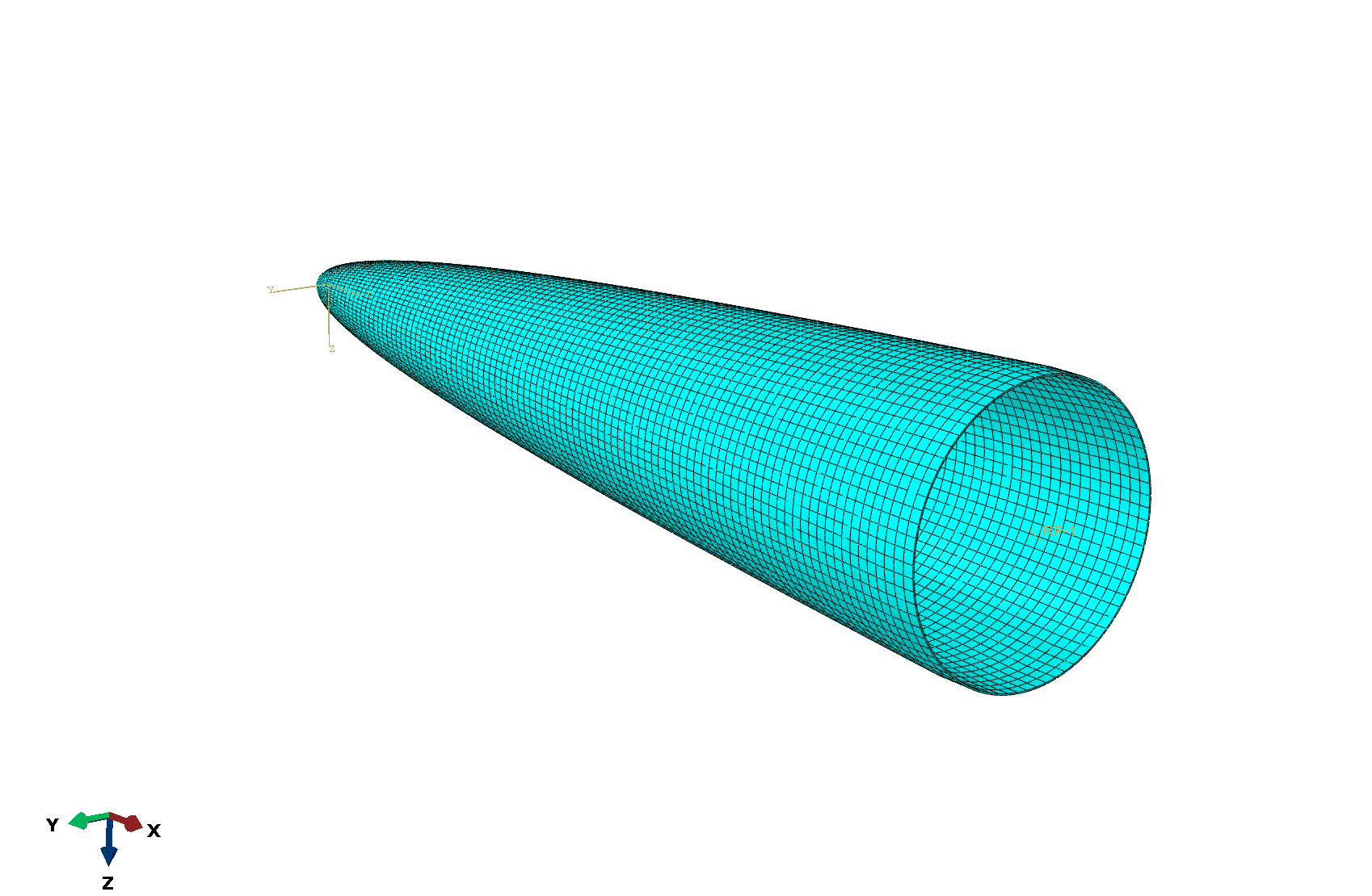
Final mesh size: [mm]
¶ Outputs
Compression
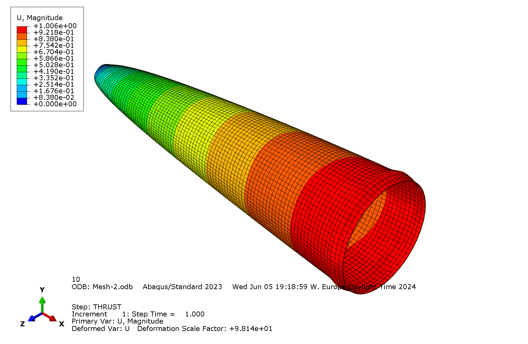
There is no maximum displacement requirement but overall [mm].
Traction
There is no maximum displacement requirement but overall [mm].
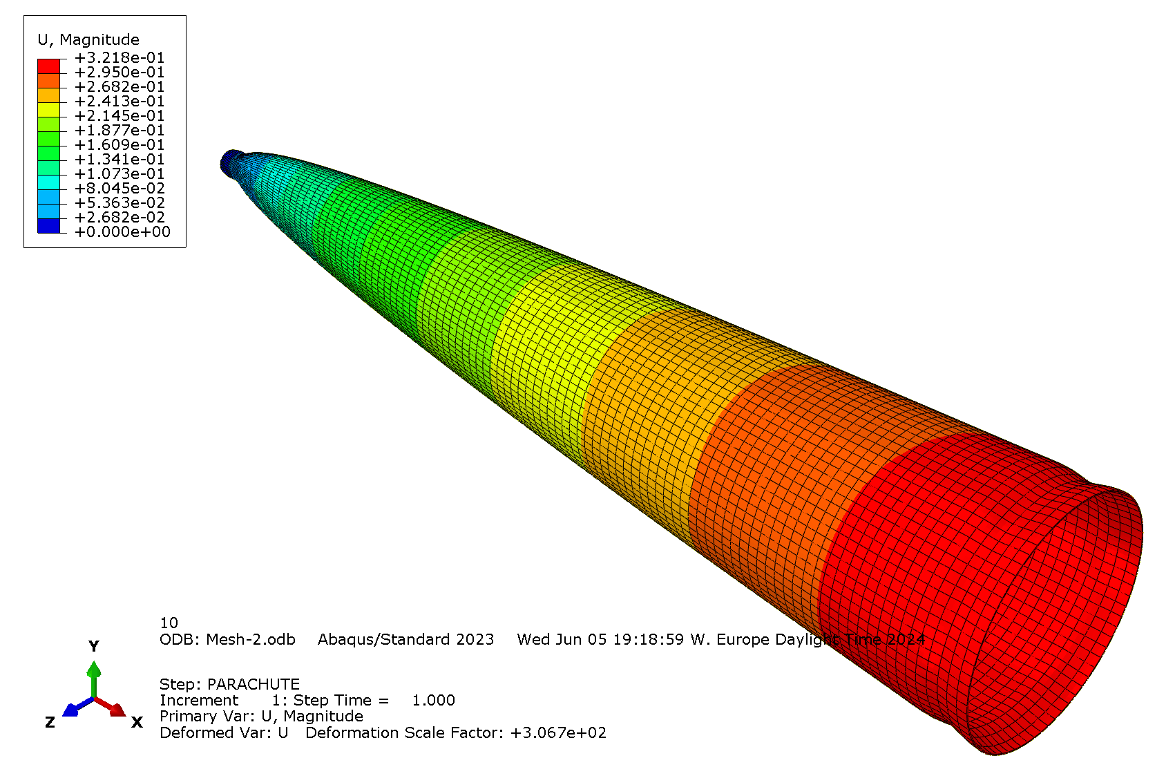
Flexion
Displacement under flexion is not relevant as the boundary conditions is unrealistic. Moreover, the maximum displacement is in the order meters.
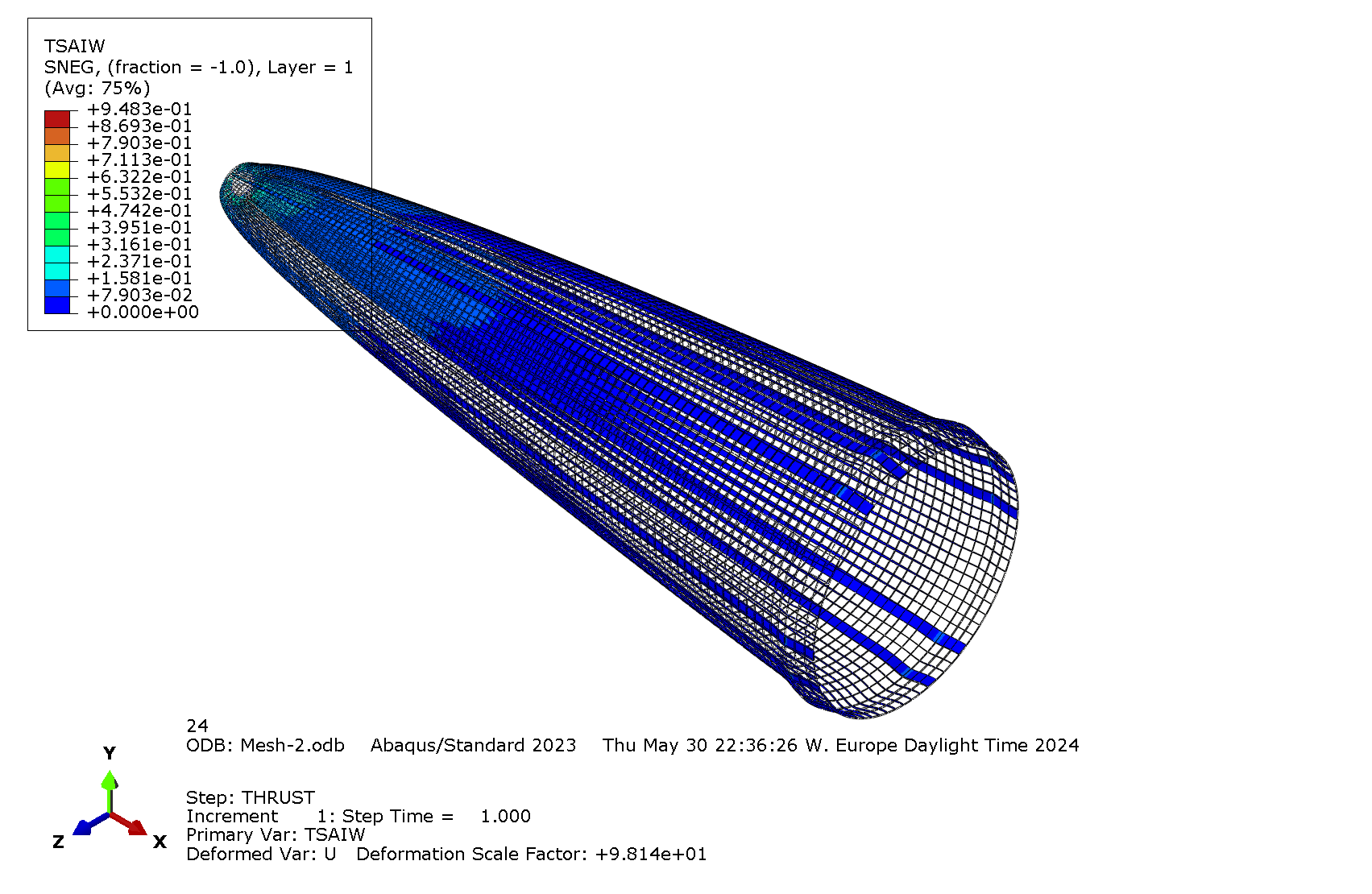
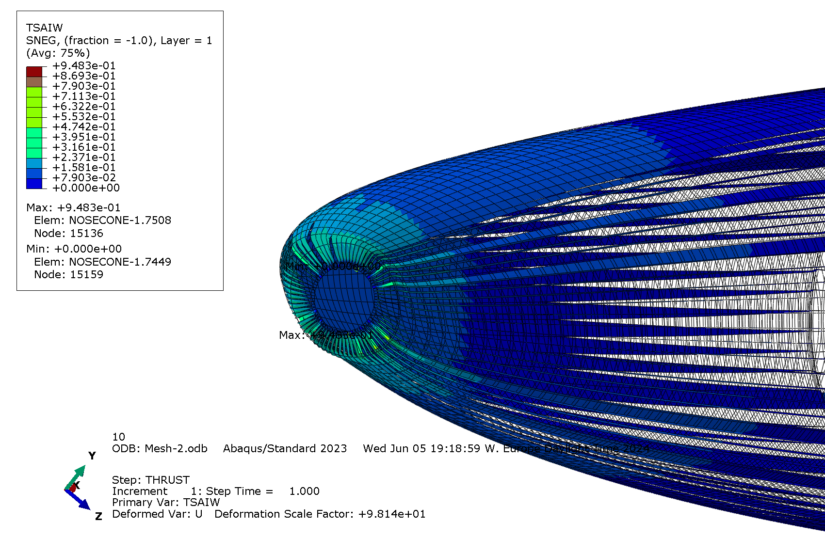
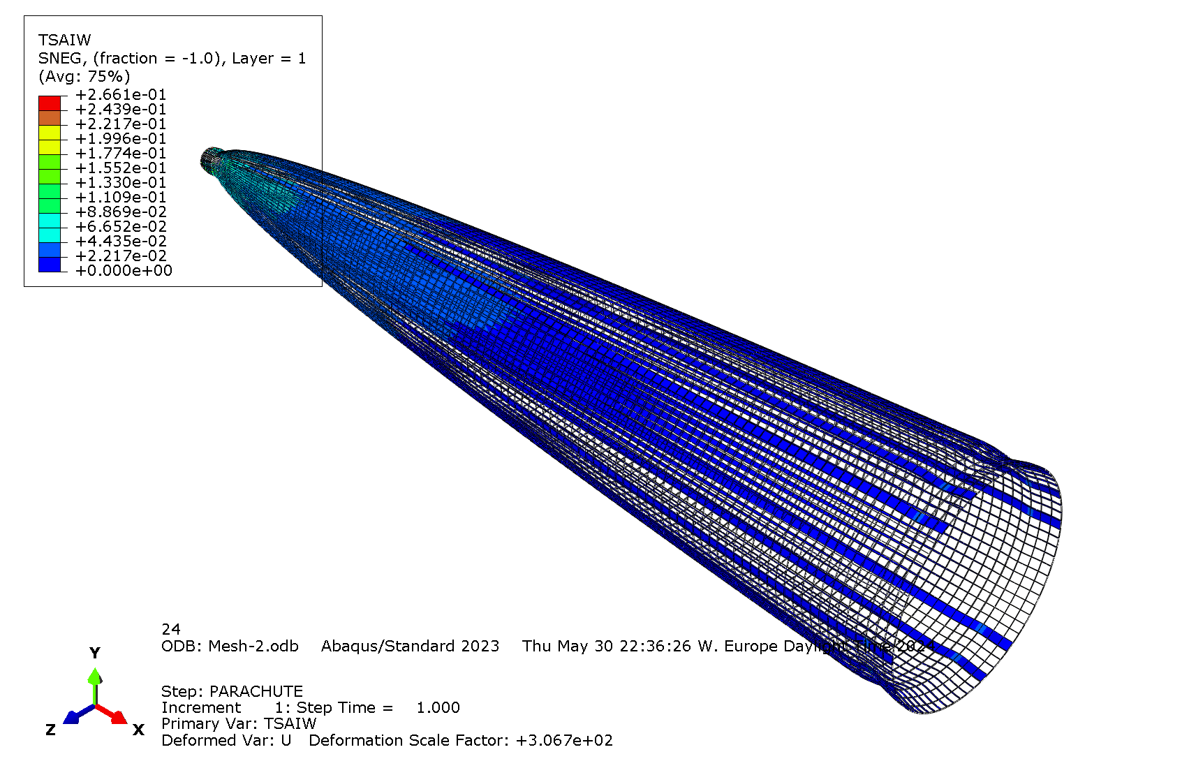
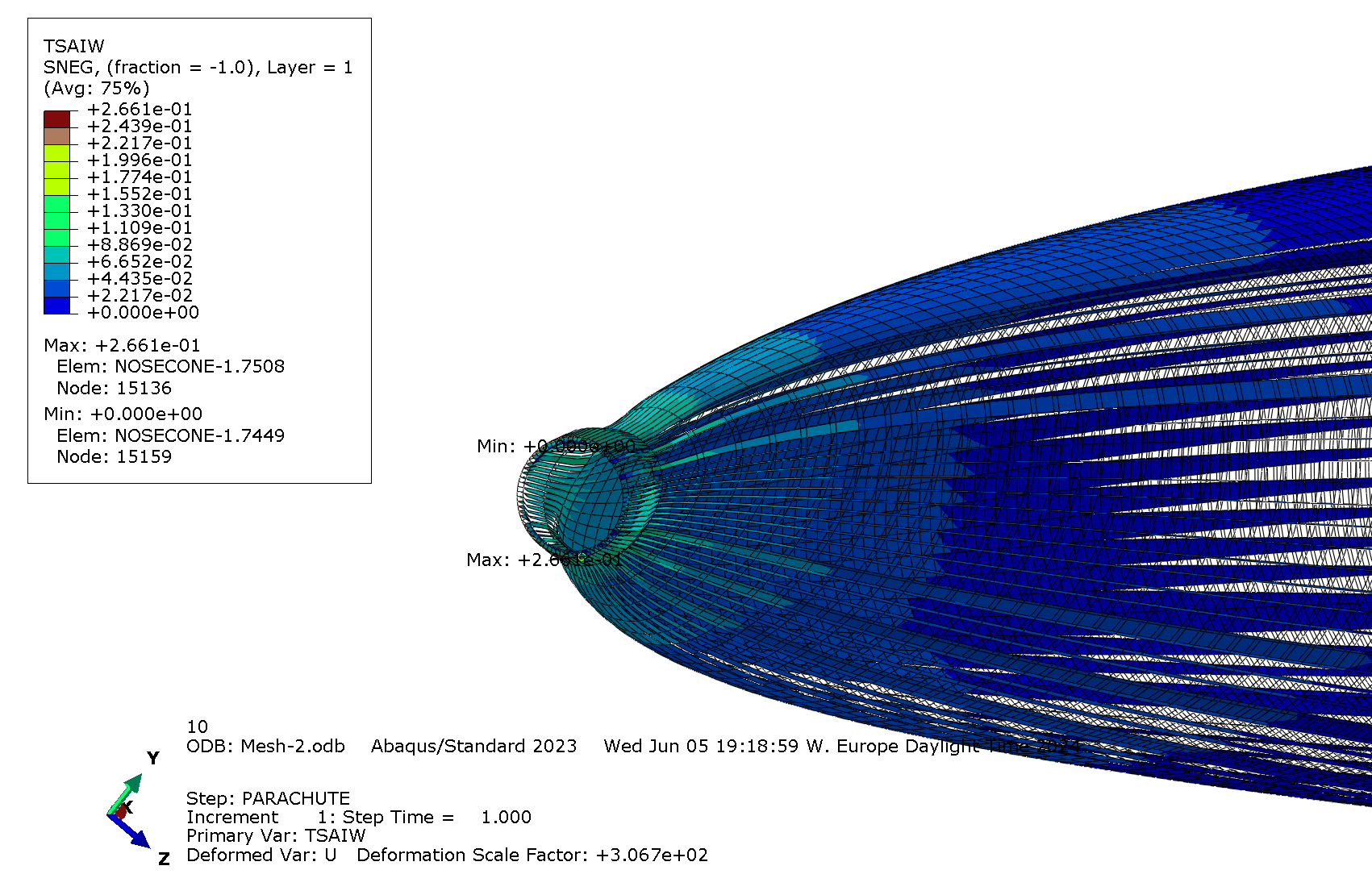
The part resists load if TSAIW
Compression
|---|---|
| |
| |
|
| Tsai-Wu criterion under compression | Tsai-Wu criterion under compression (zoomed at the tip) |
everywhere.
Outputs right at the tip are not relevant. It can be expected from the boundary condition that there will be a load concentration there. Therefore, the maximum value considered is taken below the tip: .
Traction
|---|---|
| |
| |
|
| Tsai-Wu criterion under traction | Tsai-Wu criterion under traction (zoomed at the tip) |
everywhere.
For the same reason as for compression, the maximum value considered is taken below the tip: .
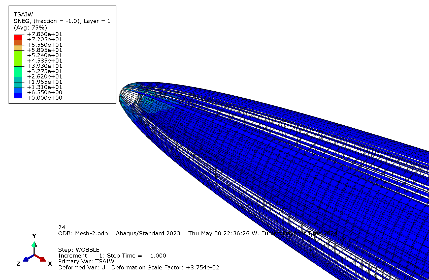
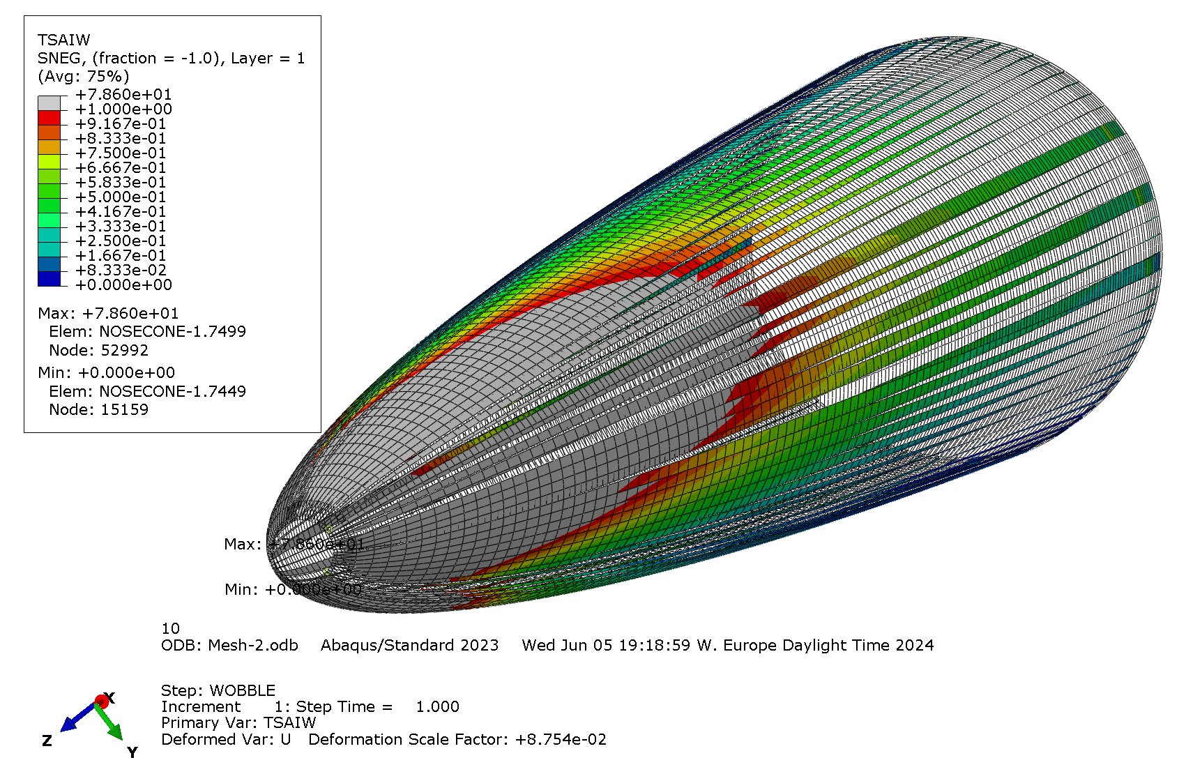
Flexion
|---|---|
| |
| |
|
|Tsai-Wu criterion under flexion | Tsai-Wu criterion under flexion (displaying in grey the failure zones) |
for about of the length from the tip and, for with mirror symmetry .
The load case is unrealistic. The nosecone will never have to bend with the boundary condition on the tip. Apart from that, the rest of the part resits with acceptable margins.
|---|---|---|
| |Minimal |Location of minimal |
|Compression|| Around the tip |
|Traction|| Around the tip |
|Flexion|| / |
¶ Interpretation
¶ Simulation validity
Even though the compression and traction boundary conditions are unrealistic, the results give some insurance on the structural integrity of the nosecone.
-
2024_C_SE_ST_REQ_31
ST Load Case - Axial compression
-
2024_C_SE_ST_NOSECONE_REQ_10
Nosecone load case 1 - Deceleration
The bending case shows large failure regions. However, during the flight, the tip is free to move when a moment is applied. Even if there is some lagging response between the tip and the base, the nosecone shall never undergo a clamping condition. Thus, the tip should not bear such a high moment.
- 2024_C_SE_ST_REQ_34
ST Load Case - Bending moments
The different simulations are performed for ideal load cases (i.e. the load are applied parallel or perpendicular to the main axis). In order to better assess the structural integrity, some additional simulations can be performed:
- buckling analysis
- load cases with diffrent orientations and point of applications
- fluid pressure resistance analysis (have to wait for CFD data)
It is especially difficult to model composite lay-up for curved geometry. The meshing software, cannot display the exact stacking plot. So, the junction of two adjacents plies (if there are) is completely unknown. In fact, such a junction (e.g. two 45° plies) may generates failure prone lines but it is ignored. The simulation assumes a defect free laminate. Therefore, having high might mitigate for manufacturing defects.
Lastly, the nosecone is designed to host a payload and to be attached to the Recovery-Bay. Assembly simulations are then relevant. It is worth noting that the structural integrity should be improved in that case as the other parts strengthen the nosecone.
¶ Conculsions
The chosen lay-up: [0, 45, 0]SO displays satisfying results for the given requirements but additional analysis might be needed.