¶ Objective
This document aims to present the rationale for the selection of the tooling used to manufacture the CFRP nosecone.
¶ Relevant knowledge needed
¶ Tooling
One of the most important parameter for tooling selection is the coefficient of thermal expansion (CTE). The tool's coefficient should match that of the composite.
Types of Tooling
| Type | Characteristics |
|---|---|
| Male mould | - Most commonly used for aircraft parts because of its low cost - Lowest layup cost - Small radius producibilibility 1.27 mm - Baseline (non-aerodynamic surfaces) - Surface control one side only - Localized control of vacuum bag surface |
| Female mould | - Limited use in contour applications because of bend radius - Highest layup cost - Radius producibility 6.35 mm - Localised control of vacuum bag surface - Surface control one side only |
Ideal tooling characteristics for composite:
- CTE characteristics compatible with part to be produced
- Able to withstand severe temperature and pressure conditions without deterioration
- Dimensional stability
- Low cost
- Durable
- Reproduce pattern with high dimensional accuracy
- Retain mechanical properties at high temperature
Tooling expansion factor
Tooling scaling factor
¶ Autoclave
IMAGE AUTOCLAVE SYSTEMS p.160
BRIEF DESCRIPTION
| Potential uses | Pro  |
Con  |
|---|---|---|
| Large components | Low cost | Low production rates |
| Low volume production | Internal heating possible | High labor cost due to ancillary material layup |
| Honeycomb sandwich assemblies | Undercut feasible | Loose dimensional control of bag surface |
| Cocured parts | Vertical walls attainable | Low molding pressure, relative to matched dies require more generous radii |
| Parts having vertical walls | Versatility, particularly with large components | Curing temperatures limited by ancillary materials unless interally heated tools are used with insulation installed between bag and layup |
| Bonding | Complex cocured parts attainable | More process variables involved than with matched dies |
| Thermal expansion can be made to match part | Bag failure usually causes part to be scrapped |
Criteria to be complied with:
Low mass tools
Promotion of efficient heat transfer
Designing the tool to allow as much circulation of heated gas around and throughout the tool as possible
¶ Tooling options
This type of tooling requires a mould that has the same shape as the part. The prepregs are layed directly onto the mould and then vacuum bagged to maintain the shape. The layup is cured in an autoclave.
¶ Conventional tooling
Positive mould made of aluminium (https://www.reddit.com/r/rocketry/comments/bosj7h/carbon_fiber_nose_cone_from_male_mold/)
There are several tooling materials such as aluminium, steel and ceramic that can be used to produce a nosecone. However, the team lacks experience and means to work with the last two options, which leaves aluminum as the potential tooling candidate.
| Pro |
Con |
|---|---|
| Machineability | Dimensional stability |
| Thermal conductivity (177 W·m⁻¹·K⁻¹) | Becomes soft when heated over 177 °C |
| Pressure from expansion | Easily distorted |
| Low density (2.70 g·cm⁻³) | Incompatible coefficient of thermal expansion (CTE = 23.6 µm·m⁻¹·K⁻¹) |
This type of tool costs a lot of money especially for the nosecone as it needs to be milled from a huge cylinder bulk.
¶ 3D-printed tooling
Printed positive mould (https://www.stratasys.com/en/industries-and-applications/3d-printing-applications/tooling/composite-tooling/)
FDM (Fused Deposition Molding) tooling typically starts with a CAD model, which is then sliced into thin layers. The FDM printer deposits thermoplastic material layer by layer, gradually building up the desired shape. Once the tool is printed, it can be finished and used directly or used to create a composite part.
|---|---|
| Pro | Con |
|  lead time | Strength and Durability |
| cost | Temperature Resistance |
| Simplifies tool design and fabrication with increased functionality | Dimensional Accuracy |
| Permits trouble-free design changes and iteration | |
| Reduces tool mass by >80% (relative to metallic tooling in particular) | |
3D printed tooling has prooven to be very cost-effective and reliable for laminates cured at low temperature. However, using an autoclave requires a tooling made of high temperature resistant filaments and designed to withstand hydrostatic pressure.
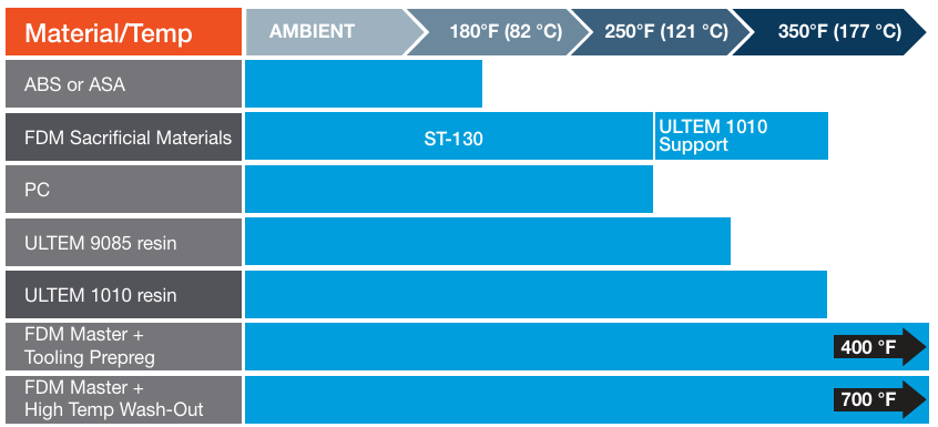
Approximate cure temperature capability for FDM tooling materials
¶ CFRP tooling
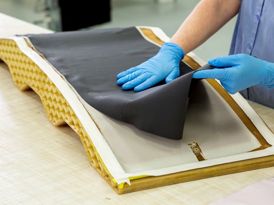
This method option is useful only if the 3D printed tooling is not possible for temperature reason.
A mold is first created using a master pattern, which can be made from various materials such as wood, foam, or even 3D-printed plastic. The master pattern is shaped to the desired form of the final tooling.Once the master pattern is ready, it is often coated or treated to achieve a smooth surface finish and to ensure that the mold release agent will work effectively. Layers of carbon fiber fabric or pre-impregnated carbon fiber sheets (prepreg) are then laid up onto the prepared master pattern. The carbon fiber layers are typically combined with a resin matrix, such as epoxy, to form the CFRP composite. After the layup is complete, the mold is often placed in a vacuum bag to remove any air bubbles and ensure proper consolidation of the composite layers. The mold is then cured at an elevated temperature to harden the resin matrix and bond the carbon fiber layers together. Curing times and temperatures vary depending on the specific resin system used and the size and complexity of the tooling.Once cured, the CFRP tooling is removed from the mold and may undergo additional finishing processes such as trimming, sanding, or machining to achieve the final dimensions and surface finish required for the application.
| Pro |
Con |
|---|---|
| lead time |
Durability |
| cost |
Limited strength at high temperatures |
| Excellent dimensional stability | Must build master model |
| Good heat-up rate | |
| Lightweight | |
| Very compatible CTE |
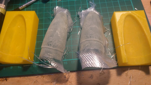
This type of tooling requires a two half-moulds to shape the part. Prepregs are layed on each half-mould while leaving some hanging fabrics. The mould is then closed and the hanging fabrics are layed against each other.
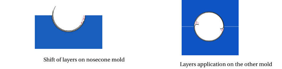
Nosecone lamination using female mould
¶ Epoxy tooling
Epoxy tooling female half-mould
Blocks made of epoxy foam are available in the market. They are CNC machined to get the desired shape.
| Pro |
Con |
|---|---|
| Dimensional stability | Durability |
| Surface finish | Temperature resistance |
| Time consuming machining | |
| Expensive | |
| Requires bulky design for integrity |
Needs to be machined by professional workshop as the team does not have the necessary equipment. Price scales drastically with part size.
¶ 3D-printed tooling
Same characteristics as the male version
FDM tooling female moulds (https://concretedog.blogspot.com/2020/04/fibreglass-rocket-nosecones-using-3d.html)
¶ Narrowing the tooling options
¶ Requirements and design criteria
Requirements are yet to be been formulated. In the meantime, the tooling type is selected through industrial considerations, adapted to the team's expectations.
Rating of tooling properties (factor: 1 -lowest; 5 -highest)
| Industry | ERT | Justification | |
|---|---|---|---|
| Tooling properties | Factor | ||
| Dimensional accuracy | 5 | 4 | It is difficult to control the accuracy of the nose's geometry once the part is produced |
| Dimensional stability | 5 | 5 | |
| Durability | 5 | 2 | Only two nosecones will be produced |
| Thermal mass | 4 | 1 | Curing temperature will be closely monitored |
| Surface finish | 3 | 2 | The surface will be post-processed |
| Ease of reproducibility | 3 | 3 | |
| Temperature uniformity | 3 | 3 | |
| Material cost | 3 | 5 | The team cannot afford to buy toolings that will be used at most twice |
| Ease of tool fabrication | 3 | 5 | The team should be able to produce new tooling in case of failure |
| Ease of repair | 3 | 2 | Tooling will be used at most twice |
| Tool weight | 3 | 3 | |
| Ease of inspection | 2 | 2 | |
| Resistance to handling damage | 2 | 2 | |
| Ease of thermocouple implantation | 1 | 1 | |
| Release agent compatibility | 1 | 1 | |
| Sealant compatibility | 1 | 1 |
¶ Male 3D-printed mould
¶ Material selection
The material selection is constrained by the available supplier and 3D-printer
The team have access to the 3D-printing facilities offered by the SPOT. Therefore, it is easier to comply with the filaments they propose. As the prepregs used need to be cured at high temperature, temperature resistant filaments have to be used for the mould.
High temperature filaments
| Filament | Material | Temperature resistance [°C] | Other |
|---|---|---|---|
| colorFabb_HT | PETG co-polyester | 100 | Heat deflection temperature: [°C] at [MPa] |
| Polymaker PC-Max ™ | Polycarbonate | 113 | / |
| Protopasta Carbon Fiber PETG | PETG-CF | / | / |
¶ Tests
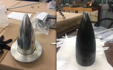
Only the tip of the nosecone was printed for the tests. This reduced printing time and cut costs.
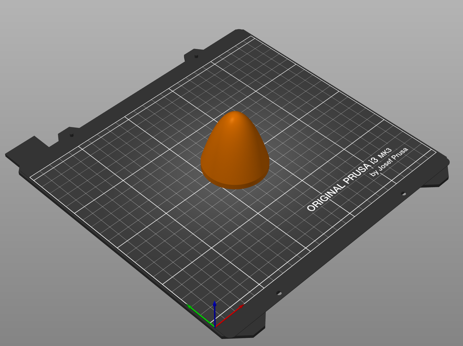
Hollow tip
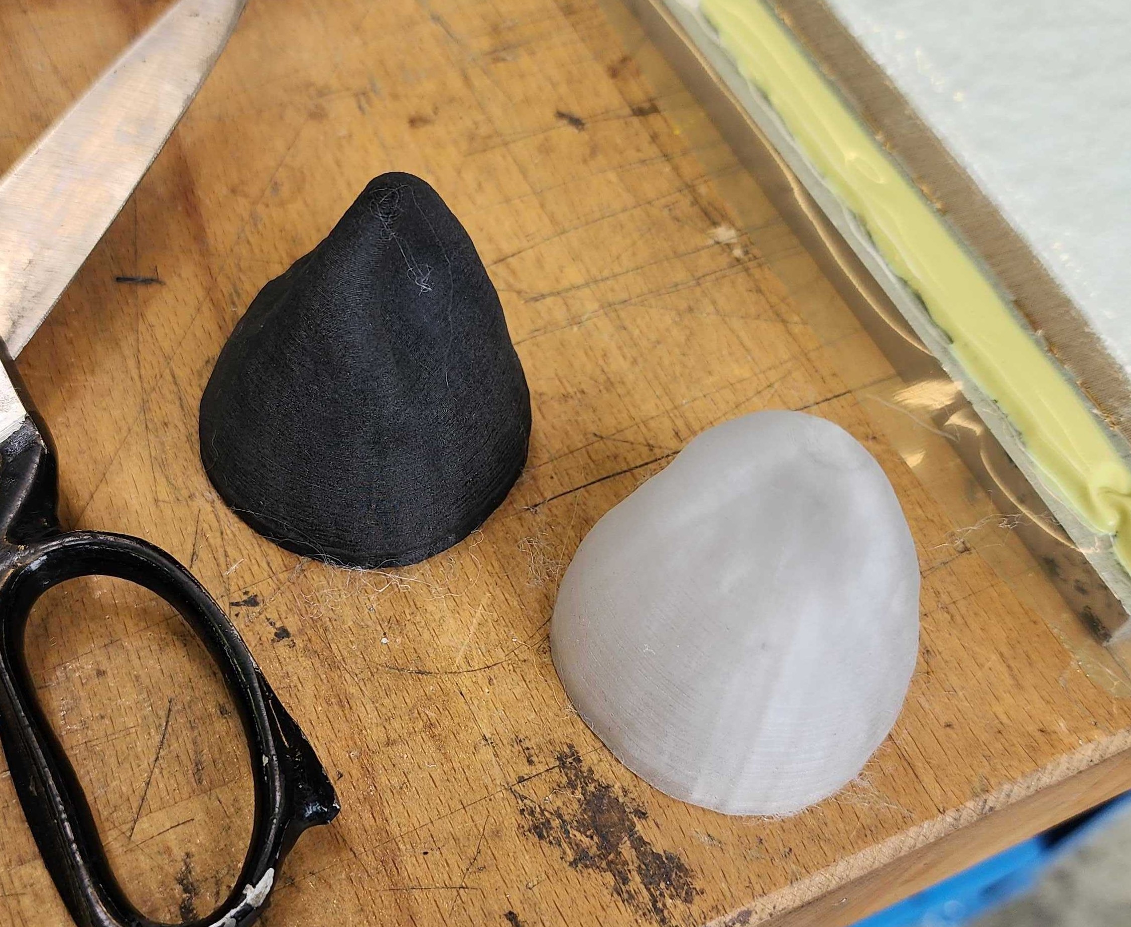
A very preliminary test was carried out to see if the HT and PC could withstand high temperatures. First, they were put as printed in a domestic oven for [min] at [°C]. Second, they were heated for [min] at [°C]. A visual check was done after each step to see if there were permanent warping. The samples remained intact after at the end of the test. However, it is worth noting that the oven does not have a real-time feedback for the temperature inside. The temperature can just be controlled with a thermostat.
Once the temperature resistance had been qualified, the pressure resistance were verified. The samples were put in a vacuum bag in order to be vacuumed. Then, they were put in an autoclave. Inside, they were heated to [°C] in [min], stayed there for another [min] while pressurising in the meantime the autoclave to [bar]. After that, they were heated to [°C] in [min] and, stayed there for another [min]. The autoclave was cooled down to [°C] in [min] and, depressurised at the end.
The figure shows that there are some permanent deformations. The pressure resistance test failed. This can be explained by:
- Experimental factor: the vacuum bag was not well inserted in the hollow part of each sample, resulting in a pressure gradient there when the autoclave were pressurised and, causing a deformation.
- Ignorance of filament properties: the heat deflection temperature of HT under load was known much later. In fact, the temperature resistance decreases when a load is applied due to creep.
Moreover, it was reported that the visible infill at the base was distorted. It is likely that the combined effect of pressure and temperature softened the infill.
In order to prevent the vacuum bag issue, the tip was truncated, leaving a through-hole. Hence, a mould can be squeezed between two vacuum bags, one wrapping the inside and the other one wrapping the outside.
Due to the lack of time, only HT mould was printed. It is easier and faster to print compared to PC for the same geometry.
As the pressure test failed, it was decided to scrap the usage of an autoclave and simply use a laboratory oven while vacuuming. Moreover, the heating temperature was reduced to [°C] to reduce the probability of softening occurence.
By vacuuming, the mould was put under atmospheric pressure. Then, it was put in an oven at [°C] for [min].
No permanent deformation or damage were reported at the end of the test.
The surface of the mould has to be treated before laying-up prepregs on it. The preliminary steps:
- Sanding: a mould's surface has to be as smooth as possible to facilitate demoulding. Additionally, the roughness of the part is the same as that of the mould. Generally, the surface of 3D-printed object is very rough, the deposited layers are visible.
- Primer: this maximises surface sealing and eliminates substrate porosity. It also gives a glossy surface to the mould.
- Release: gives high slip, high gloss surface finish for composite parts.
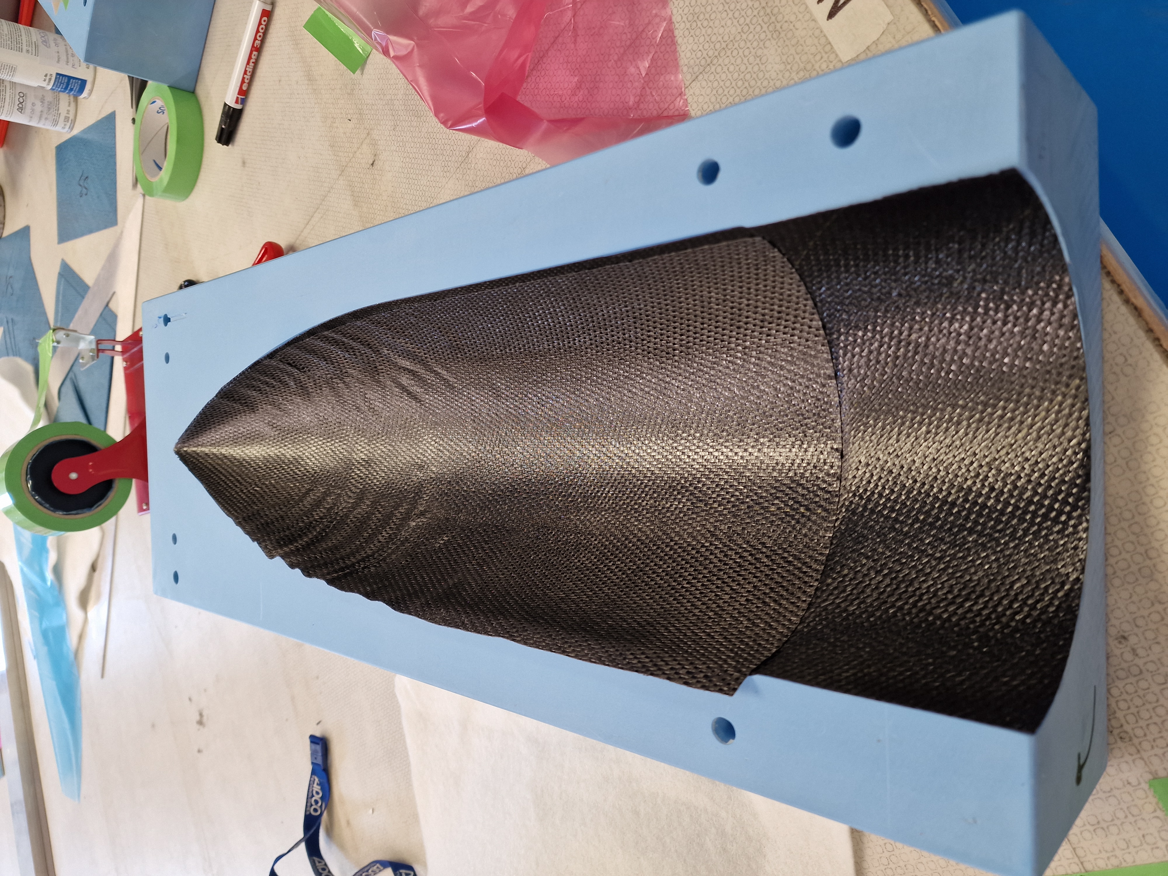
Once it was done, the prepregs were layed ontop of the mould. As the objective of the test is to qualify a 3D-printed male mould, the manufacturing of the CFRP part to be moulded was a bit neglected. Four layers of uni-directionnal carbon prepregs oriented at 0° were applied and then some consumables were applied. The procedure afterward was basically the same as for the previous test.
The test was a success, the surface of the mould remained unscattered and the CFRP part had the desired shape. Some additional sanding could have been done, the inner surface of the part was still a bit rough making it difficult to demould. Moreover, no disturbing wrinklings were reported.
Parameters
- Mould design
- Printing settings
- Temperature
- Pressure
Results
| Test | Design | Printing settings | Temperature [°C] | Pressure [bar] | Result |
|---|---|---|---|---|---|
| Domestic oven | Tip ; [mm] thick | perimeter ; infill | / | |
|
| Autoclave | Tip ; [mm] thick | perimeter ; infill | |
||
| Oven + Vacuum | Truncated tip ; [mm] thick | Full perimeter ; No infill | |
||
| Prepregs laying-up | Truncated tip ; [mm] thick | Full perimeter ; No infill | |
In the end, the use of an autoclave is unecessary as the laminate is very thin. Doing so allows also to cut the manufacturing cost.
¶ Final choice
Mould type: male 3D-printed
Material: colorFabb_HT
Printer: Prusa XL [mm]
Parameters
- Design: divided in three parts ; [mm] wall thickness
- Printing settings: Full perimeter on walls ; infill where it is needed
- Curing temperature = [°C]
- Pressure [bar]
One of the difficulties in demoulding was that the cylindrical length of the mould matched that of the moulded part. With manufacturing defects, some prepregs were pressed against the mould's edge during curing, blocking the mould from demoulding. In consequence, the mould is designed with additional cylindrical length ( [mm]).
Due to printing volume constraint, the mould has to be divided in at least three parts, requiring some assembly techniques. For the rocket Nordend, the nosecone itself was 3D-printed, implying the same problem. Its parts were glued together. However, the payload inside involved an aluminium frame and, some issues were reported after a drying at [°C]. In fact, the frame expanded along the nosecone axis, exerting a tensile load on the joints of the different parts and, resulting in the end in a complete dissassembly of the nosecone. The lesson learned is that, metallic parts should be avoided to assemble a 3D-printed part which will be put in an oven.
So, the mould's parts are designed in such a way that they can be assembled together with just geometric coupling. This system involves a male part, fitted in a female part such as the coupling system of the rocket Firehorn.
As the parts are 3D-printed, the overhangs shall not exceed 45°. Otherwise, supports are needed.
Scaling factor
- CTEPETG = [m.(m.K)-1]
- CTECFRP = [m.(m.K)-1]
- = [°C]
This value is inputted in the software SolidWorks
Unscaled nosecone mould design
¶ Perpsectives
- Current design
Printing trials are needed to find the good tolerances for the couplings. Only the coupling parts can be printed in order to save material whill still validating the design.
The wall thickness can also be increased if [mm] is too thin. - Tip
A vacuum test is required to validate the tip. It is important to verify if it can bear the atmospheric pressure at high temperature even if the vacuum bag is misplaced. The latter could happen as the tip's entry is narrow. If the test fails, the tip can be truncated, forcing the nosecone to have a non-CFRP tip.