¶ Introduction
¶ Purpose, Objective and Scope
This document aims to provide detailed assembly instructions and outline the manufacturing methods used for the nosecone.
It will allow the structure team members to trace the production history of the part and use it as a reference for future composite components.
It focuses specifically on the techniques used for the manufacturing of this nosecone and his history, rather than generals composite processing methods.
Layer configurations and other technical parameters are not covered in this document.
You will notice that the nosecone has no tip. For ease of layup, we decided to manufacture this part separately using PET_CF 3D printing.
This document does not cover the interface with the tip nor its manufacturing process.
¶ Definitions and Abbreviations
- ABV : Abbreviations
- PP : PealPLy
- MR : Molde release
- Gum-Gum : Tacky-Tape
¶ Applicable and Reference Documents
For more general information on infusion methods, please refer to the attached MAP_infusion document.
Additional documents used for the nosecone are listed below:
¶ Parts List
| Description | Qty |
|---|---|
| MDF Mold | 1 |
| Semi-Nosecone | 2 |
¶ Mold Preparation
¶ Tools and Consumables
| Tools | Quantity |
|---|---|
| Dowel pins | Several |
| Laser wood cut | 1 |
| CNC machine | 1 |
| Band saw | 1 |
| Drill | 1 |
| Sandpaper | Several sheets |
| Fusion software | 1 (used for design) |
| Hammer | 1 |
| Consumable | Quantity |
|---|---|
| MDF board (19 mm) (400 * 1000m) | 4 |
| MDF board (19 mm) (460 * 1000m) | 1 |
| MDF board (10 mm) (400 * 1000m) | 4 |
| MDF board (22 mm) (200 * 1000m) | 1 |
| Wood glue | 1 pot |
¶ Participants
The three people involved in the creation of this mold are:
- Emma Gerart
- Thomas Sancenot
- Gabriel Mollet
If you need help, don't hesitate to contact the skill coaches. Stephane, Mark, and Willow were very helpful in creating this mold.
¶ Manufacturing History
This mold was created in 3 iterations before succes. The first one contained too much residual stress in the MDF because wall to thick and to much too much material to remove, and the second one lacked precision.
To avoid repeating these errors, please consider all the comments we have to offer.
To generate an effective G-code, the following factors were taken into account:
- Reinforcing and widening the edges to prevent breakage due to vibrations or glue shrinkage.
- Using laser cutting to mark the different layers of the raw material, then cutting them with a band saw.
- Creating cross marks on the MDF boards to drill precise holes and insert dowel pins between each layer.
- Varying the placement of the dowel pins to improve alignment and stability.
- Gluing the layers quickly to avoid any misalignment.
- Setting the G-code zero point on the top of Mold, rather than at the base.
- Using a pattern to ensure that the CNC tool can access all required areas.
¶ Procedure
-
We pre-marked each layer using laser cutting to give each one a distinct shape and to add cross marks that help align the dowel pins.
-
The layers were then cut using a band saw and drilled with holes matching the dowel pin diameter.
Important: Make sure the laser marking is wide enough — we used 8 mm in our case.
-
We placed a 19 mm thick MDF board (460 × 1000 mm) as the base, and alternated between 10 mm and 19 mm MDF boards (400 × 1000 mm) up to the top, inserting pins between each layer. (A hammer may be required to insert the pins securely.)
-
The desired mold shape and the raw block made of the 9 MDF layers were imported into Fusion.
-
After importing the CNC skill library, we applied a parallel toolpath, reducing machining time from 13 hours to just 1.5 hours for the next molds.
-
Once the G-code was imported into the CNC, the mold had to be carefully positioned by screwing down the larger base plate, then launching the program.
-
The final 22 mm MDF layer was machined separately and then glued to the mold.
-
After obtaining the mold, the inner surface must be sanded using a sanding block or a 3D-printed tool.
-
Don’t forget to sand and round off the mold edges to prevent puncturing the vacuum bag during infusion.
-
Next comes the heating and resin-coating of the mold, which can take one to two days.
-
After sanding it again, the mold must be covered with Teflon tape and then coated with a release agent.
-
We added slippery tape to the end surfaces of the nosecone to facilitate demolding.
The nosecone mold has on the right side an additional 22 mm MDF plate offset a few millimeters inwards. Thus, during the gluing of the 2 pieces, we will have a perfect fit between the 2 identical parts as follows:
¶ Post-Mitigation
After a night of rest following the CNC machining, we noticed that some splinters and small pieces of wood had come off.
This was due to internal stress in the MDF and the machining process, which weakened the joints between the MDF boards.
To solve this, we applied polyester filler, then re-sanded the surface before applying the resin.
Be careful when using the filler, as it dries very quickly and requires gloves and a mask for safe handling.
¶ Carbon Infusion Drapping
¶ Participant
If you have question or you d ont understand the steps of this procedure, ask
- Gabriel Mollet
If you need more help, don't hesitate to contact the LPac coach: Gavin.
Don't forget to send him a message first
¶ Tools and Consumable
| Material Name | Swiss Composite Reference Number |
|---|---|
| Isotacker white spray adhesive | 4060.0500 |
| Aerofix blue spray adhesive | 318.0500 |
| Sicomin epoxy infusion resin | 1710.2153 |
| Diadrin | 390.2205 |
| Connector valve | 77007.0010 |
| Tubes | 77008.0010 |
| Peel ply | 222.0100 |
| Carbon twill 160 g/m² | 190.0442 |
| Mesh grid with porous TVT | 180.0685 ( a verifier) |
| Ventilation Tapes | 390.5210 |
| Bleeder | 923.0150 |
| Vacuum bag | 170.0240 |
| Black gum-gum | 390.1701 |
| Brushes | X |
| Mask | X |
| Gloves | X |
This list should be checked meticulously with Gavin. You'll have also to check if there is any rest of last years manufacturing
¶ Manufacturing History
Each step required time, but we consistently achieved good results.
It's important to plan ahead and stay well organized — some stages are unexpectedly long and can catch you off guard.
¶ Procedure
The layup method was mostly consistent, with only a few minor adjustments:
-
Apply white spray adhesive (spray from a distance and wait 1 minute).
-
Place the first carbon ply. If there are too many tensions or poor adhesion, remove and reapply until the surface is completely smooth.
(Repeat this process for a total of 4 layers) -
Cover with Peel Ply (blue spray adhesive).
For this step, cut 3 pieces of Peel Ply:- One for the left side, extending beyond the midpoint.
- One for the right side, overlapping the first layer at the center of the nosecone.
- One small piece only for the overhang, which must not be glued.
This ensures that the Peel Ply can shift with the vacuum bag, avoiding mechanical blocking that could damage the carbon layers.
-
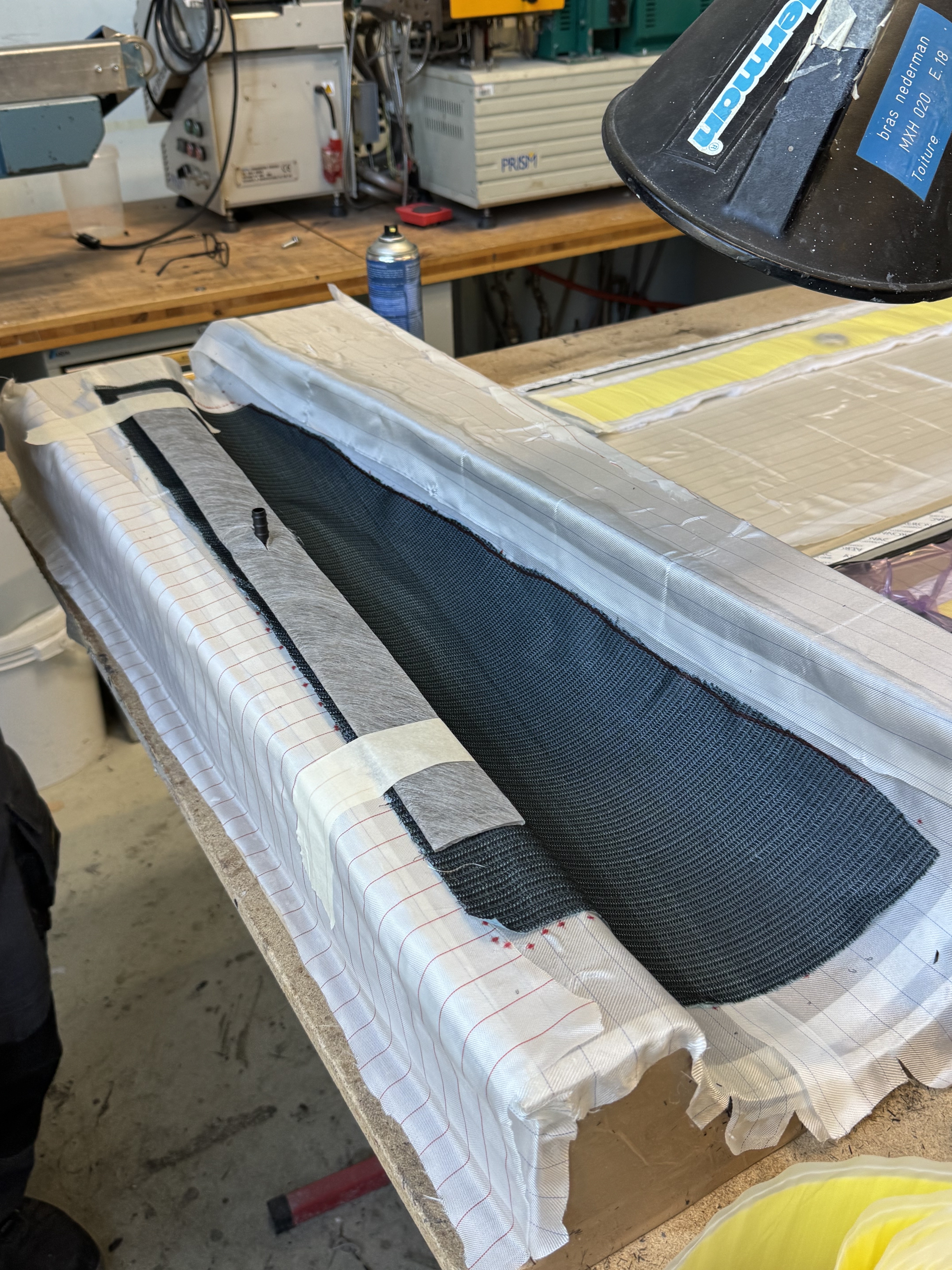
Cover the left side to the middle (and a bit more) with mesh grid using porous TVT.
-
Add Diadrin (starting 50 mm before and ending 50 mm after the mesh grid).
-
Install the connector on the diadrin.
-
Place the vacuum bag over the baseplate:
- First, seal the corners using gum gum.
- Then seal the center of each segment.
- “Ears” must be formed at the corners of the part to ensure flexibility.
-
Perform a vacuum test (drop test).
-
Maintain under vacuum for at least 4 hours.
-
Proceed with the resin infusion after after mixing the base and the hardener and degassing it.
-
Let rest for one full day.
-
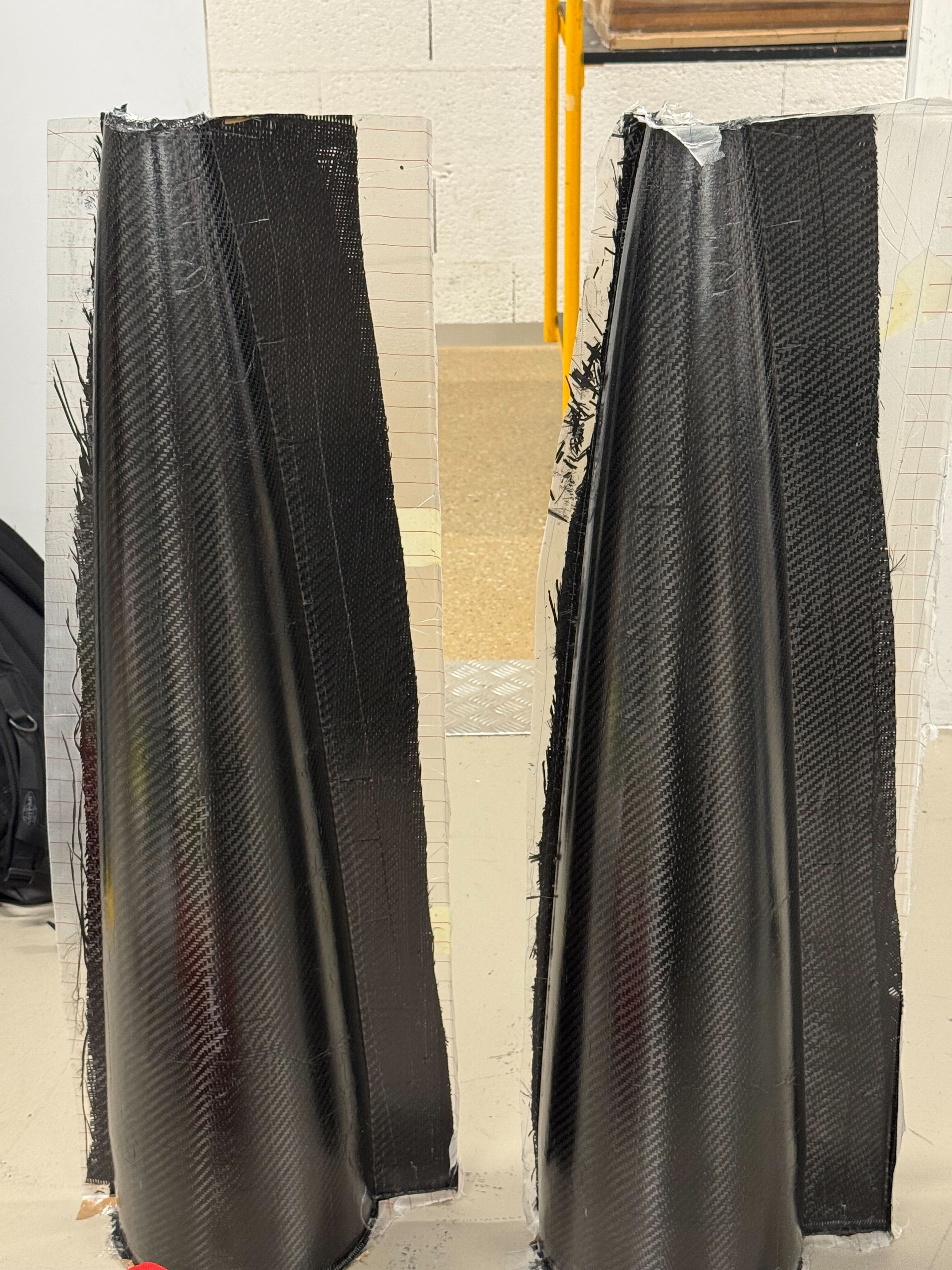
Demolding and post-curing.
¶ Result :
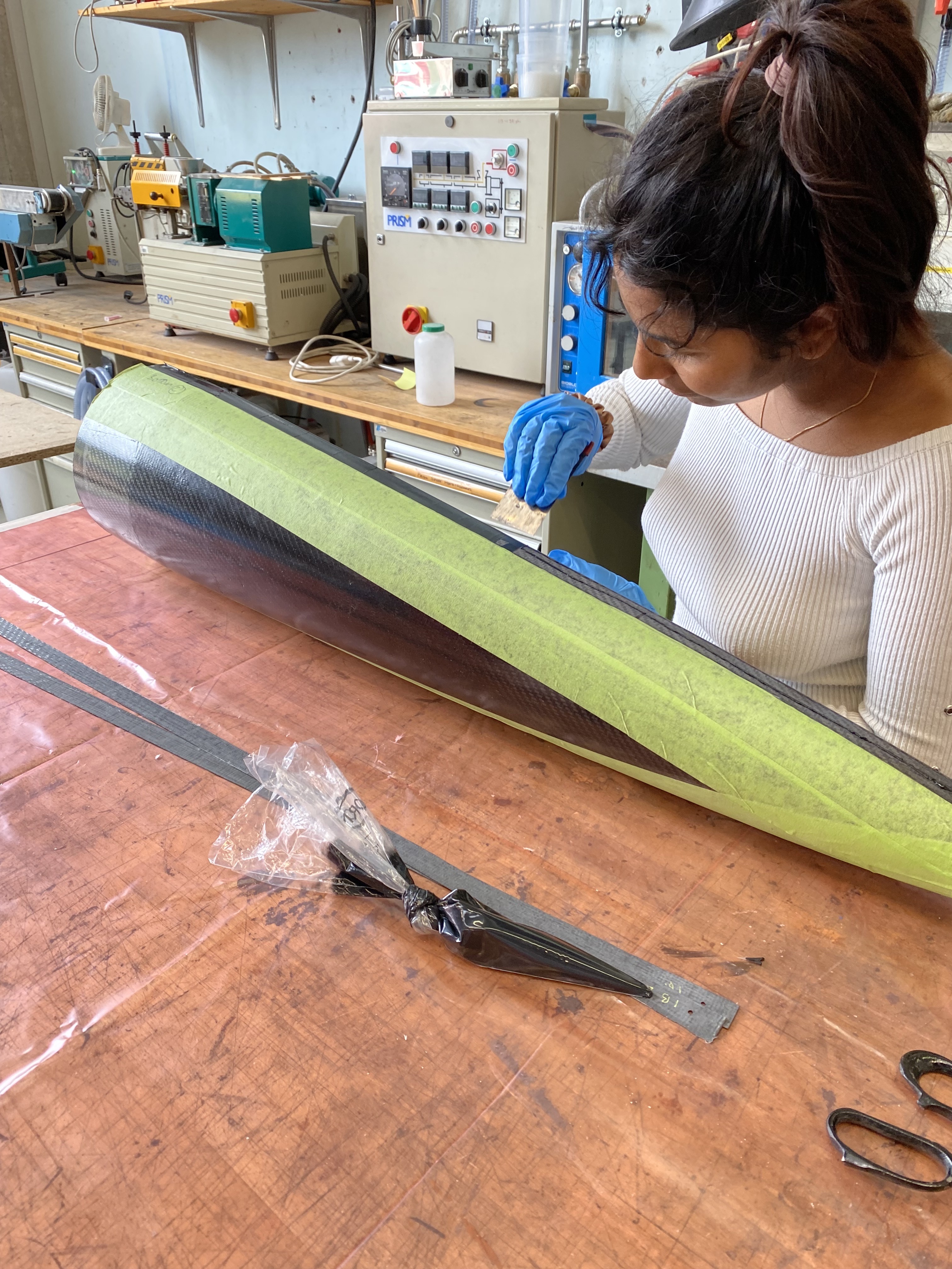
¶ Assembly
- Trimming of excess material
- Application of DP 490 adhesive on the buté
- Assembly
Schema of the assembly of the two identical parts :
- Application of rivets at the ends of the joints to ensure alignment
- Peel ply applied to absorb excess adhesive on the inner and outer junctions
- Placement of mesh grids around the part
- Vacuum bagging and compaction for more than 4 hours
- Removal of the peel ply
¶ Final Result :
¶ General Comments
The mold was a very long and energy-consuming stage because we tried to move too quickly from the start. We didn't ask enough questions to Gavin, and we showed him a CAD model of the mold too late. On top of that, we underestimated the importance of precision when preparing the raw block.
Without all these issues, we could have completed the part in about 3 to 4 weeks.
However, we managed to adapt our methods and improve the process to make it shorter and reduce the risk of failure.
Here is a chart of the time and money spent to have a room from start to finish:
| Operation | Active Time | Passive Time | Number of Operators | Location | Estimated Cost (CHF) |
|---|---|---|---|---|---|
| Cutting and gluing boards | 3h | 1 day | 2 | Skill | 90 CHF |
| G-code and CNC machining | 2h + 4h | 6h | 1 | Skill | - |
| Sanding | 2h | 1 day | 1 | Skill | - |
| Heating, resin coating, Teflon taping | 2h | 1 day | 1 | LPAC | 14 CHF |
| Infusion preparation x2 | 1 day | 1 day | 2 | LPAC | 115 CHF |
| Infusion x2 | 30 min | 1 day | 1 | LPAC | 25 CHF |
| Demolding x2 | 30 min | 30 min | 1 | LPAC | - |
| Post-curing x2 | 30 min | 15h | 1 | ENAC oven | - |
We therefore have around 4 days of preparation, and typically between 3 to 4 days for infusion, resulting in a total of about 12 days to produce two semi-nosecones in the best-case scenario.
However, since machines and coaches are not always available, a more realistic estimate is 3 to 4 weeks,with a total cost of approximately 400 CHF.