¶ Introduction
¶ Purpose, Objective and Scope
This document aims to describe the detailed manufacturing procedure of FIREHORN's CFRP tube.
It is addressed to the team members of C-ST and serves as a reference for the future CFRP tubes.
The document will only cover the laminating part of the procedure. It will not describe the post-processing of the tube.
¶ Definitions and Abbreviations
Legends for highlighted text:
Function
Warning / Things to be careful of
Risks
Tips and Indications
Methods
- C: Competition
- CFRP: Carbon Fibres Reinforced Polymers
- MS: Makerspace
- Prepreg: Pre-impregnated fibres
- ST: Structure team
- UD: Uni-directional
¶ Applicable and Reference Documents
- Mould-Sealer: XTEND® UMS Mold Sealer
- Mould-Release: XTEND® ACR-HS External Mold Release
- UD: HexPly® EH25
- Woven: HexPly® F593
- Photos and videos from the 2024 session
¶ Parts List
| Description | Part Ref | Qty |
|---|---|---|
| CFRP Tube | TX | 1 |
¶ Pre-Operations Checklist
¶ Participants
Number:
¶ On-site
| Check | Responsible for: | Name |
|---|---|---|
| COO | (x1) | |
| Cutter prepregs | (x2) | |
| Cutter consumables | (x2) | |
| Compactage/drappage | (x4) |
¶ Materials
¶ Makerspace / DLL
| Check | Item | Qty |
|---|---|---|
| Mould sealer (chemicals rack MS) | 1 | |
| Mould release (DLL) | 1 | |
| Bubble wrap (OBI) | \ | |
| Kevlar cord (malette RE DLL) | ~1m | |
| Mandrel | 1 | |
| Jig | 1 | |
| Thin cord 6m | 1 | |
| Chemical vapours mask | 2 | |
| Allen key set | 1 | |
| wide bodywork tape | 1 | |
| Pen/markers | 4 | |
| Alcohol | 1 | |
| Backup screws set for jig | 1 |
¶ APCO
| Check | Item | Qty |
|---|---|---|
| HexPly®EH25/34 %/UD136/HTA-12K | \ | |
| Non-porous TVT / Peel-ply | \ | |
| Non-perforated film release | \ | |
| Breather | \ | |
| Grid breather | \ | |
| Vacuum bag | \ | |
| Elastomer | \ | |
| Nitrile gloves | \ | |
| Measuring tools | \ | |
| weights | \ | |
| Freeze spay | \ | |
| PTFE tape | \ | |
| Tacky tape | \ | |
| Vacuum connectors | \ |
¶ Technical drawings
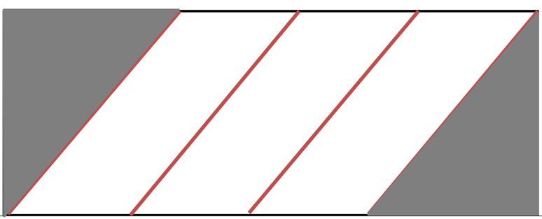
- Solid lines indicate the prepreg roll
- Dashed lines are the cutting lines
- Couloured areas indicate the desired cut
- Red arrow indicates the orientation of the roll's fibres
UD prepregs
UD prepregs
.png)
Detailed cutting pattern
¶ Mandrel Preparation (off-site)
Makerspace / DLL
¶ Mandrel
Always wear a chemical vapours mask and nitrile gloves while manupulating the mould sealer and mould release
¶ 1. Wipe-On mould sealer
To seal micro-porosities
- Apply to ambient temperature molds by wiping
with a clean, woven, paper cloth.- Work in patches, applying a smooth, continuous
light film over an area approximately 0.3-0.8m² square, or a size that you can conveniently wipe before it dries. A nice wet coat should be applied, but without runs, puddles, or drips.
¶ 2. Wipe-Off mould sealer
As the sealer starts to flash off (3 seconds to 3
minutes), use a clean, dry paper cloth, or cotton cloth
to wipe the surface to a shine.
- Wipe over the area once,
- flip the cloth over to a dry side,
- wipe over the surface again using a hand waving motion.
Firm, strong pressure is not necessary for a streak free, high gloss cosmetic (shine). It is recommended to wave or wipe off one to two times. If any streaks remain, stop wiping for 1-2 two minutes and allow the surface to dry further. Any streaks should now wipe off easily.
¶ 3. 15min waiting
¶ 4. Repeat steps 1-3 one time
¶ 5. >30min curing (@ )
A total of 2 coating layers should be enough
¶ 6. Wipe-On mould release
To make give high slip, high gloss surface finish
Wet the paper towel with XTEND ACR-HS until it is wet but not dripping. Gently squeeze the towel into a ball to soak the AXEL XTEND ACR-HS throughout the towel. Wipe on to the mold surface using smooth even strokes. Apply a thin, uniform coating and allow the release agent to evaporate.
¶ 7. Wipe-Off mould release
Using a clean cloth lightly wipe over the surface removing any excess release agent
¶ 8. 15min waiting
¶ 9. Repeat steps 1-3 four times
¶ 10. >30min waiting
A total of 5 coating layers are necessary
¶ Operations On-site (APCO)
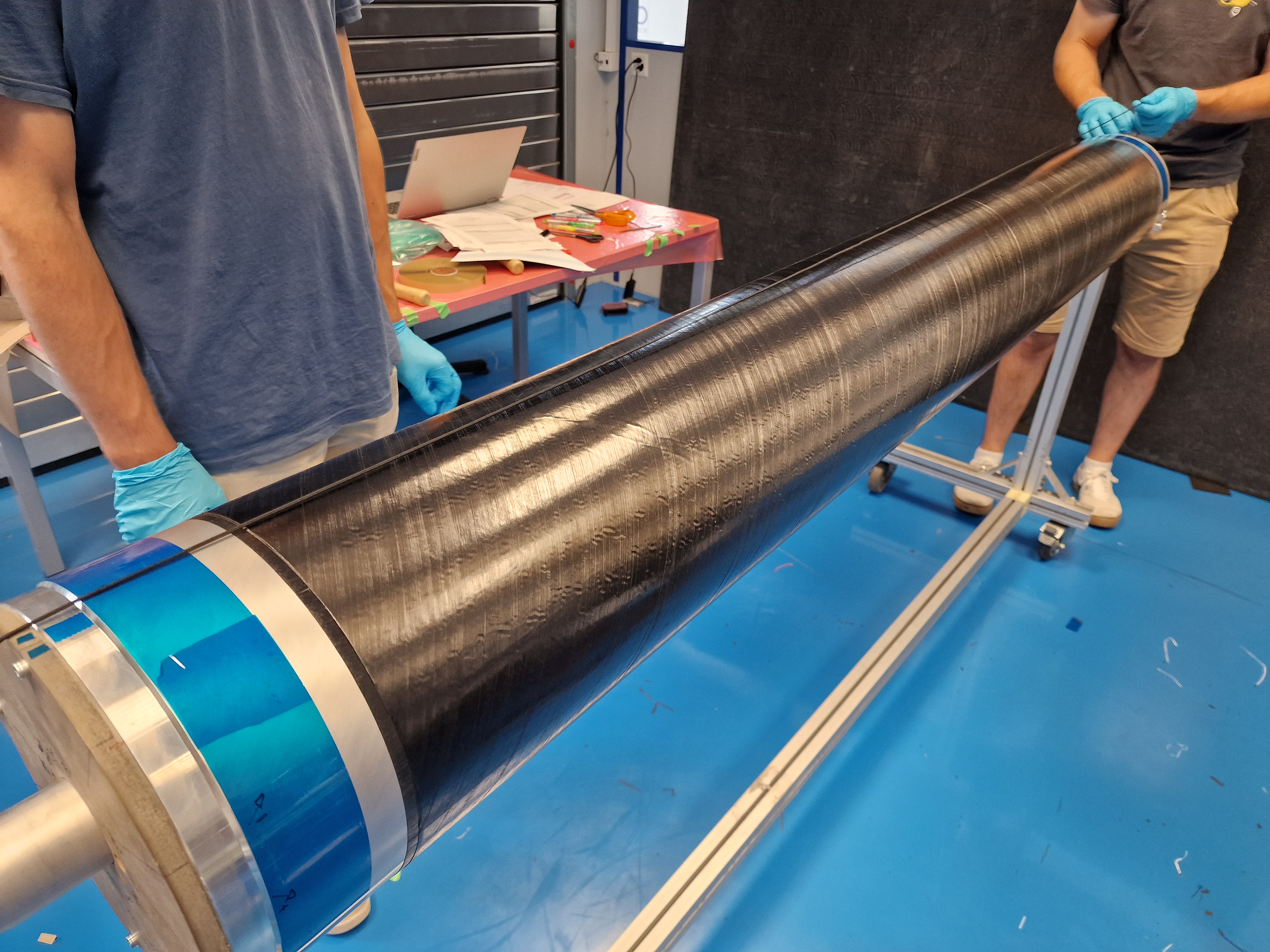
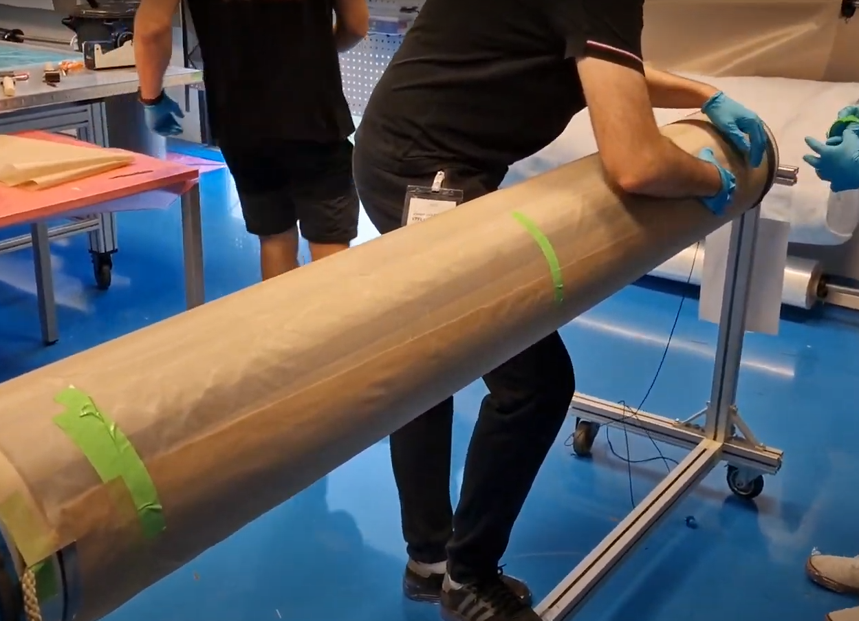
¶ Mandrel preparation
- Mount the mandrel on the trolley jig.
- Clean the surface with dry clothes (alcohol)
- Apply last coating layer of mould release
3.1 Wet the paper towel with XTEND ACR-HS until it is wet but not dripping.
3.2 Gently squeeze the towel into a ball to soak the AXEL XTEND ACR-HS throughout the towel.
3.3 Wipe on to the mold surface using smooth even strokes.
3.4 Apply a thin, uniform coating and allow the release agent to evaporate.- Using a clean cloth lightly wipe over the surface removing any excess release agent
- Wait 1 hour
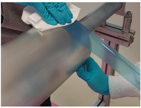
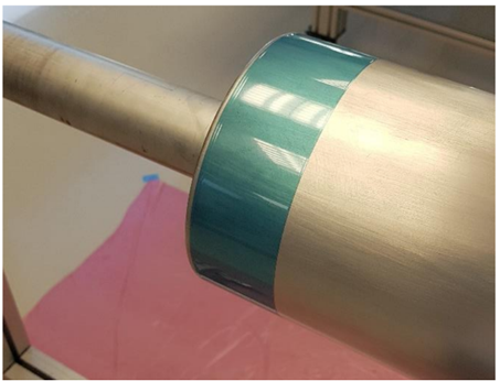
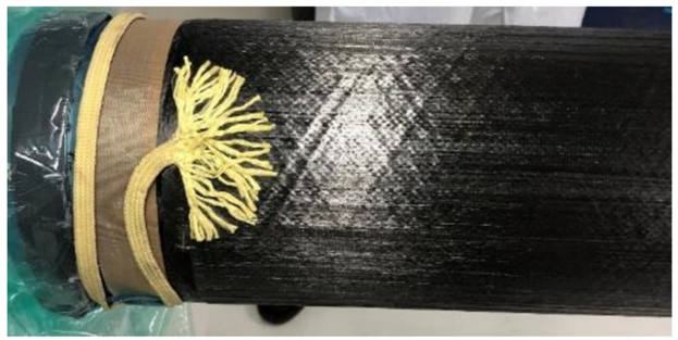
- Apply a thick Teflon tape (around 5cm wide) to either end of the mandrel, while ensuring there is no wrinkle in the tape.
Failure to do so may result in leakage during vacuuming
 |
 |
|---|---|
| Application of the tape | Properly applied tape |
- Tape the edges with scotch "carrossier".
- Draw a rosette on the tape with clear indication of axis.
- Draw sectors on the tape depending on the distance between the junctions of each layer
These are references for the lay-up application
¶ Consumables cutting
¶ Kevlar cord
- Dimensions ~ 500 [mm]
- Cut two pieces of cord.
- Separate filaments at edges.
The cord is used to help demoulding. Separating the edges allows to bond the cord to the curing plies.
Be careful not to cut consumables too soon(vacuum bag, TVT non-porous, film release etc). They can be damaged by tools or become dirty.
¶ Prepregs cutting
Number of operators needed : 2
The cutting patterns are given as a technical drawing
For Firehorn I, the UD carbon had two different types of protection. One was plastic, the other paper. We found that it was preferable to keep the paper when draping, and therefore to remove the plastic, as the rigidity of the paper prevented us from separating the fibers from each other and creating imperfections during marouflage.
Don't use PTFE tape to keep together the cuts, It creates too much stress during draping. It is preferable to use bodywork tape.
¶ 1. Raw cut 0°
- The biggest ply is taken as a reference for raw cuts. (technical drawing)
- Cut UD strips to desired length
- Tape together the strips using bodywork tape. Keep a narrow but open joint (about 0.5mm at a glance).
- Write the number of the obtained ply, the fiber orientation and a square that will be checked once the layer has been ground to the correct size.
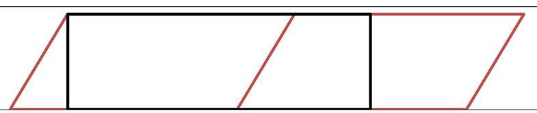
¶ 2. Raw cut 60°
- The biggest ply is taken as a reference for raw cuts. (technical drawing)
- Draw lines at 60° from the main axis of the roll.
- Cut parallelogram strips from the UD roll.
- Tape together the strips using bodywork tape. Keep a narrow but open joint (about 0.5mm at a glance).
- Write the number of the obtained ply, the fiber orientation and a square that will be checked once the layer has been ground to the correct size.
Be careful with the orientation.
 |
 |
|---|---|
| 60 degrees strips cut from prepreg roll | 60 degrees layer cut from 60 degrees strip taped together |
¶ 3. Resizing 0°
- Measure the circumference of the stacking on the mandrel.
- Adjust the raw cut to its final dimension with an offset.
- Fill the square drawed on the layer to validate th resizing.
Use an Excel file to store the value obtained from the circumference measurement. After 3 measurements, you can calculate an average of the increase in diameter and use this value to cut the following layers.
¶ 4. Resizing 60°
- Measure the circumference of the stacking on the mandrel.
- Adjust the raw cut to its final dimension with an offset.
- Fill the square drawed on the layer to validate the resizing.
¶ 6. Sort the plies by numbering
It is expected that each side of the prepreg is covered with a different coloured paper.
- Decide on how to differentiate plies at 60° and plies at 60°.
- Write down the chosen rule and stick to it.
- Number the plies according to the chosen rule.
The chosen rule is the responsibility of the COO
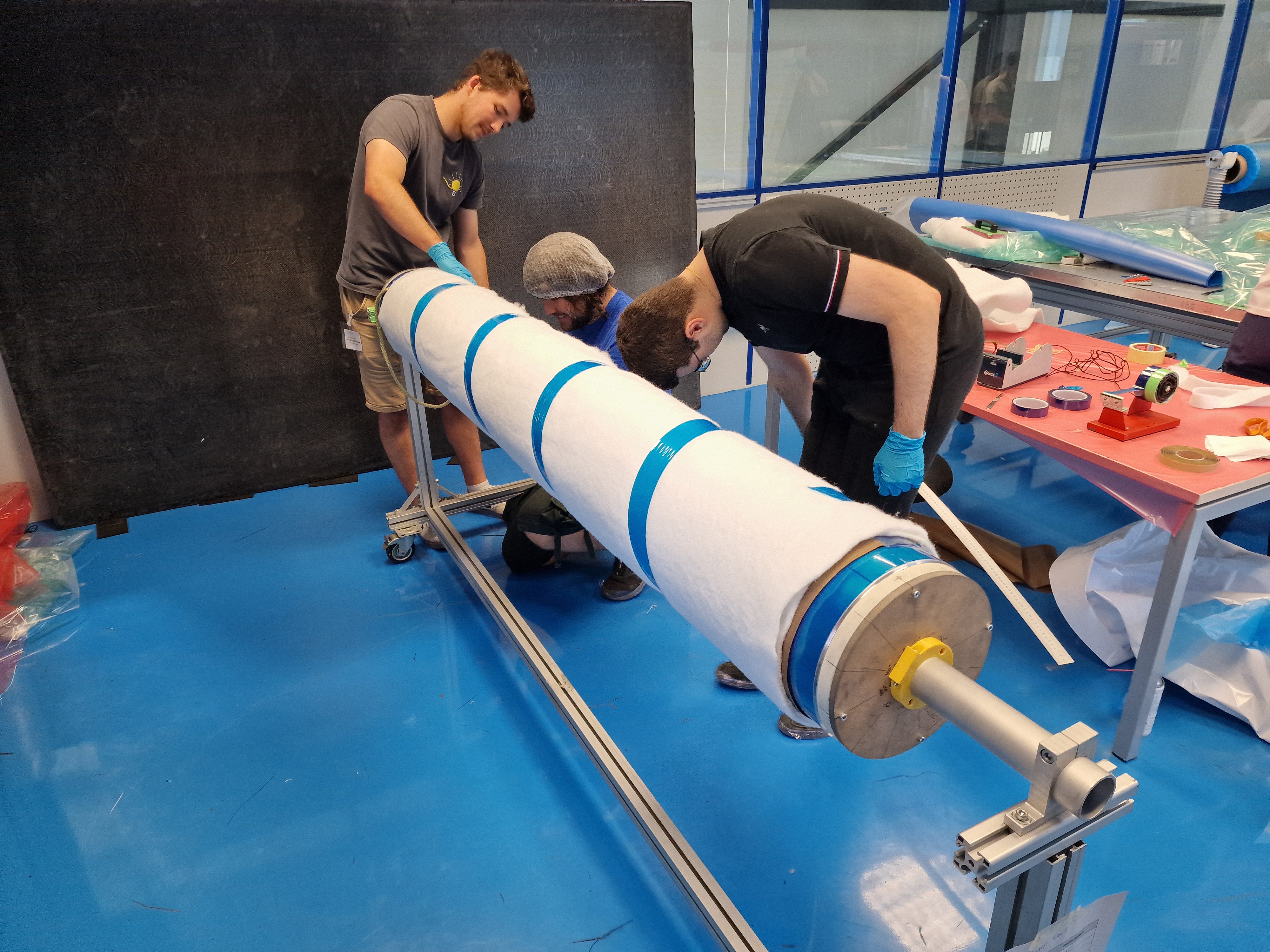
¶ Lay-up
The operator must sign each time a ply is layed-up
The COO have to verify that intermediate vacuuming has been done before allowing the application of next ply
Rotate the mandrel by 30° after each ply
Place a piece of paper next to the mandrel on which is written the mandrel sector to apply the layer (0°, 30° etc.), the layer number, the fiber orientation and the intermediate vacuum. Be flexible when it comes to intermediate vacuum. If the layer has not been perfectly draped and you have a few bubbles, or if the layer does not adhere well to the underlay, make an intermediate vacuum even if it is not written on the control sheet.
| n°layer | Orientation [°] | Mandrel orientation [°] | Check |
|---|---|---|---|
| 1 | 0 | 0 | |
| Vaccum | 10 [min] | ||
| 2 | 60 | 30 | |
| 3 | -60 | 60 | |
| Vaccum | 10 [min] | ||
| 4 | -60 | 90 | |
| 5 | 60 | 120 | |
| Vaccum | 10 [min] | ||
| 6 | 0 | 150 | |
| middle | Insert Kevlar cord | ||
| 7 | 0 | 180 | |
| Vaccum | 10 [min] | ||
| 8 | 60 | 210 | |
| 9 | -60 | 240 | |
| Vaccum | 10 [min] | ||
| 10 | -60 | 270 | |
| 11 | 60 | 300 | |
| Vaccum | 10 [min] | ||
| 12 | 0 | 330 | |
| Vaccum | 10 [min] |
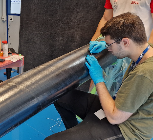
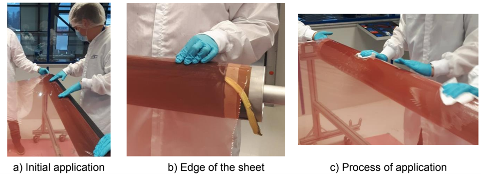
¶ How to apply prepreg ?
Number of operators needed : 3 - 4
Watch the videos from the 2024 session to better understand how to apply the layers.
- Stretch a rope along the mandrel and align it with the correct sector
- Align the prepreg with the rope
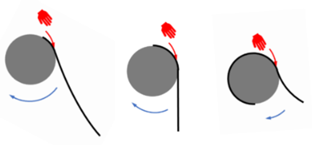
- Start applying the layer from center to edge.
Always roll the prepreg around the mandrel in the same direction.
Do not press too hard on the layer when draping. Use enough force to push out the bubbles and apply the layer. Pressing too hard risks separating the fibers and creating ribs.
For the 60° layer, remove bubbles from the center to the sides, then apply in the direction of the fibers.
- Turn the mandrel slowly when the layer is well applied.
- When a quarter of the layer has been applied, let the layer hang. No operator touches the free end.
Do not forget to remove patchworking tape
 |
|---|
 |
|---|
 |
|---|
|| |
|
|:--
 |
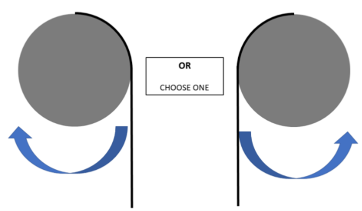 |
|---|---|
| Marouflage theory | Side view, one must be chosen as reference and not changed |
Do not forget to remove patchworking tape
Layer resizing based on diameter measurements produces a layer that perfectly matches the circumference. However, inaccurate cutting or poor draping can result in either an overlap or a gap.
Only 1mm gap per meter is acceptable.
No overlap is acceptable
In the case of an overlap :
- Place a metal ruler under the overlap.
- Place a 2nd ruler on the layer and on the ruler.
- Align the top ruler with the point where the overlap ends and with the width to be cut.
- Cut the overlap with a cutter.
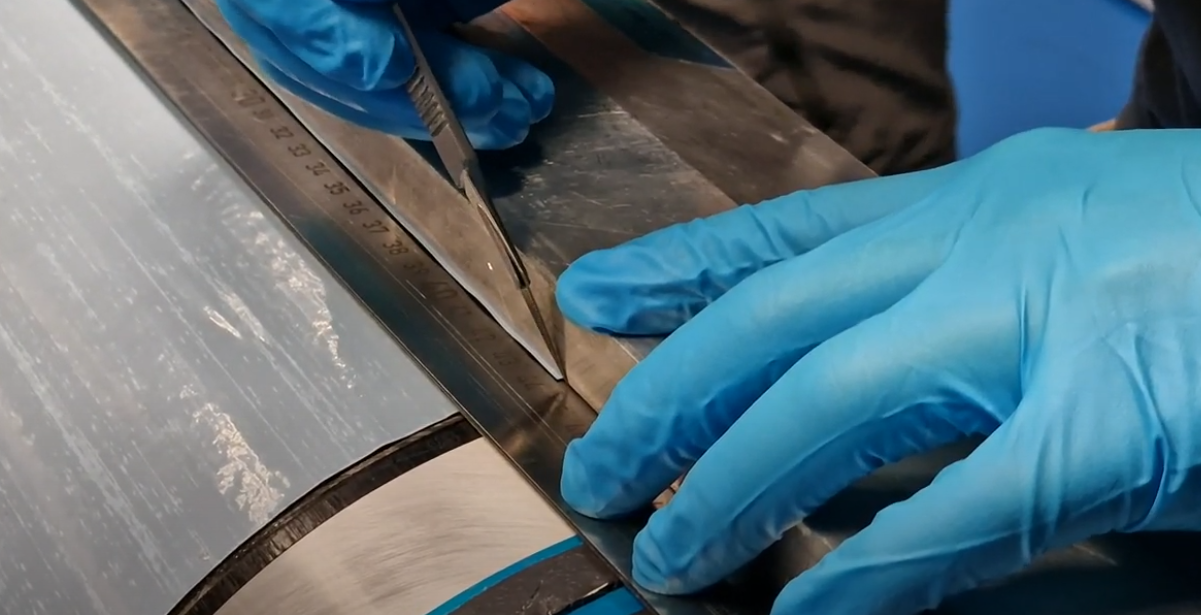 |
|---|
| Cut the overlap with 2 ruler and a cutter/scalpel |
In the case of a gap :
- Cut a strip the same size as the gap and the same orientation as the layer
- Apply the strip to the gap. Do not create an overlap with the strip
 |
|---|
| fill the gap with a strip |
¶ Kevlar Cord
Don't forget to place the rope halfway up the drape.
 |
|---|
| Kevlar cord with separated edges |
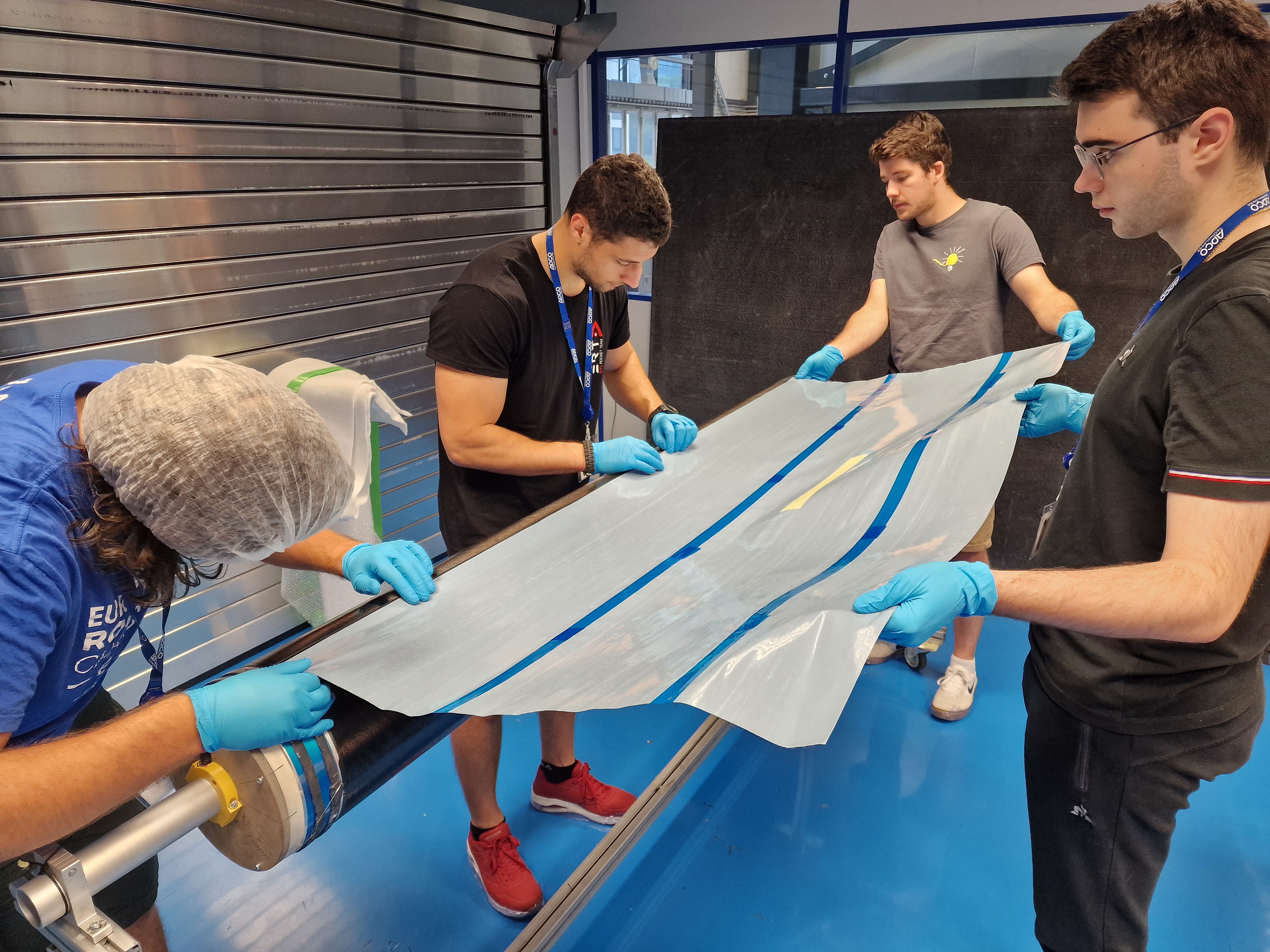
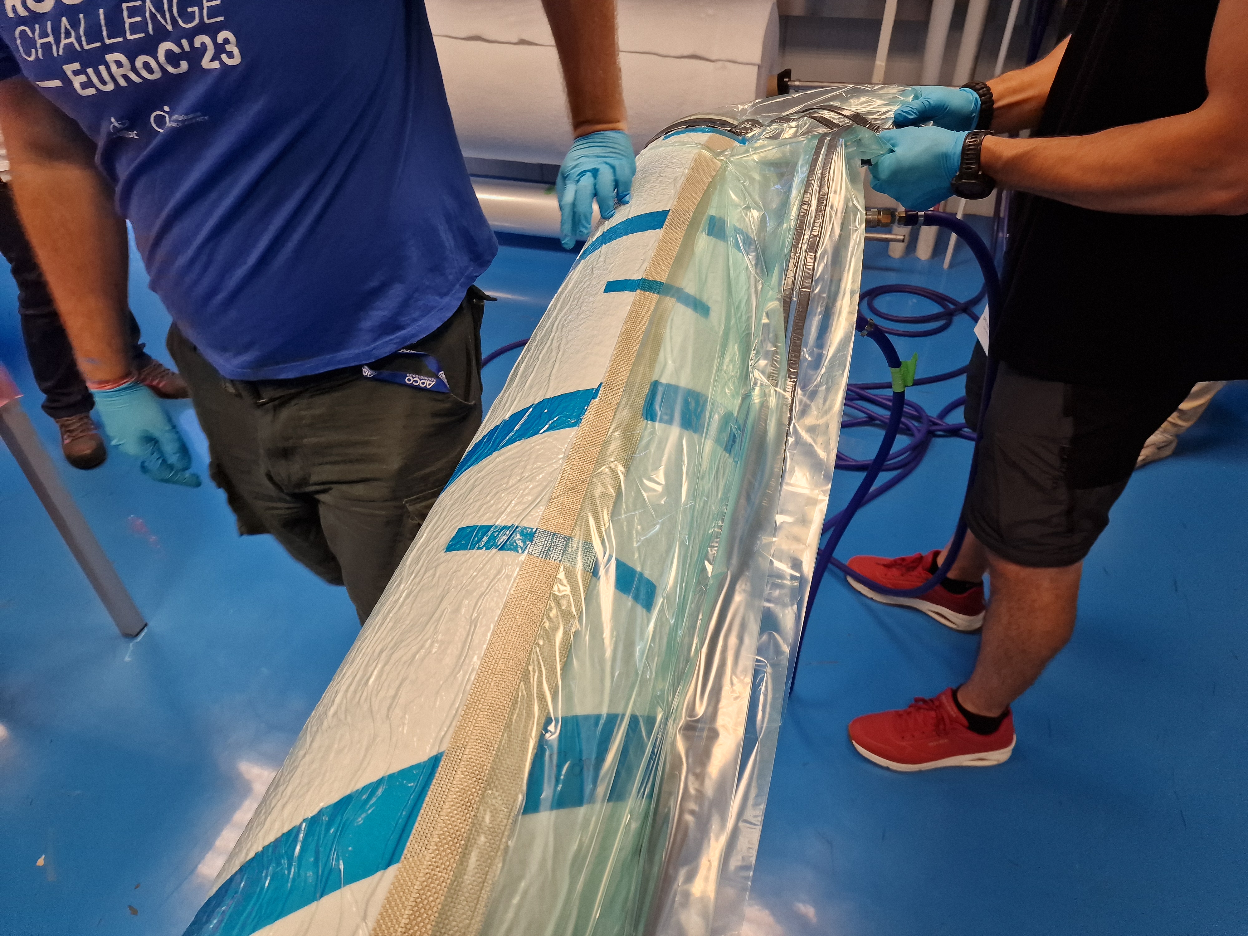
¶ How to intermediate vacuum ?
Number of operators needed : 3 - 4
Watch the videos from the 2024 session to better understand how to do a intermediate vacuum.
Let the carbon protective film during the vacuum
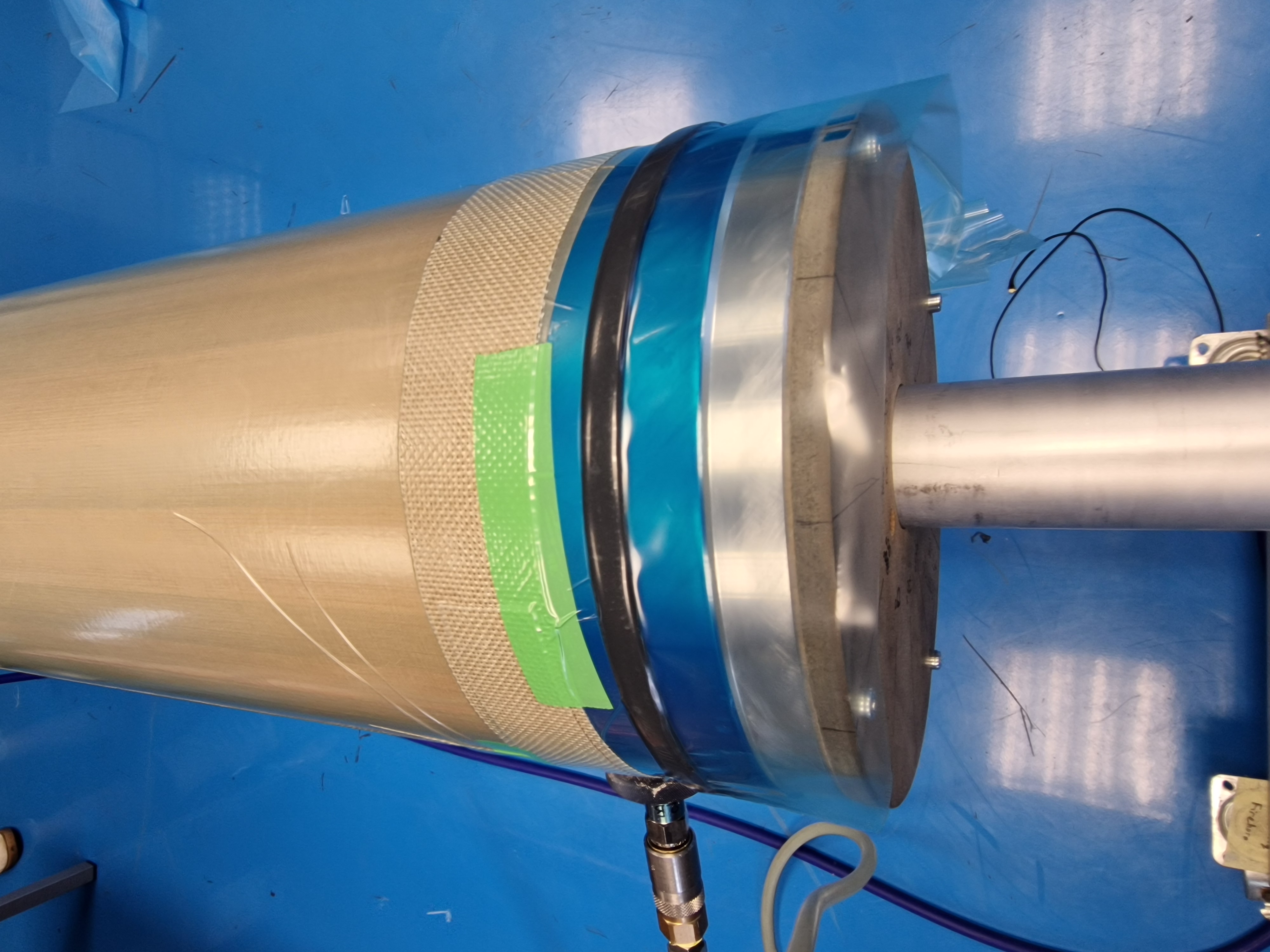
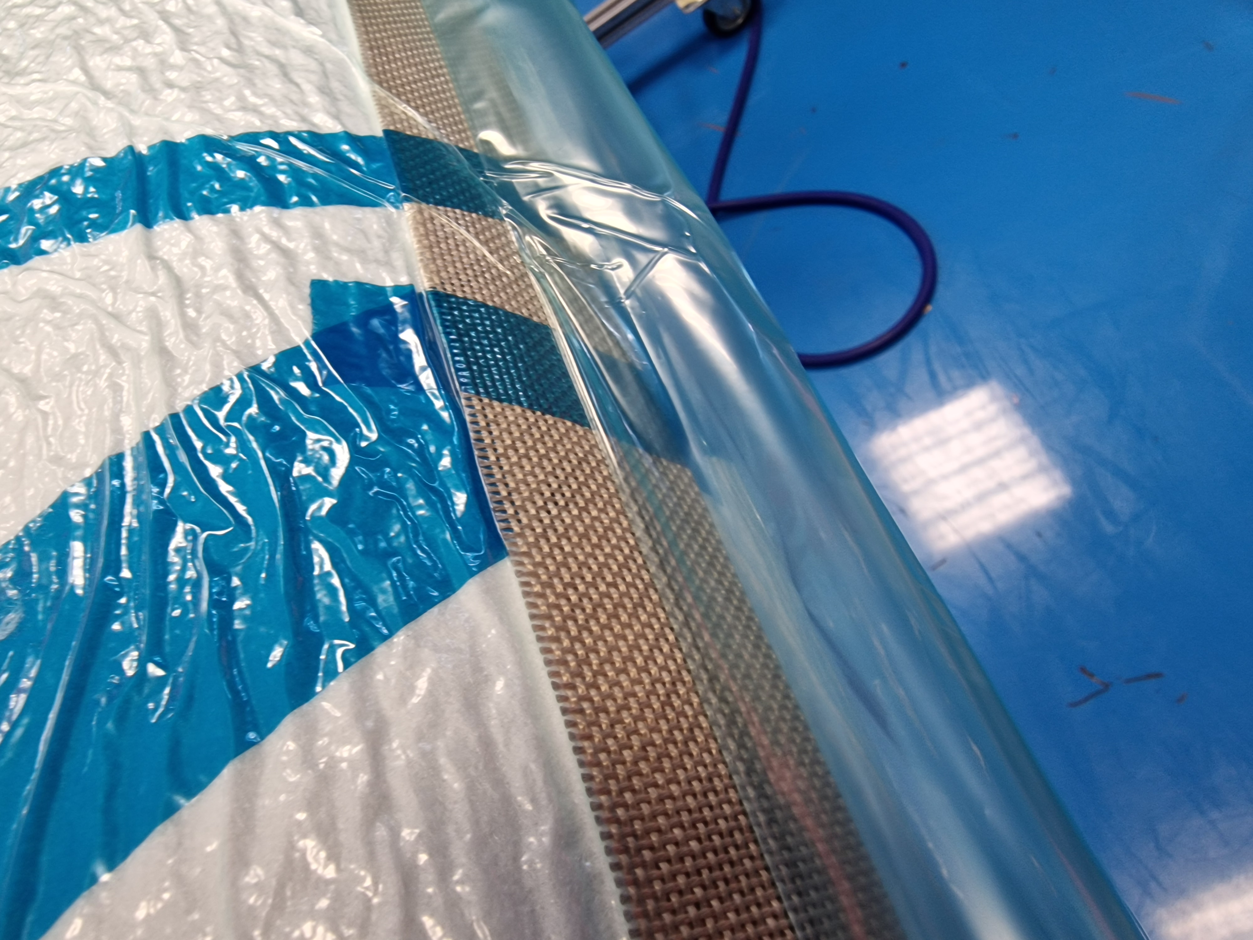
- Cut porous TVT (about one and a half times the circumference)
- Roll porous TVT around the mandrel.
- Secure the TVT with green PTFE tape. Make sure it's taut and wrinkle-free
- Apply a strip of tacky tape to the blue PTFE tape on both ends of the mandrel.
- Roll two strips of grid breather on both end of the TVT porous.
- Secure the strips with green PTFE tape.
- Join the two strips with another strip of grid breather along the mandrel.
- Secure the long strip with green PTFE tape.
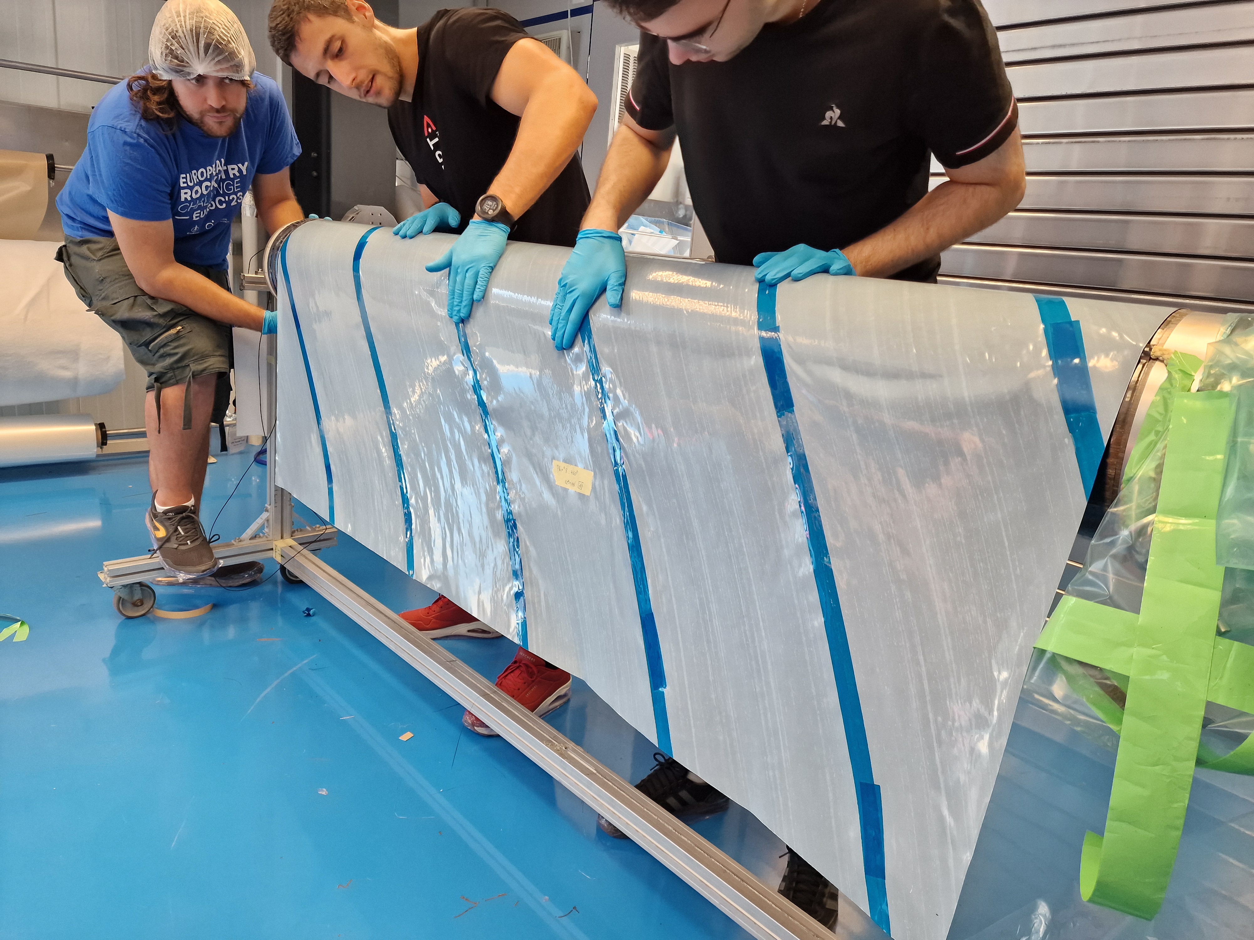
- Cut the vacuum bag. (Twice the mandrel cicumference)
- Place an uncut edge of the vacuum bag along the mandrel
- Stick the vacuum bag to the tacky tape
- Roll the vacuum bag around the mandrel.
- Unstick the first edge (around 30 cm to unstick)
- Let the unstick edge and the rest of the vacuum bag hang.
- Place two vacuuming discs on the two grid breather strips at the ends of the mandrel.
- Stick a strip of tacky tape along the unstick vacuum bag edge. Let 10 cm free.
- Stick a strip of tacky tape on both end of the vacuum bag. The strips must join the longitudinal tacky tape of the bag and the tacky tape placed on the blue tape of the madrin.
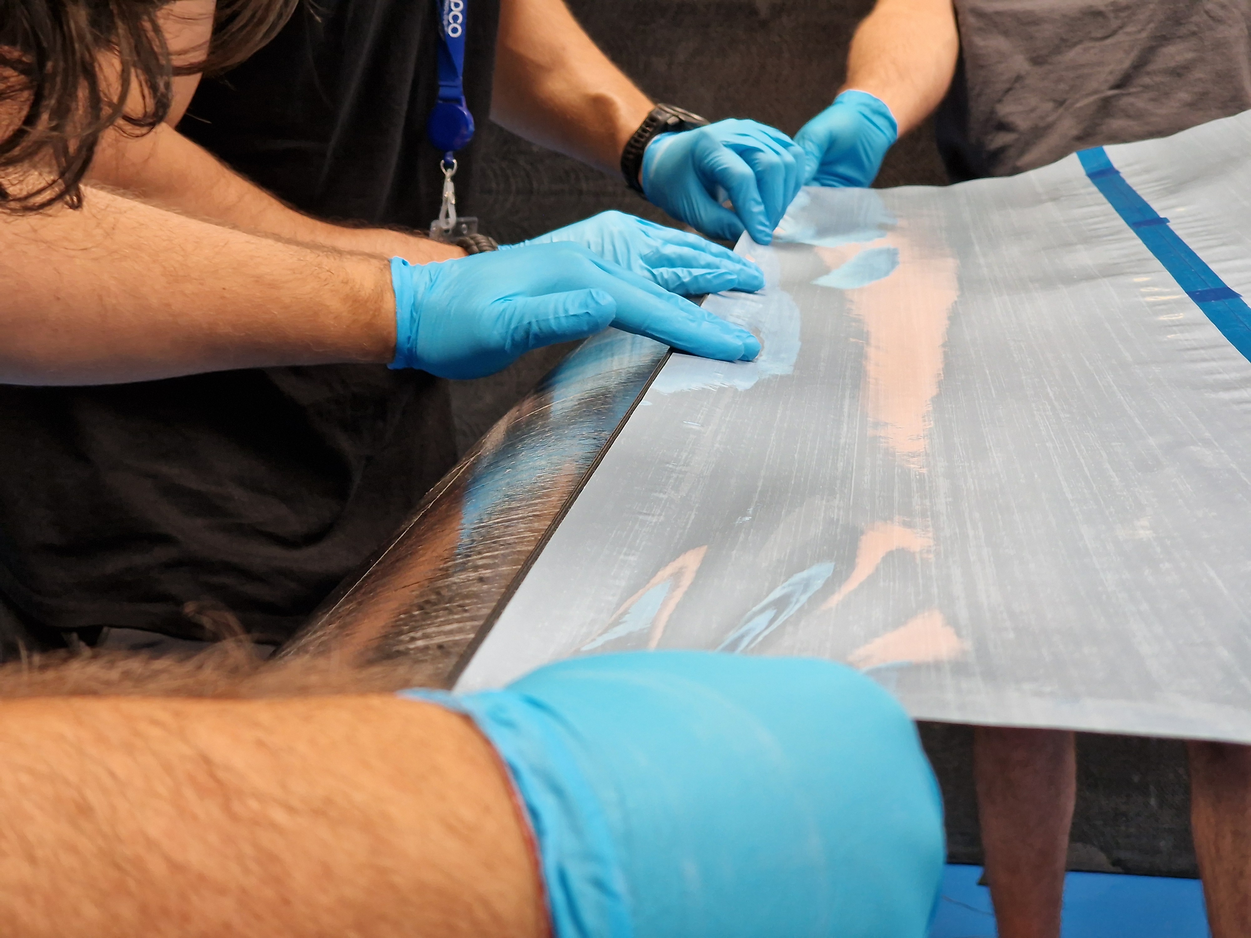
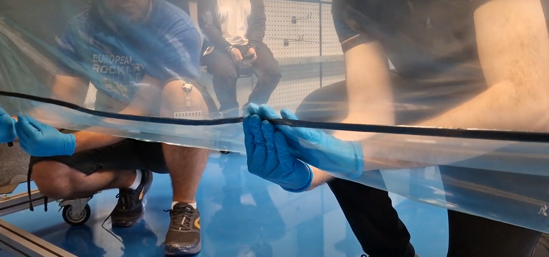
- Starting from the center of the vacuum bag, stick the two edges together. Make sure there are no wrinkles or leaks.
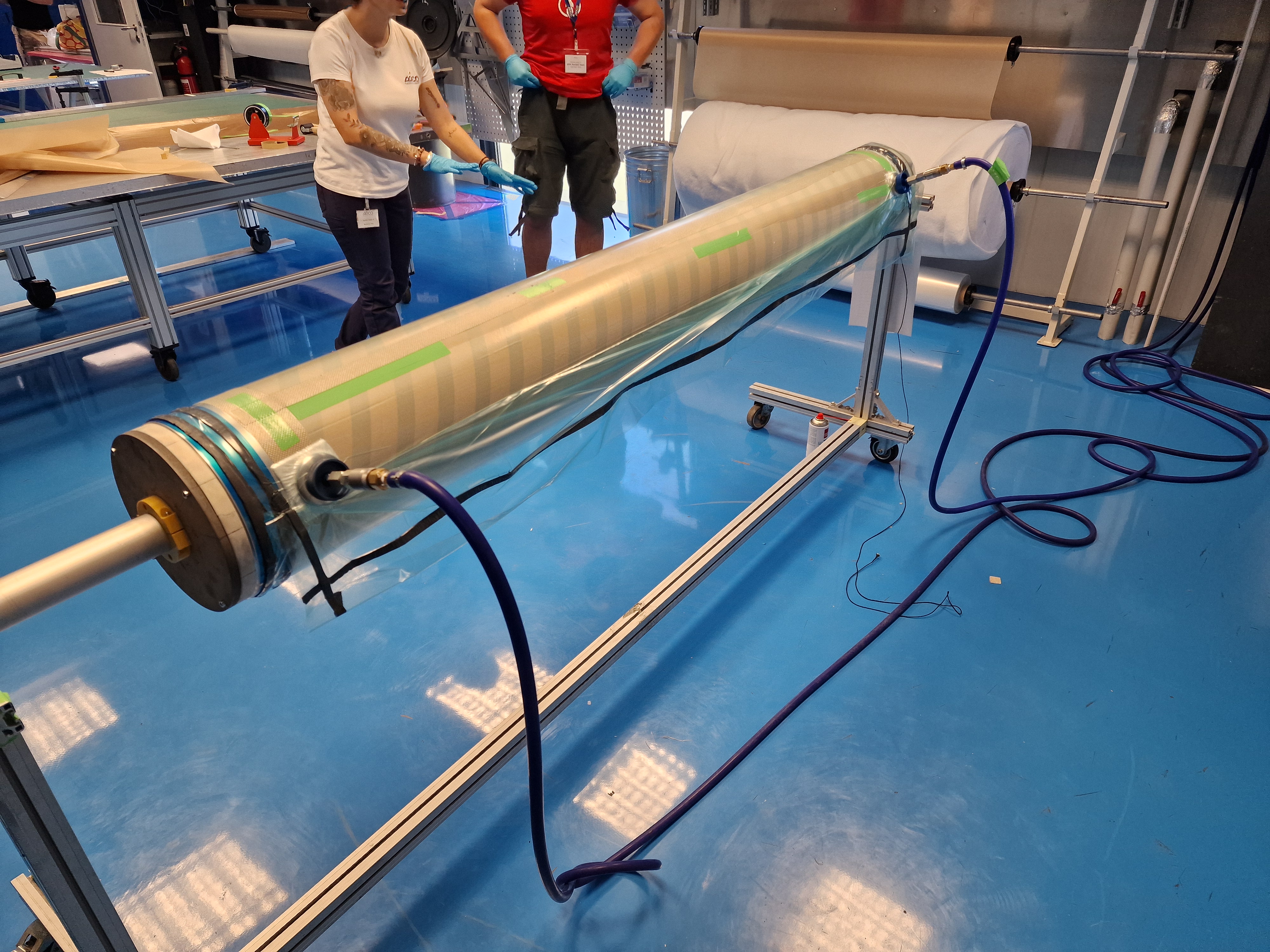
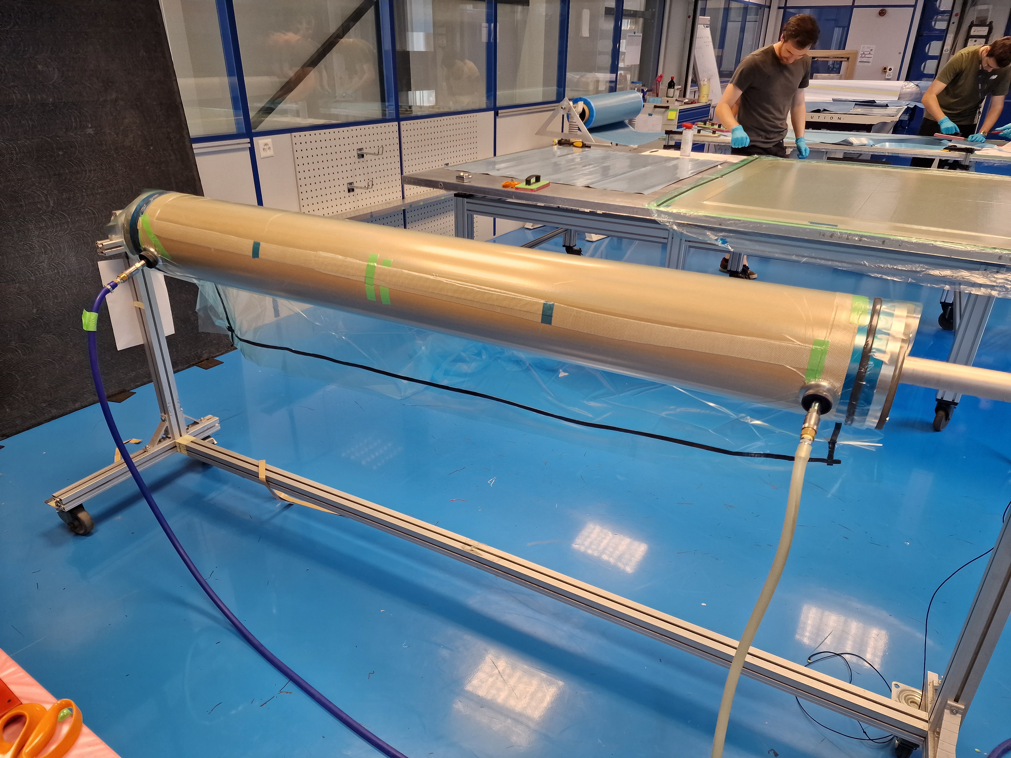
- Place the first asspiration and stretch the vacuum bag downwards. make sure the bag is smooth on the tube.
- When the bag is correctly positioned, apply the second vacuum.
- Vacuum
 |
|---|
 |
|---|
 |
|---|
 |
|---|
 |
|---|
After vacuuming, open the bag on one side and at the bottom, then remove it towards the side still stuck, to save it for the next vacuum. If the vacuum bag is too damaged, you'll need a new one.
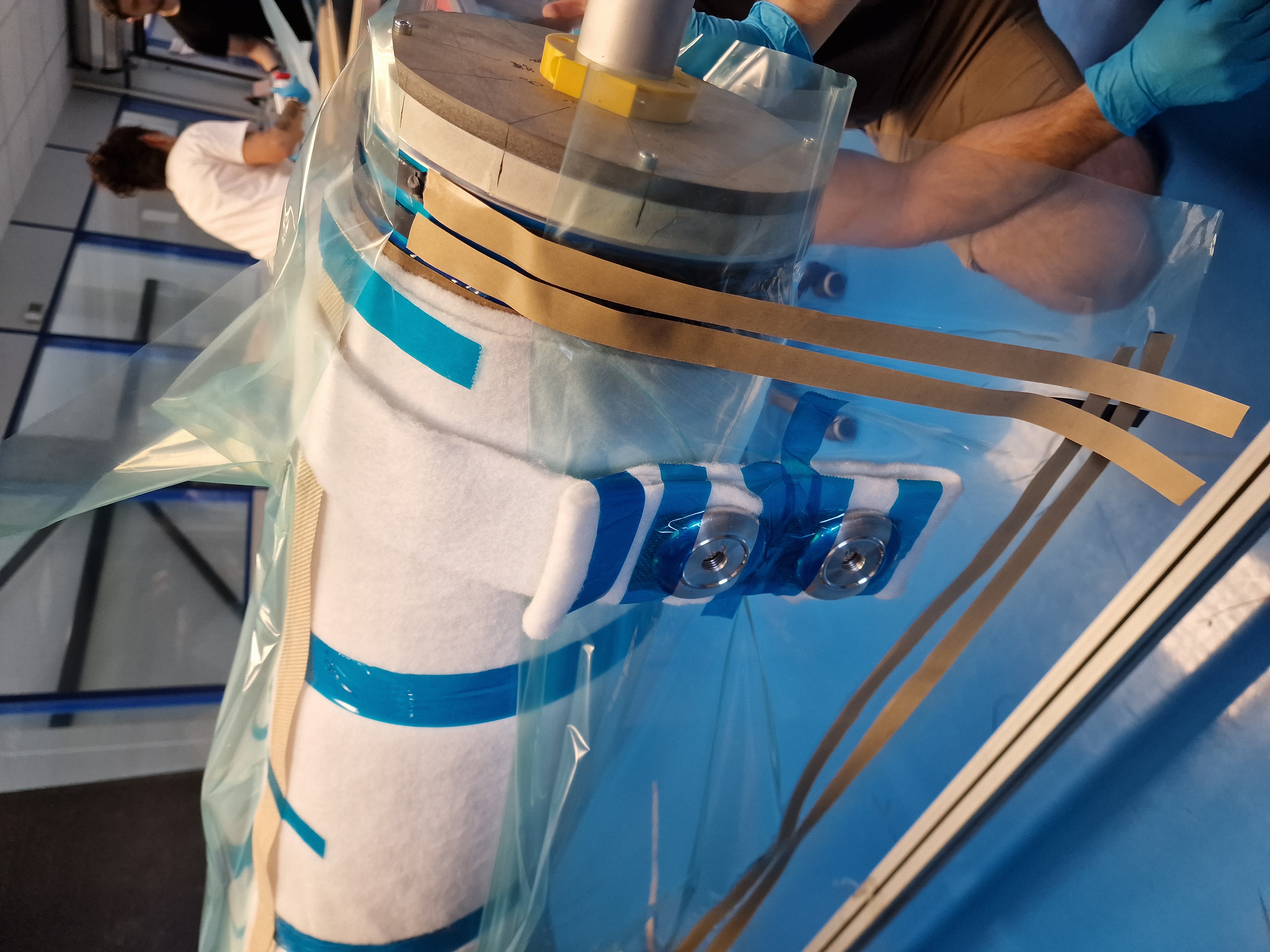
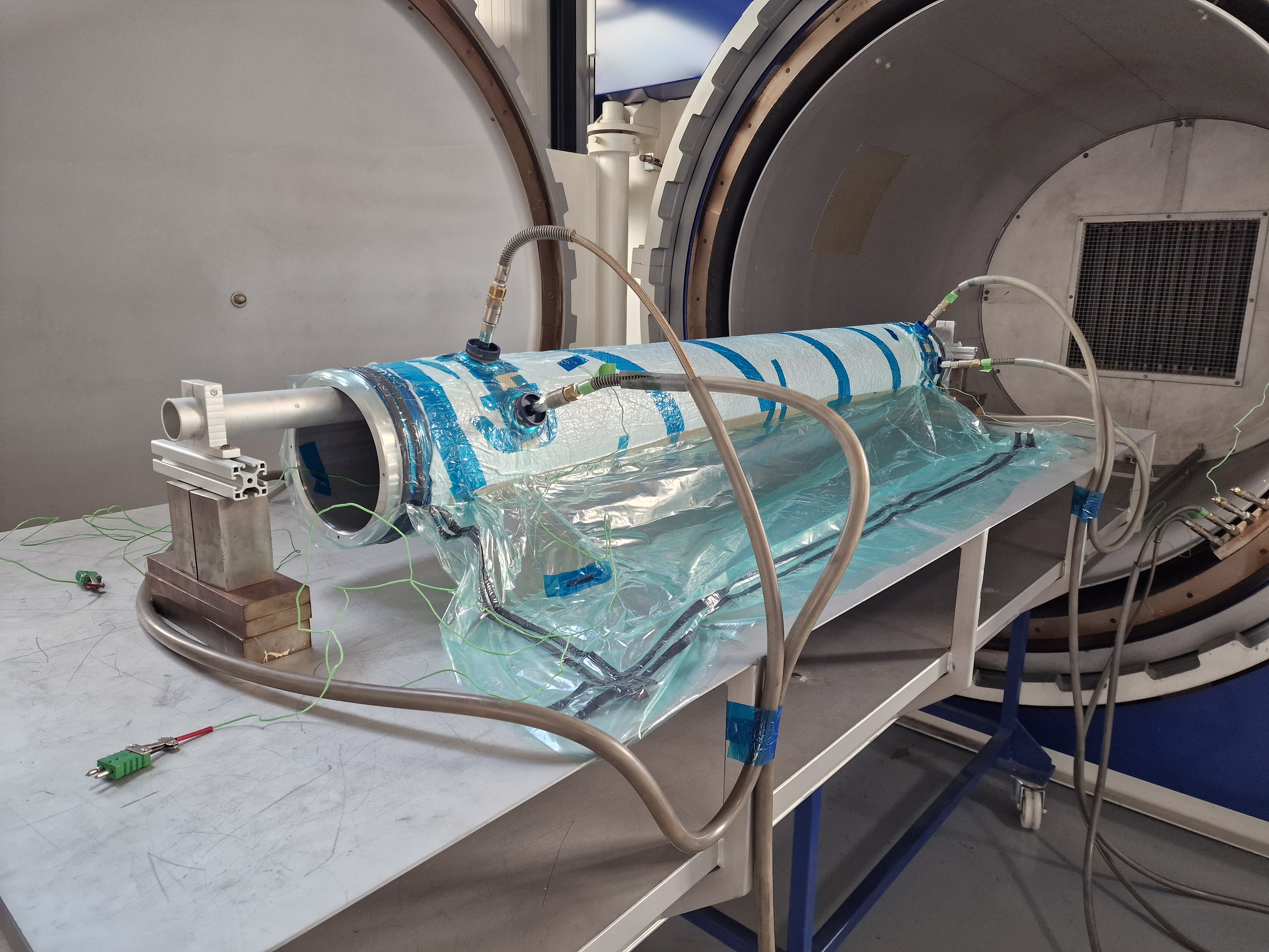
¶ Final vacuum
Number of operators needed : 3 - 4
{.is-info}
Watch the videos from the 2024 session to better understand how to do a final vacuum.
- Photos and videos from the 2024 session
{.links-list}X
- Remove the protective film from the last layer.
- Cut film release twice the circumference of the tube.
The film release gives the shiny surface finish
- Roll the film release twice around the tube starting from 0° junction.
- Secure with blue PTFE tape.
Any wrinkles on the film will show on the tube
For all consumables, secure with blue PTFE tape only on the edge of the tube. There must be no tapping on the usable part of the tube, otherwise a mark will be visible on the carbon tube.
Consumables must not protrude over the blue PTFE tape on either end of the mandrel
 |
|---|
| Wrapping with film release |
- Cut the TVT non-porous twice the tube circumference.
- Roll the TVT non-porous arround the tube starting from the 180° junction.
- Secure with blue PTFE tape.
- Apply two strips of tacky tape on the mandrel circumference at both ends.
 |
|---|
- Cut the breather twice the tube curcumference.
- Roll twice around the tube.
- Secure with blue PTFE tape with a single strip and spiral-wrap.
 |
|---|
- Place a strip of grid breather along the tube over the white breather joint.
- Secure the long strip with blue PTFE tape.
- Cut the vacuum bag. (Twice the mandrel cicumference)
- Place an uncut edge of the vacuum bag along the mandrel
- Stick the vacuum bag to the tacky tape
- Roll the vacuum bag around the mandrel.
- Unstick the first edge (around 30 cm to unstick)
- Let the unstick edge and the rest of the vacuum bag hang.
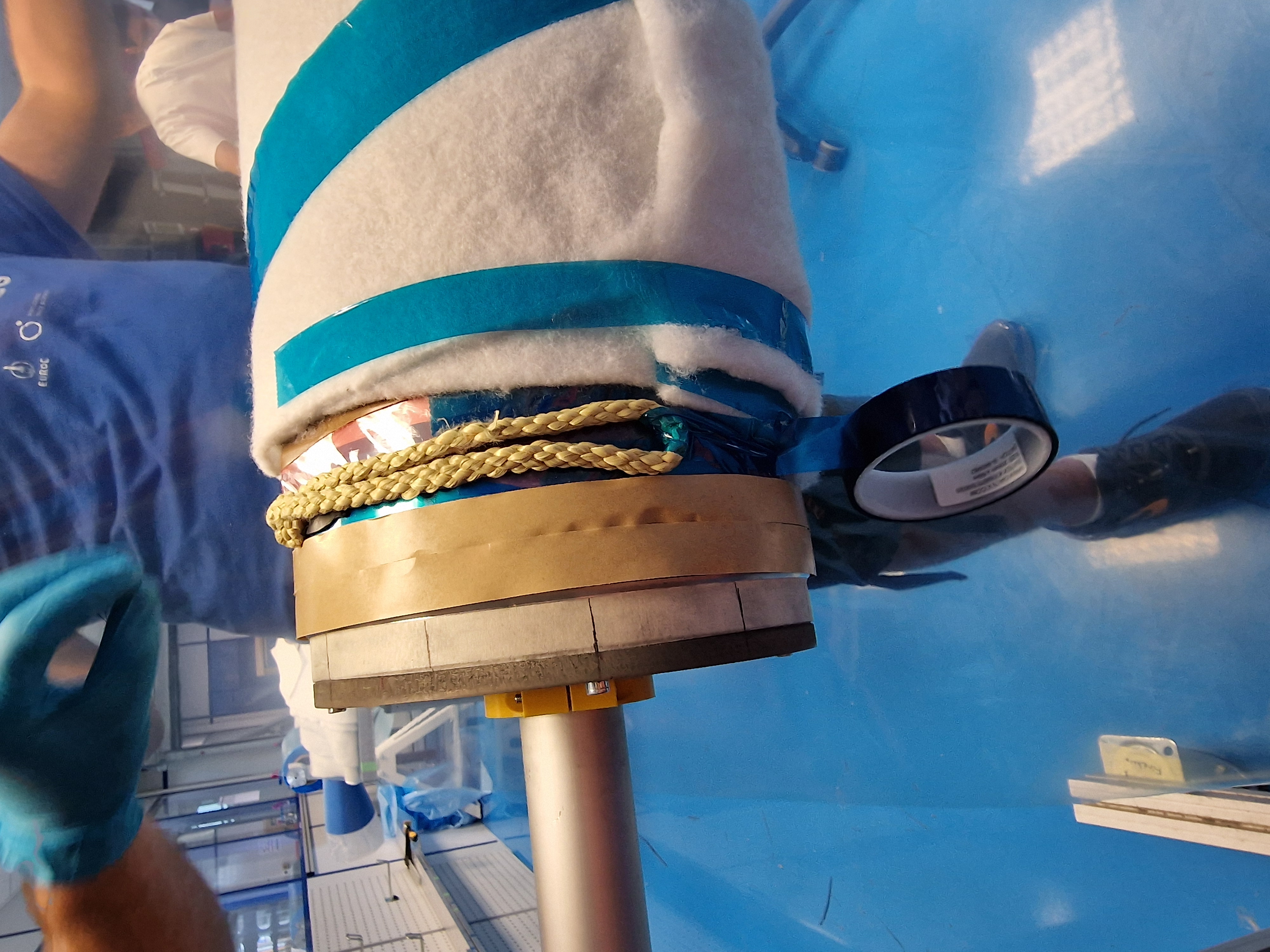
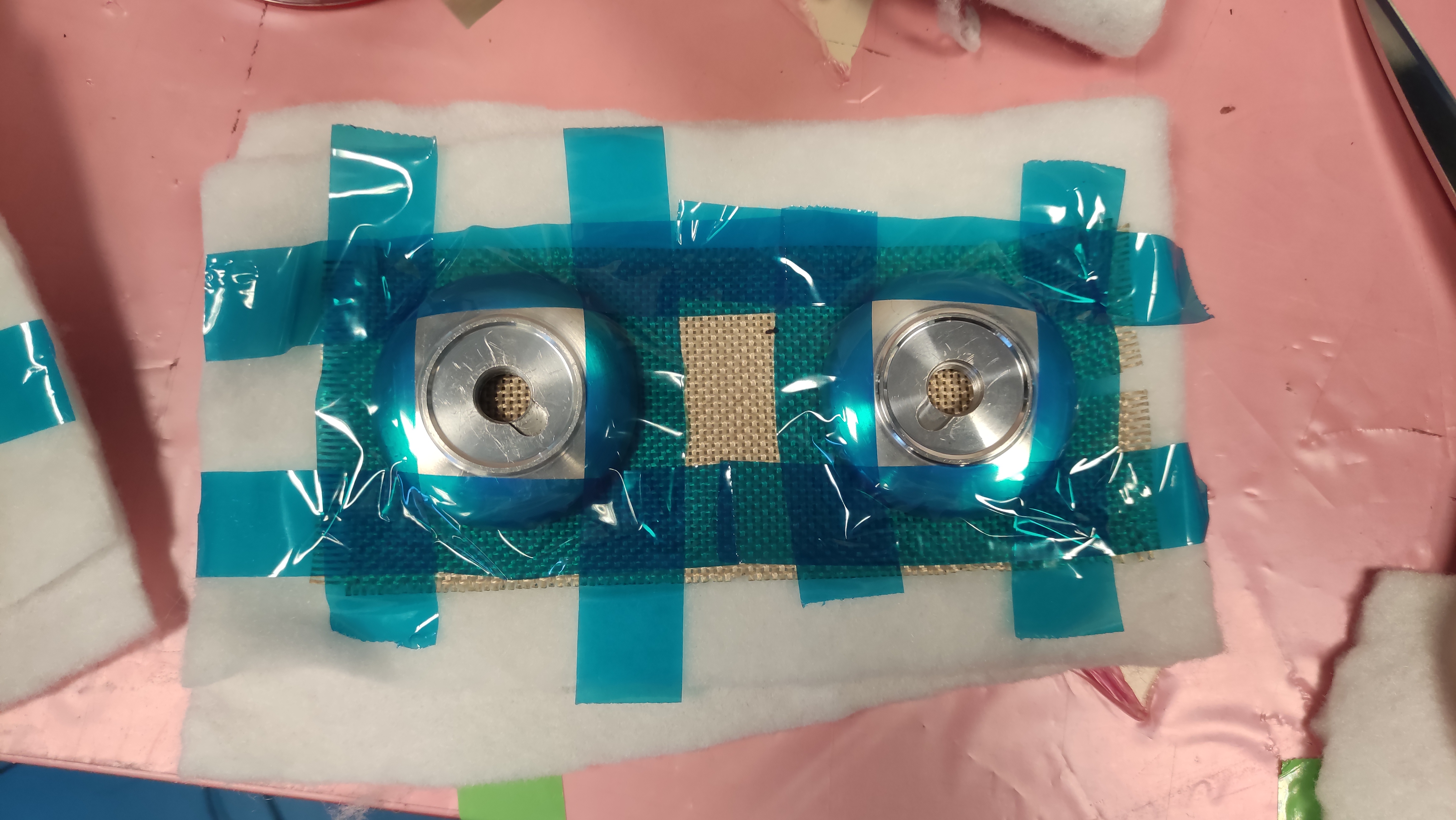
- Make sure the ear joint is over the grid breather.
- Prepare 2 sets of 2 vacuum discs with 6 layers of breather like the picture below.
- Place both sets on both ends of the tubes.
 |
|---|
 |
|---|
 |
|---|
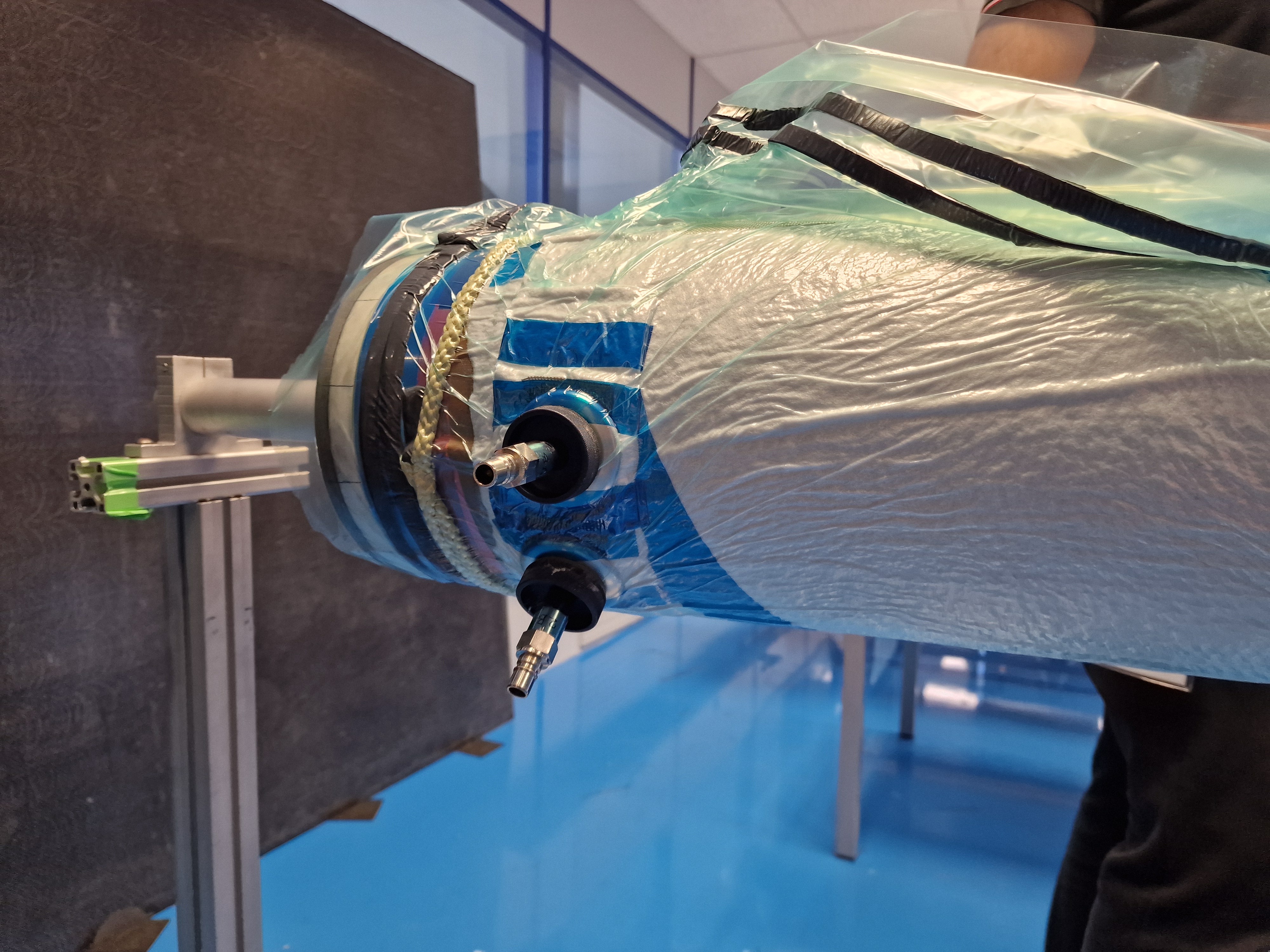
- Stick two strips of tacky tape along the unstick vacuum bag edge. Let 10 cm free and let 3 cm between the two strips.
- Stick two strips of tacky tape on both end of the vacuum bag. The strips must join the longitudinal tacky tape of the bag and the tacky tape placed on the blue tape of the madrin.
- Starting from the center of the vacuum bag, stick the two edges together. Make sure there are no wrinkles or leaks.
- Place the first asspiration and stretch the vacuum bag downwards. make sure the bag is smooth on the tube and that the ear joint is over the grid breather.
 |
|---|
 |
|---|
- When the bag is correctly positioned, apply the rest of vacuum.
- Vacuum 10 min
- Drop test 10 min
 |
|---|
¶ Curing cycle
¶ 1. Curing
- Time: 320 [min]
- Heat the part to 60 [°C] with a speed of 2 [°C.min−1]
2.Keep it at 60 [°C] for 30 [min] while applying 5 [bar] of pressure- Heat the part to 120 [°C] with speed of 2 [°C.min−1]
- Keep it at 120 [°C] for 180 [min]
- Cool the part to 20 [°C] with speed of 2 [°C.min−1]
- Depressurise the autoclave
- Mandrel Freezing
- Demoulding
¶ 2. Post-curing
Post-curing will be done without the mandrel
- Time: 380 [min]
- Heat the part to 120 [°C] with a speed of 2 [°C.min−1]
2.Keep it at 120 [°C] for 30[min] while applying 5[bar] of pressure- Heat the part to 180[°C] with speed of 2 [°C.min−1]
- Keep it at 180[°C] for 180[min]
- Cool the part to 20[°C] with speed of 2[°C.min−1]
- Depressurise the autoclave
¶ Post Conditions
| Check | Step | Description | Image |
|---|---|---|---|
| 1 | Check for wrinklings | ||
| 2 | Check for cracks | ||
| 3 | Check the inner surface | ||
| 4 | Do some dimension checks |
- Theoretical thickness = 380 [min]
¶ General Comments
¶ Questions for Gavin
- Can we clean the coated mandrel with alcohol ? or it will dissolve the mould release?
- Pas besoin d'alcool pour nettoyer le mandrin lorsque le mould release et appliqué, chiffon sec et propre suffit.
- Is it recommanded to have an auto-overlapping joint for a given ply ? Or it is better to have an open joint ?
- Pas d'overlap de la meme couche pour les UD
- For "compactage", what type of consumables are recommanded to put between prepregs and vacuum bag (in case we don't have textured bag) ?
- Utilisation de peelply
- Good pattern when rotating the ply joints ? ("étoiles" ? tourner de X° à chaque fois ?)
- Pattern en UD pas besoin de faire en croix, rotation du mandrin dans le meme sens va très bien
- Curing cycle suuggestion ? (Our target is 180°C)
- Datasheet
General suggestions:
- C'est préférable de poncer/polir le mandrin
- Si possible compacter a chaque plie pour eviter les veines