¶ Introduction
¶ Definitions and Abbreviations
- RE: Recovery
- REB: Recovery Bay
- AVB: Avionics Bays
- SM: Separation Mechanism
¶ Applicable and Reference Documents
- 2024_C_ST_RECOVERY-BAY_DDF
- 2024_C_ST_SHOCKPLATE_DDF
- 2024_C_ST_RE_LLIM
- 2024_C_ST_SEPARATION_MECHANISM_DDF
- 2024_C_ST_SEPARATION_MECHANISM_TSP
- 2024_C_ST_COUPLERS_DDF
- 2025_C_ST_RECOVERY-BAY_PURPOSE_IR
- 2025_C_ST_Shockplate_FEA
- 2025_C_ST_RECOVERY_BAY_MAP
¶ Requirements
The Recovery bay must meet and comply with the following requirements:
- 2024_C_SE_ST_RECOVERY-BAY_REQ_1
Recovery bay declaration of purpose
The recovery bay shall host the RE systems of the LV.
The recovery team has performed a successful integration of their components, consisting mainly of the parachute, the swivel, and the shock cords.
Preliminary estimations of RE expected a length of 700 mm:
- 200 mm for the swivel (conservative estimation)
- 350 mm for the parachute
- 150 mm for the ropes
This complies with the intended purpose.
- 2024_C_SE_ST_RECOVERY-BAY_REQ_2
Guiding tube diameter
The recovery bay guiding tube diameter shall be [188][+0/-5] mm.
For more details, please refer to the following document:
- 2024_C_SE_ST_RECOVERY-BAY_REQ_3
Useable length for recovery
The length available for RE shall be at least [600] mm.
For more details, please refer to the following document:
- 2024_C_SE_ST_RECOVERY-BAY_REQ_4
Parachutes attachment
The parachutes shall have a rotating anchor inside the LV.
RE includes a rotating swivel attached to the eyebolt at the top end of the recovery bay. TKK to be verified
- 2024_C_SE_ST_RECOVERY-BAY_REQ_5
Guiding tube attachment
The recovery guiding tube shall remain attached to the recovery bay under an axial tensile load of [4000] N caused by parachute deployment.
This requirement is based on the mass of the recovery system and the expected deceleration during parachute deployment, with an added safety factor. Its purpose is to ensure that the guiding tube remains securely attached and does not detach or eject from the rocket during parachute deployment.
To ensure this requirement is met, the bonding length of the glued interfaces between the caps and the guiding tube has been dimensioned accordingly. In addition, the cap thickness has been increased to withstand a certain load,and the centering ring at the bottom end provide supplementary retention by adding friction to the centering ring.
- 2024_C_SE_ST_RECOVERY-BAY_REQ_6
Bay length
The recovery bay shall have a maximum length of [700] mm.
For more details, please refer to the following document:
- 2024_C_SE_ST_RECOVERY-BAY_REQ_9
RE structure mass
The total mass of the RE bay structure shall be maximum [6000] g.
For more details, please refer to the following document:
- 2024_C_SE_ST_RECOVERY-BAY_REQ_11
Structure type
The recovery bay structure shall be external so that the external tube carries all the flight loads.
This requirement is fulfilled. Instead of rods and anti-buckling rings carrying the loads, the RE tube itself assumes the structural function. For more information, refer to 2024_C_ST_RECOVERY-TUBE_FEA.
- 2024_C_SE_ST_RECOVERY-BAY_REQ_12
Connection to the nosecone
The recovery bay shall be connected to the nosecone bay via a coupler located on the upper recovery bay end.
The connection to the nosecone bay is achieved via a female coupler bonded to the top of the RE tube.
- 2024_C_SE_ST_RECOVERY-BAY_REQ_13
Upper shockplate load case
The shock plate in the recovery bay of the FH I LV shall withstand [4800] N of axial tensile loads.
This requirement is validated through FEA. See the dedicated section on the shock plate and the FEM report.
- 2025_C_ST_Shockplate_FEA Shockplate Finite Element Analysis Report
¶ Interfaces
At the top of the rocket, the interface is formed by a shock plate fitted with an M8 helicoil to secure the eyebolt. It is attached to the cap of the guiding tube and the female coupler using M4 screws. During parachute deployment, the shock plate transfers the load to the coupler, distributing the force throughout the rocket.
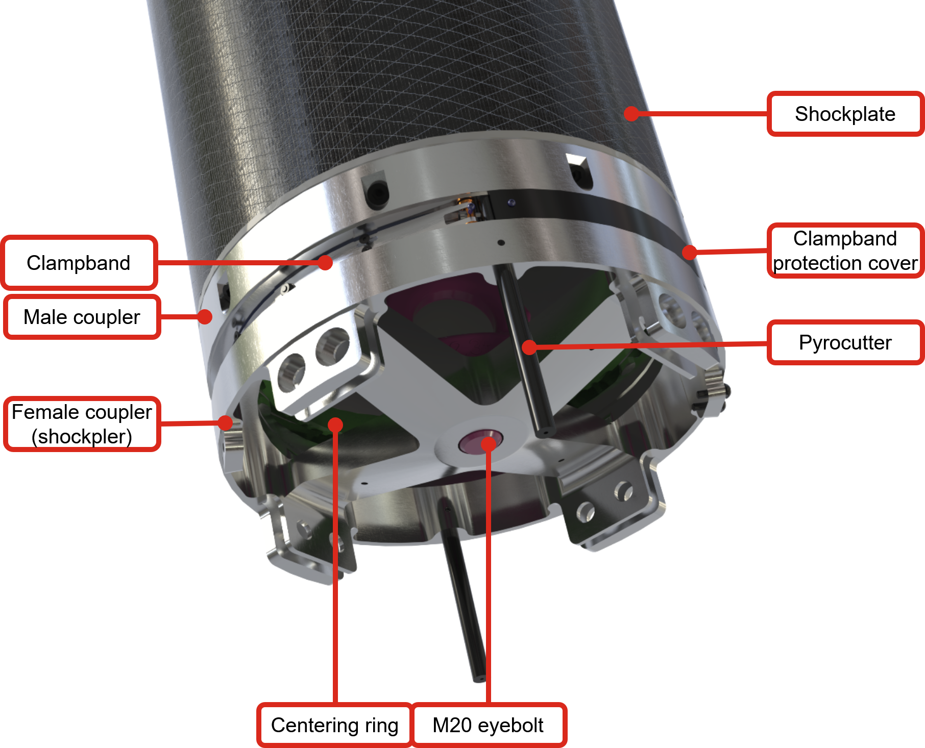
The lower interface of the recovery bay consists of an upper ring bonded to the tube and a male coupler, secured by a clamp band with two redundant separation mechanisms. Separation is triggered by e-matches igniting black powder charges in canisters. The resulting pressure propels a projectile that breaks screws and releases the rocket. The system requires up to 1 A and is powered by the avionics board operating on a 30 V bus.
For further information, see : 2024_C_ST_RE_LLIM
- 2024_C_ST_RE_LLIM Structure / Recovery Low Level Interface Management
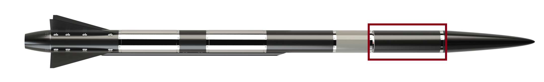
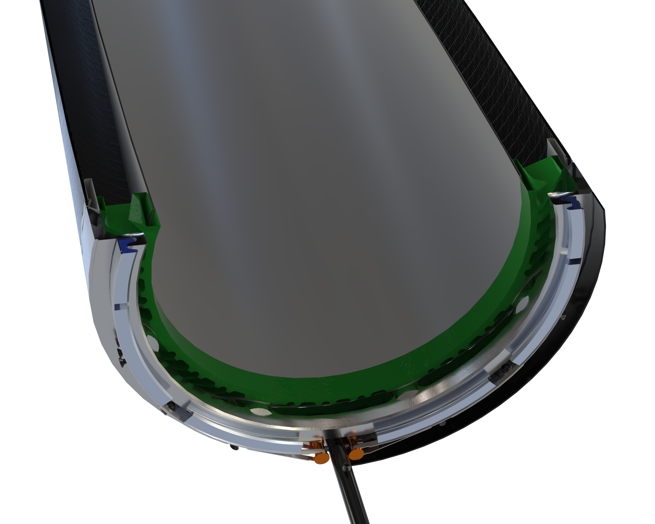
¶ Overview
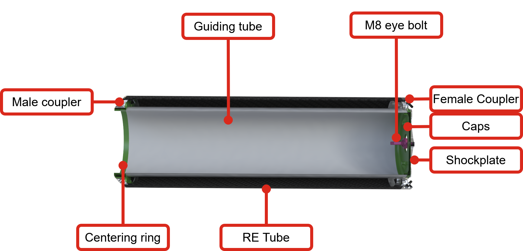
The recovery bay is built around a structural outer tube, with a female coupler bonded at the top and an upper ring bonded at the bottom. Inside, a centering ring supports the guiding tube radially, while the guiding tube itself forms the core of the assembly. It houses all recovery equipment, including the pilot parachute, the main parachute in its deployment bag, the shock cords, and the trigger boards used to unreef the main parachute.
At the bottom, the separation mechanism activates at apogee. Explosive charges inside a canister destroy two screws, loosening a clamp band that connects the male coupler (linked to the avionics bay and lower stage) to the upper ring (connected to the upper stage).
At the top, a shock plate with an eyebolt rests against the female coupler, while a 3D-printed cap separates the guiding tube contents from the rest of the rocket and ensures smooth separation.
¶ Parts Description
¶ 212202_Guiding_Tube
¶ Description
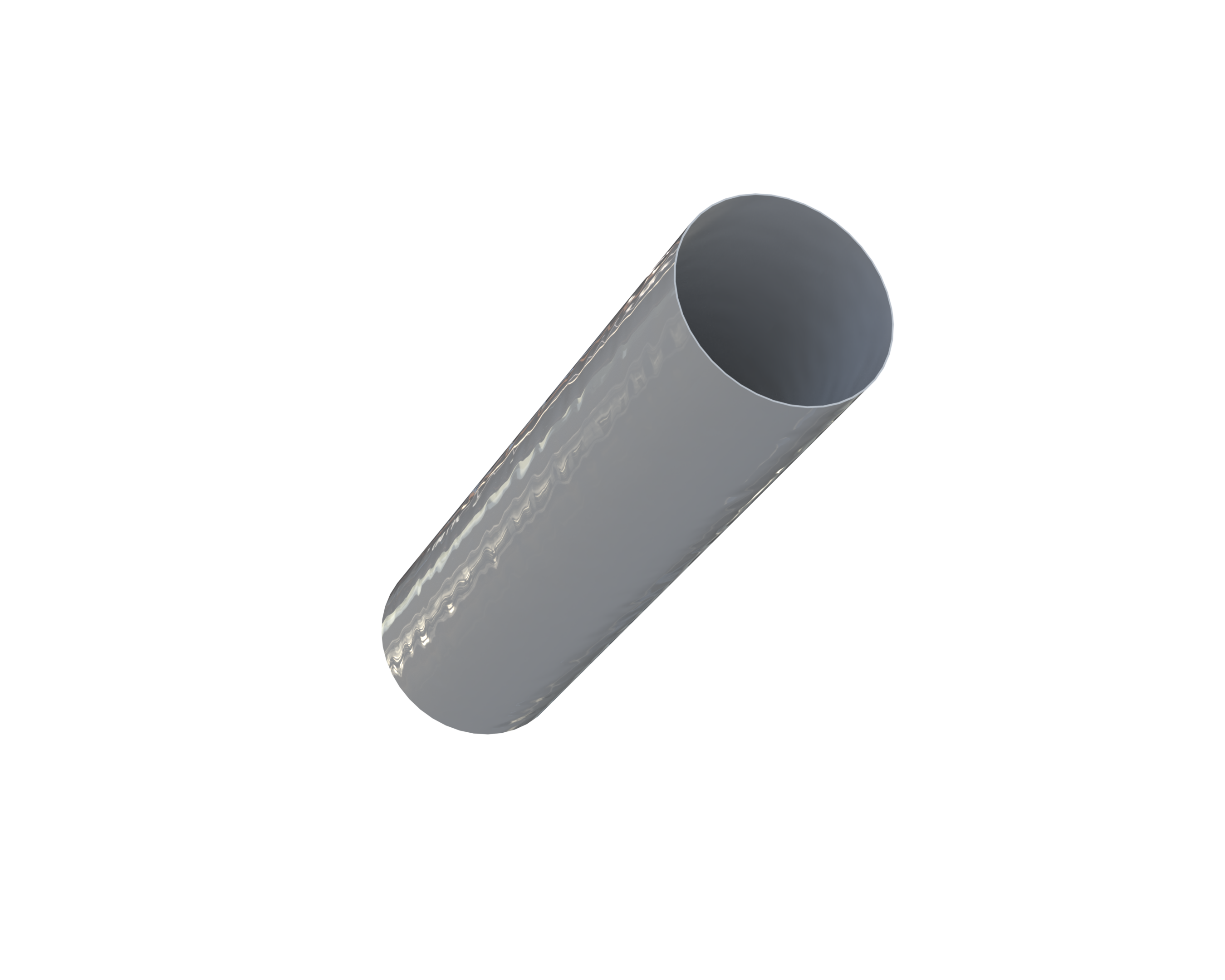
The guiding tube houses most of the recovery components, including the parachutes and shock cords.
¶ Main Specifications
| Specification | Value | Unit |
|---|---|---|
| Dimensions | 745 × 186 × 1 | mm |
| Mass | 1580 (TK, TBD) | g |
| Design Load (FoS included) | 4000 axial | N |
| Factor of Safety | 2 | – |
| Margin of Safety | 0.251 | – |
| Design Load | Non-structural components | N |
| Manufacturing | Wet layup on COTS aluminium tube | – |
| Cost | 150 | CHF |
¶ Interfaces
The guiding tube is held radially by a centering ring and axially at the top by being bonded to the caps, which are secured to the shock plate with four M4 screws.
¶ 213202_Shockplate_circular_M8
¶ Description
The shock plate, located at the top of the recovery bay, transmits the loads generated during parachute deployment to the rocket via its interface with the female coupler.
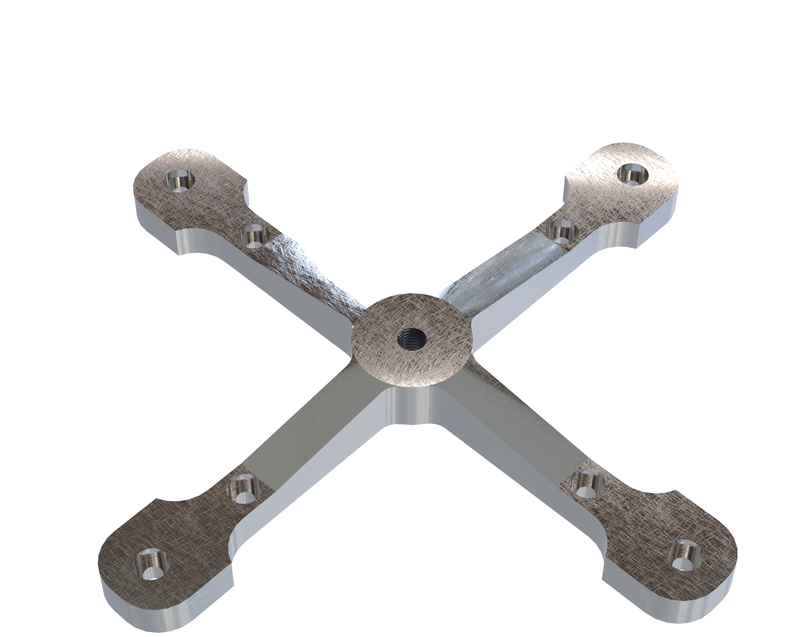
For more details on this component, see:
¶ 212203_Caps_V2
¶ Description
This component is bonded to the top of the guiding tube. Its main function is to isolate the guiding tube interior and its recovery components to ensure smooth deployment.
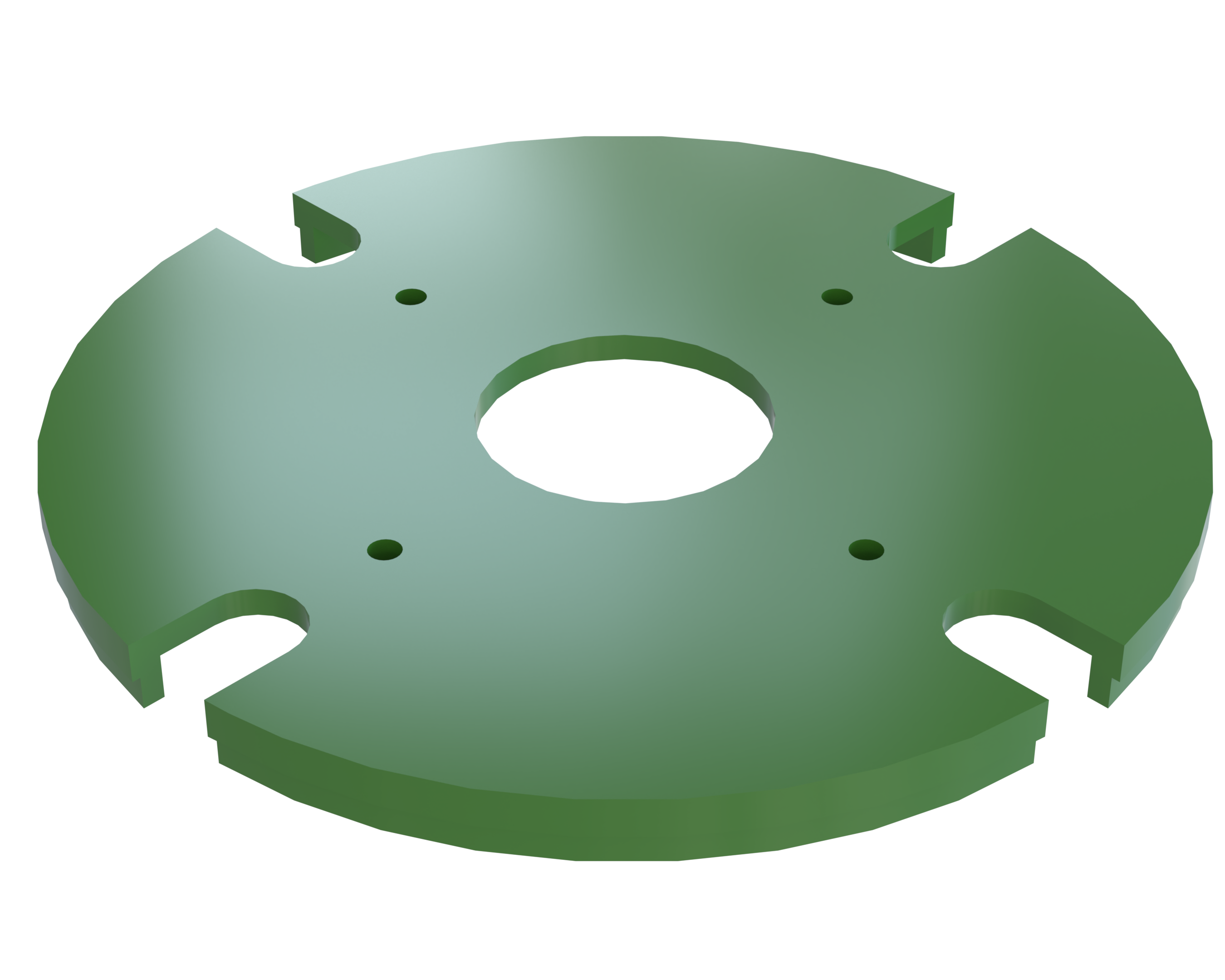
¶ Main Specifications
| Specification | Value | Unit |
|---|---|---|
| Dimensions | 187 mm diameter × 18 mm thickness | mm |
| Mass | 123 | g |
| Design Load | Negligible | N |
| Manufacturing | 3D-printed PET-CF | – |
| Fastening | M4 inserts | – |
| Cost | 30 | CHF |
¶ Interfaces
The cap is bonded to the guiding tube and interfaces with the female coupler on its upper side. It is secured with screws and contains four integrated M4 inserts.
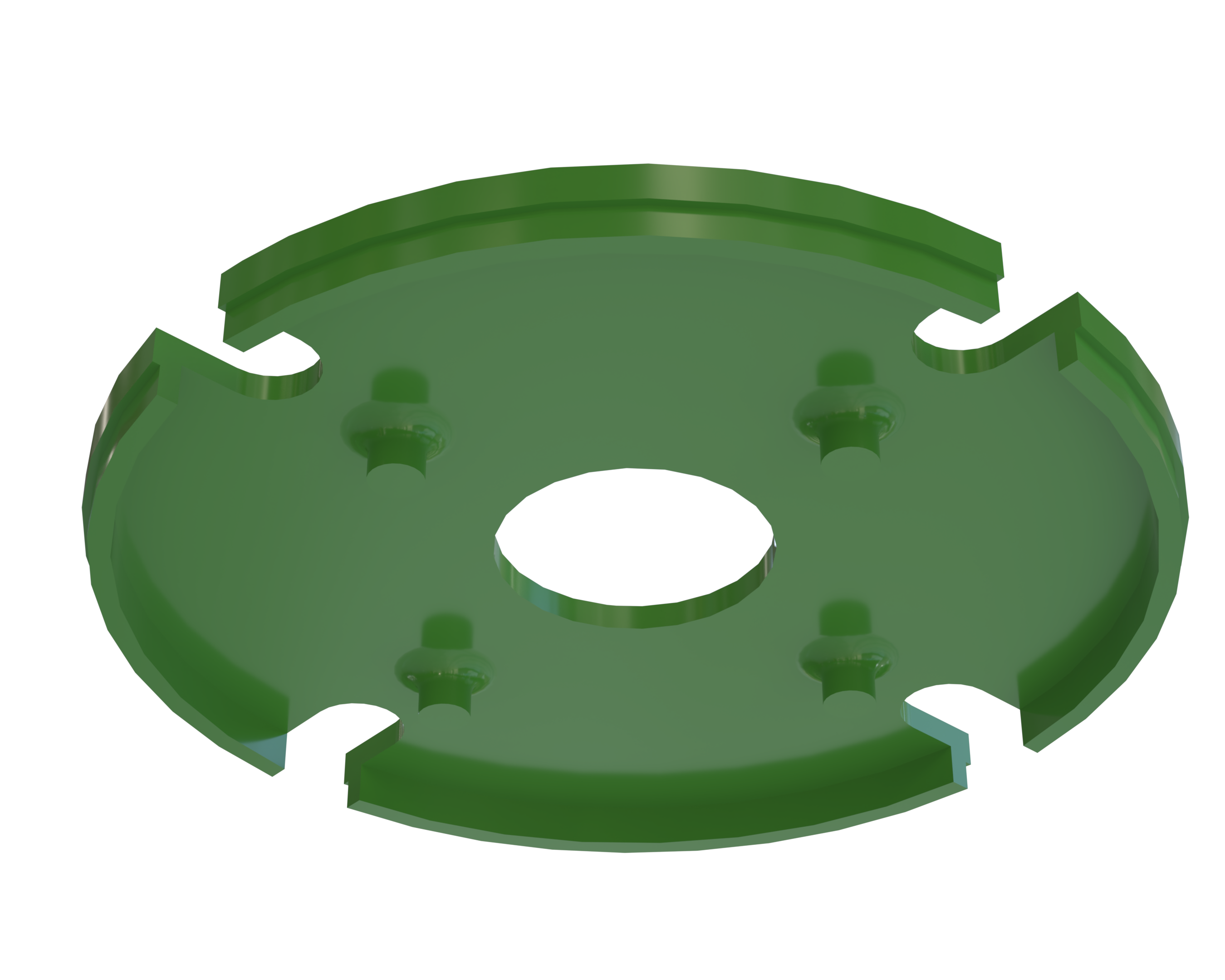
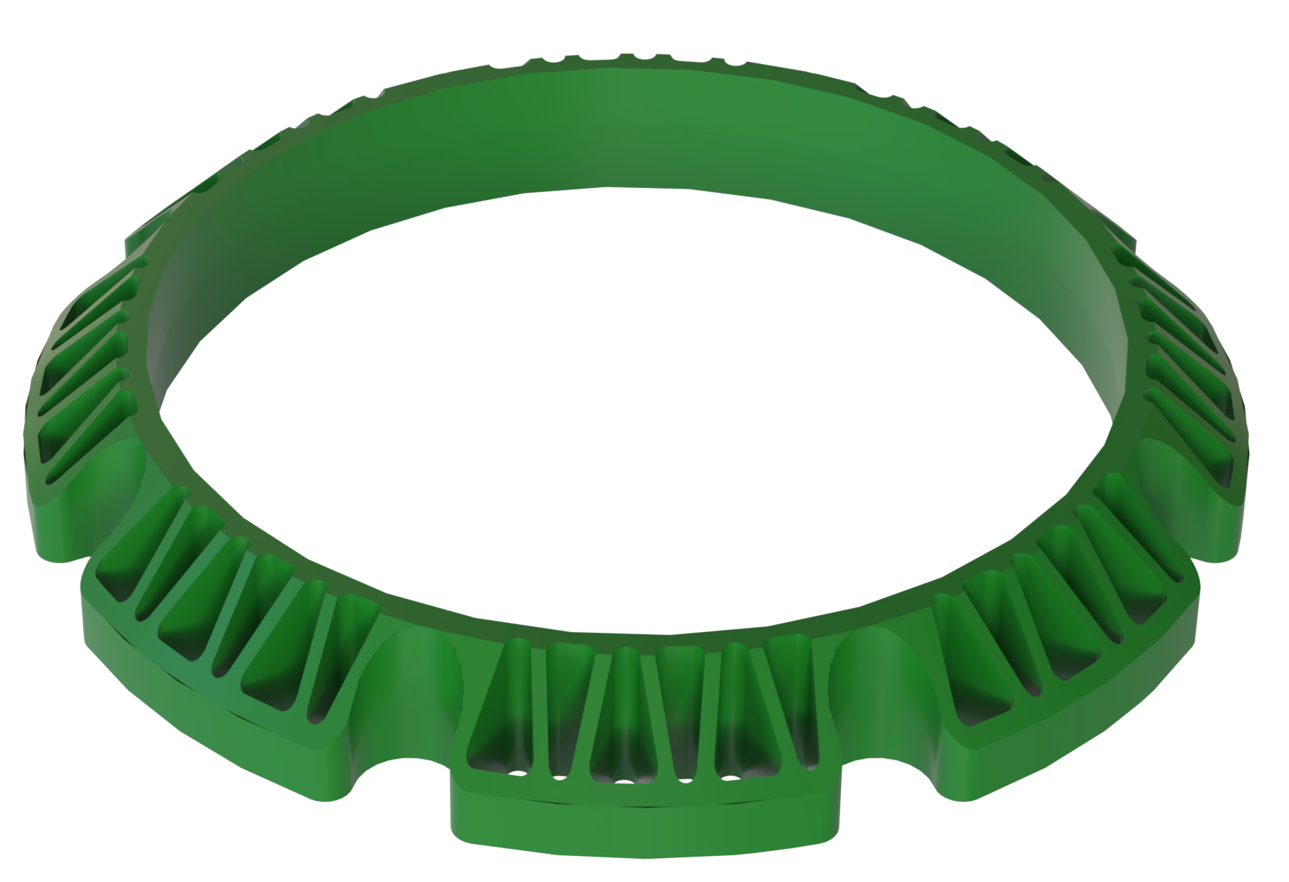
¶ 212204_Centering_rings
.png)
¶ Description
This component is bonded to the bottom of the guiding tube. Its primary function is to provide radial support to the guiding tube, while also reinforcing the assembly and protecting the shock cords from loads applied at the tube’s edge.
¶ Main Specifications
| Specification | Value | Unit |
|---|---|---|
| Dimensions | 30 mm thickness | mm |
| Mass | 213 | g |
| Design Load | No significant loads expected | N |
| Manufacturing | 3D-printed PET-CF | – |
| Fastening | Bonded | – |
| Cost | 30 | CHF |
¶ COTS Parts Table
| Part Name | Number of Parts | Main Characteristics | Link to Data Sheet |
|---|---|---|---|
| Eye Bolt | 1 | Meili M8 Eye Bolt | Eye Bolt |
¶ Eye Bolt
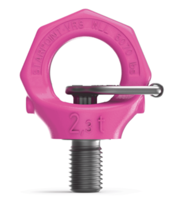
The eyebolt is mounted at the center of the threaded shock plate. During parachute deployment, following the activation of the separation mechanism, it is subjected to loads estimated as 30 g × the mass of the ejected upper section (including the entire recovery bay and payload bay inside the nose cone). A safety factor of 2 is applied.
The eyebolt acts as the interface between the two separated rocket stages:
- It connects to the upper stage via the threaded shock plate.
- It connects to the lower stage via the shock cord, which is attached to an M20 eyebolt (due to the higher lower-stage mass) secured to another shock plate.
For the FH9 configuration, a COTS M8 eyebolt has been selected with the following specifications:
- Capacity: 300 kg
- Factor of Safety (FoS): 4
- Allowable load: 300 × 9.81 × 4 = 11,700 N
Comparison with load cases:
- 11,700 N > 4,800 N (FH9)
- 11,700 N > 7,700 N (FH30)
This eyebolt is suitable for both FH9 and FH30 load cases, aligning with the team’s reusability-oriented design philosophy.
¶ Technical Budget, Margins and Deviation
| Type of value | Units | Requirement Value | Actual Value | Deviation |
|---|---|---|---|---|
| Dimensions | mm | Length: 600, Diameter: 243 | 243 × 600 | 0 % |
| Weight | kg | 6 | 5.28 | +16.7 % |
¶ Design Constraints
¶ Constraints for Production
One main production constraint is selecting tolerances for the centering rings. The objective is to achieve a radial fit tight enough to ensure stability while still allowing the guiding tube to slide in smoothly. Several uncertainties must be considered: once glued, the centering rings may not align perfectly.
To address this, the guiding tube will be sanded and measured to establish an average diameter. The centering rings will then be adjusted and 3D printed accordingly before being bonded inside the RE tube.
¶ Constraints for Operation
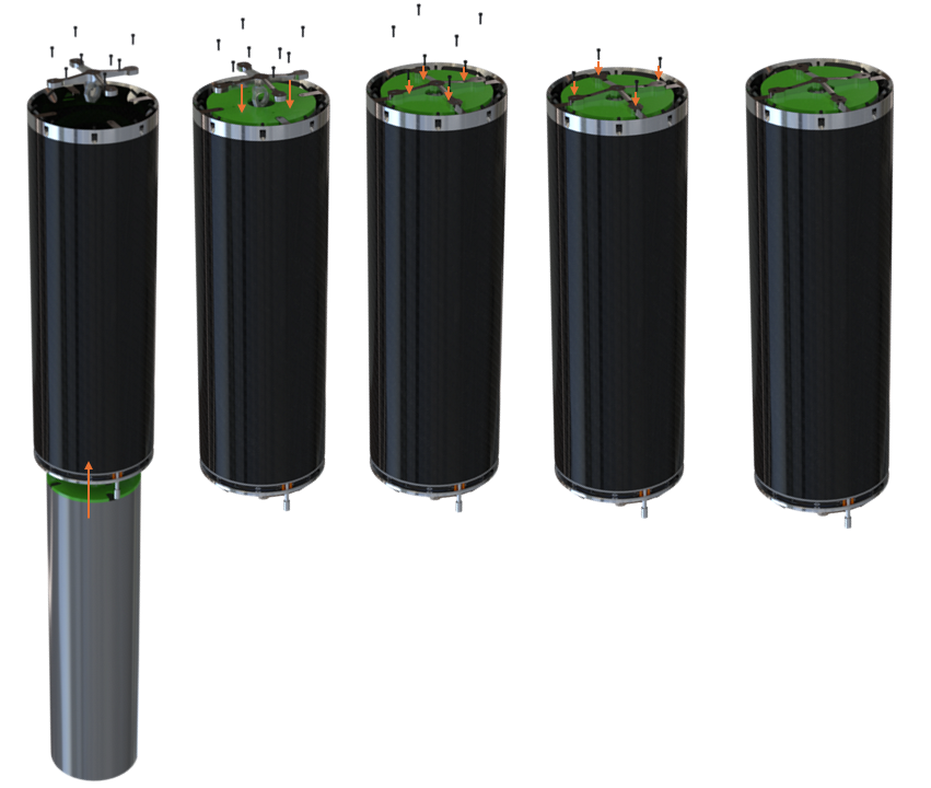
The only operational constraint concerns the order of assembly, shown in the diagram below. A detailed video is available here.
In summary, the guiding tube can only be inserted from the bottom.