¶ Introduction
¶ Purpose, Objective and Scope
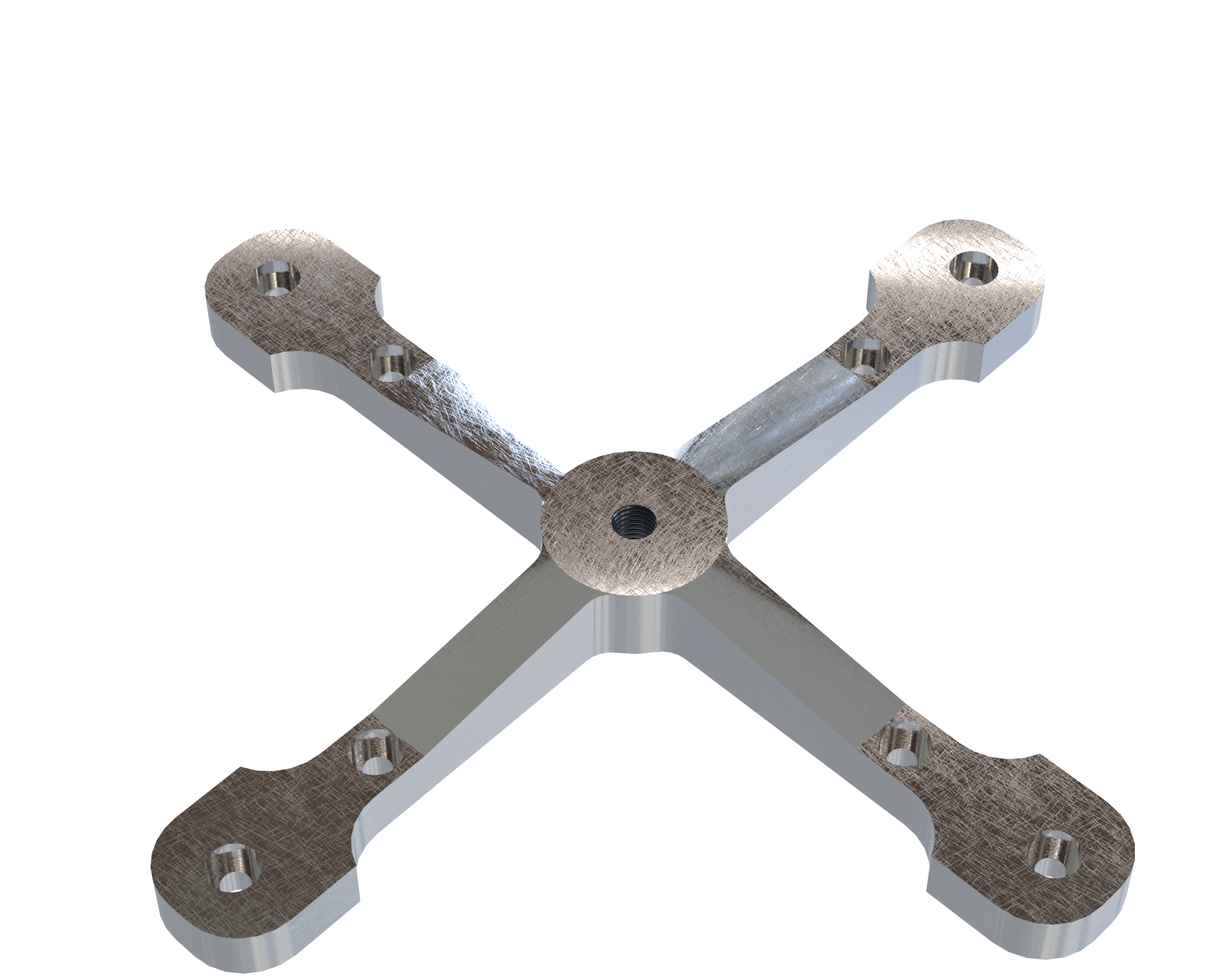
This document presents the design and the engineering process behind the conception of the shock plate of the recovery bay for the Firehorn rocket.
¶ Definitions and Abbreviations
- RE: Recovery
- REB: Recovery Bay
- AVB: Avionics Bays
- SM: Separation Mechanism
¶ Applicable and Reference Documents
- 2024_C_ST_RECOVERY-BAY_DDF
- 2024_C_ST_SHOCKPLATE_DDF
- 2025_C_ST_Shockplate_FEA
- 2024_C_ST_RE_LLIM
- 2024_C_ST_SEPARATION_MECHANISM_DDF
- 2024_C_ST_SEPARATION_MECHANISM_TSP
- 2024_C_ST_COUPLERS_DDF
- 2025_C_ST_RECOVERY-BAY_PURPOSE_IR
- 2025_C_ST_RECOVERY_BAY_MAP
¶ Requirements
The shockplate must meet and comply with the following requirements:
- 2024_C_SE_ST_RECOVERY-BAY_REQ_01
Declaration of purpose
The recovery bay shall host the RE systems of the LV.
This requirement has been verified in the following document.
 2024_C_ST_RECOVERY-BAY_DDF
- 2024_C_SE_ST_RECOVERY-BAY_REQ_13
Upper shockplate load case
The structural elements in the recovery bay of the FH I LV shall withstand [4800]N of axial tensile loads.
The shockplate verifies this load requirement with a MoS of 0.82. This is indeed above the general requirement of a MoS > 0.15.
This requirement has been verified in these documents.
¶ Overview
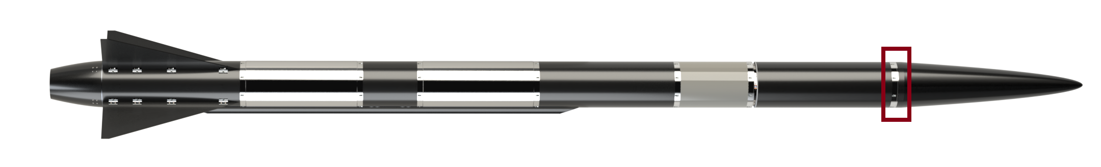
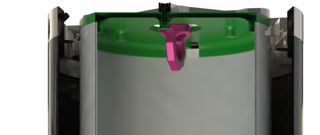
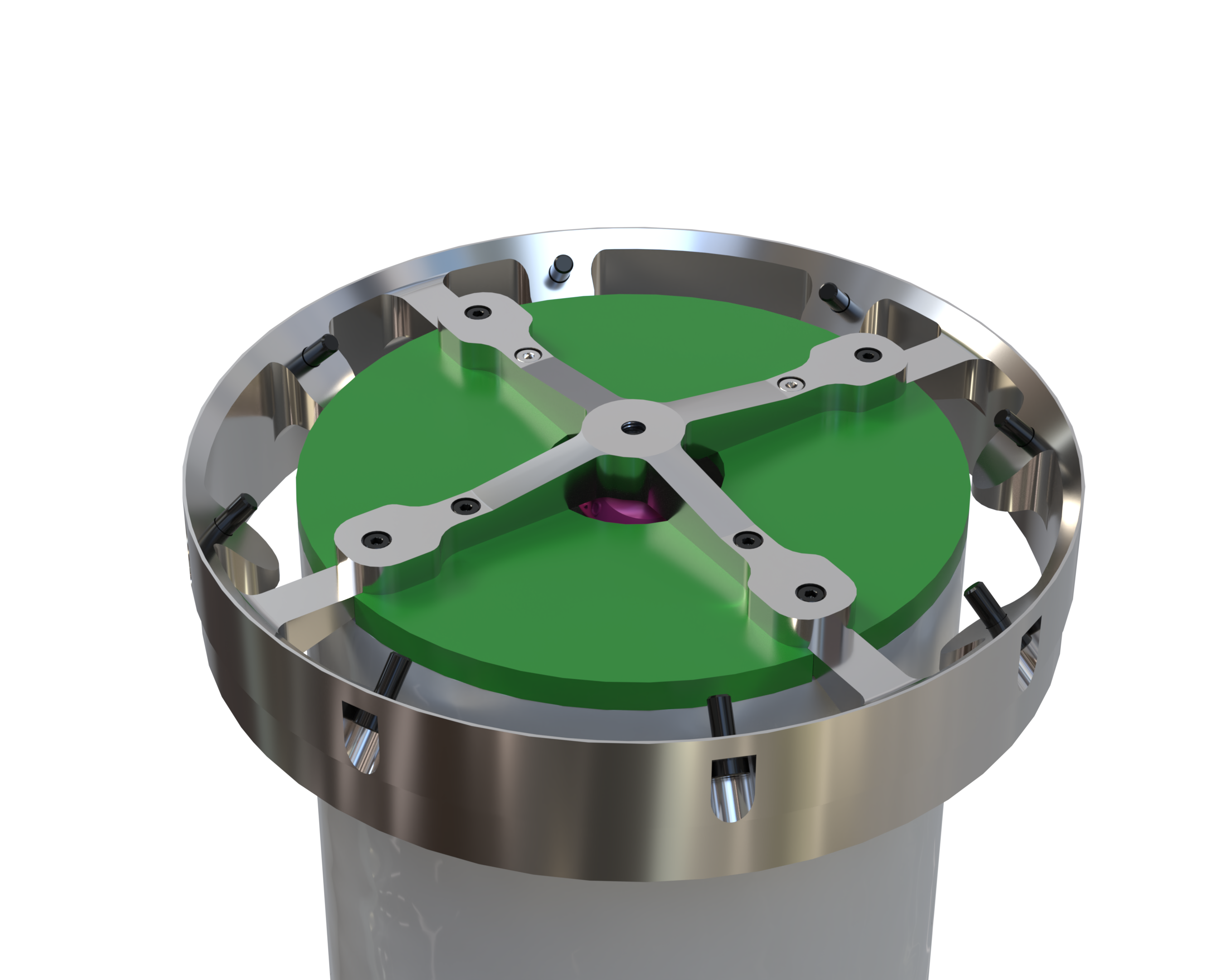
At apogee, the rocket separates into two parts using the Separation Mechanism (SM) to deploy the parachute. Both parts of the rocket the Nosecone Bay and Recovery Bay, and the remaining Launch Vehicle are connected to the parachute via shock plates. The role of the shock plates is to absorb and transmit the forces generated during parachute deployment.
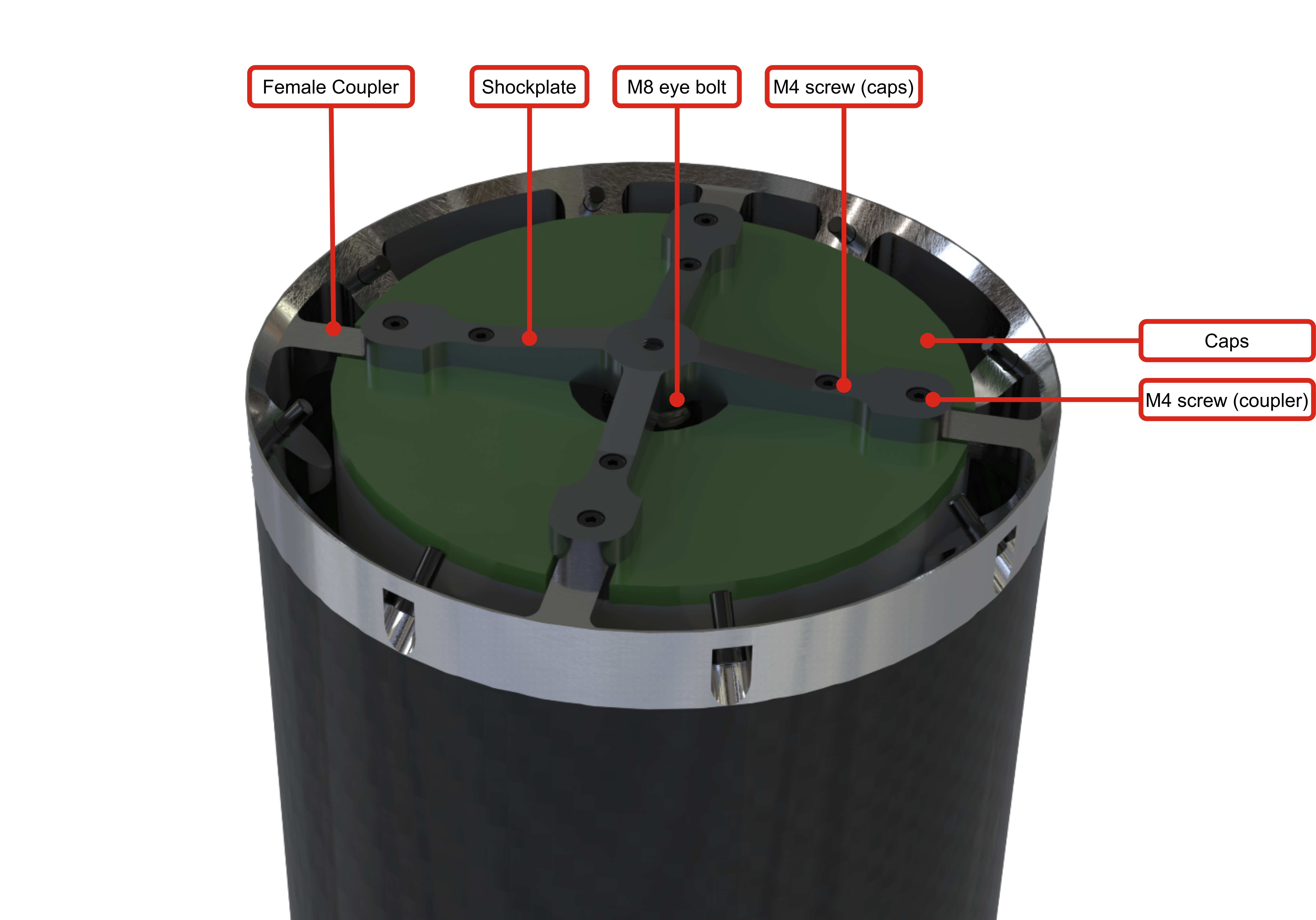
The shock plate, positioned at the top of the recovery bay, primarily transmits these forces to the rocket structure through its interface with the female coupler.
Its main role is to withstand the axial load of 4800 N (for FH9), corresponding to the effective load of the rocket’s upper section under a deceleration of 30 g, including a safety margin.
For the FH9 configuration, this corresponds to a dry mass of 8 kg experiencing 30 g of deceleration, with a factor of safety (FoS) of 2 applied.
F = 8 kg * 30 g * 2 = 4800 [N]
¶ Main Specifications
| Specification | Value | Unit |
|---|---|---|
| Dimensions | Diameter: 180; thickness: 14 at the center, 9 at the branches | [mm] |
| Mass | 134 | [g] |
| Design Load (FoS) | 4800 Axial (FH9) | [N] |
| Factor of Safety | 2 | |
| Margin of Safety | 0.82 | |
| Manufacturing | 5-axis CNC, sanding | |
| Fastening | 8 M4x15 Hex bolts | |
| Cost | 200 | [CHF] |
¶ Analysis and Simulations
The shock plate was initially designed and optimized for the FH30 load case. It could also be adapted for FH9, but since the current weight is already quite low, the same design has been retained.
¶ Load case of FH30
Load : 30g x 9.81 x 13.2kg x 2FoS = 7.77kN.
The 13.2 kg represents the total mass supported by the shock plate, including its own weight, the male and female couplers, the payload, and the nose cone.
¶ Load case of FH9
Load : 30g x 9.81 x 8kg x 2FoS = 4.8kN.
The 8 kg represents the total supported mass for FH9, including the same components as above.
- 2025_C_ST_Shockplate_FEA Shockplate Finite Element Analysis Report
¶ Technical Drawings
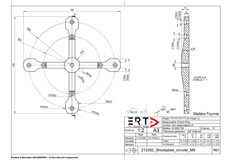
¶ Interfaces
For more information, refer to the ST_RE_LLIM linked here 2024_C_ST_RE_LLIM.
¶ Design Constraints
¶ Constraints for Production
The shock plate must be manufactured using a 5-axis CNC machine. The recommended material is AL2050 T84, a strong and lightweight aluminum alloy.
¶ Constraints for Operation
Using a nut to hold the eye bolt was not possible due to the plate’s thickness. Instead, the shock plate was threaded and fitted with a helicoil to secure the bolt.