¶ Introduction
The objective of the design justification file (DJF) is to present the rationale for the selection of the design solution, and to demonstrate that the design meets the baseline requirements.
This document presents potential new designs for the Anti Buckling Rings (ABRs), through a State of the Art analysis.
ABRs are a key part of the rocket's internal structure, serving as a protection against the rod's buckling, an attachment position for Modular Part Systems (MPS), and - potentially - a support for the tanks.
The ABRs are located within the pressurant bay, engine bay, and avionics bay - the quantity of ABRs will not be the same in each bay.
¶ Definitions and Abbreviations
- DJF : Design Justification File.
- ABR: Anti Buckling Ring, the design presented in this document, a "ring" to protect against buckling
- FoS: Factor of Security
- FH: Firehorn - Launch Vehicle designed for 9km
- FH30: Firehorn 2 - Launch vehicle (for 30km)
- CFRP: Carbon Fiber Reinforced Polymer
- FEA: Finite Element Analysis
- MPS: Modular Part System
- ST: Structure (Sub System)
¶ Relevant Knowledge Needed
Anti Buckling Rings are a specific design that appears in 3 separate bays of the launch vehicle, and serve the same purpose in each one. In order to dimension them properly, they follow a specific set of requirements.
In addition, they depend on the rest of the internal structure, and the tanks.
Here, we detail some of these requirements and link to past work.
Engineering Requirements
- Compatible for the 9km and 30km versions of the rocket.
- Resists the flight loads (buckling due to internal structure compression)
- Capable of mounting and supporting MPS (Modularity)
- Low Impact on Accessibility
- 2024_C_SE_ST_REQ_08 LV inside diameter
The LV shall have an internal diameter of maximum [240]mm. - 2024_C_SE_ST_INTERNAL-STRUCTURE_REQ_05 Axial compression
The internal structure shall withstand [15000]N of compression without failure. - 2024_C_SE_ST_INTERNAL-STRUCTURE_REQ_06 Buckling
The internal structure shall withstand [15000]N of compression without loss of stability (buckling).
These 4 links are the "most important" documents related to ABRs in the documentation uptil now - by navigating into Firehorn > Structure > Internal Structure, more documentation can be found, including testing procedures, reports and more FEA.
- Internal Structure DJF: 2024_C_ST_INTERNAL-STRUCTURE_DJF
- Internal Structure DDF: 2024_C_ST_INTERNAL-STRUCTURE_DDF
- Buckling FEA: 2024_C_ST_MODULE_FEA
- Non Linear Buckling FEA: 2024_C_ST_NON_LINEAR_BUCKLING_MODULE_FEA
¶ State of the Art
We started by looking at what other teams were using in their internal structure. However we soon found that the Rocket Team's approach was quite unique and we couldn't find a similar approach anywhere else. Some teams use the external carbon tube as the main structure for example.
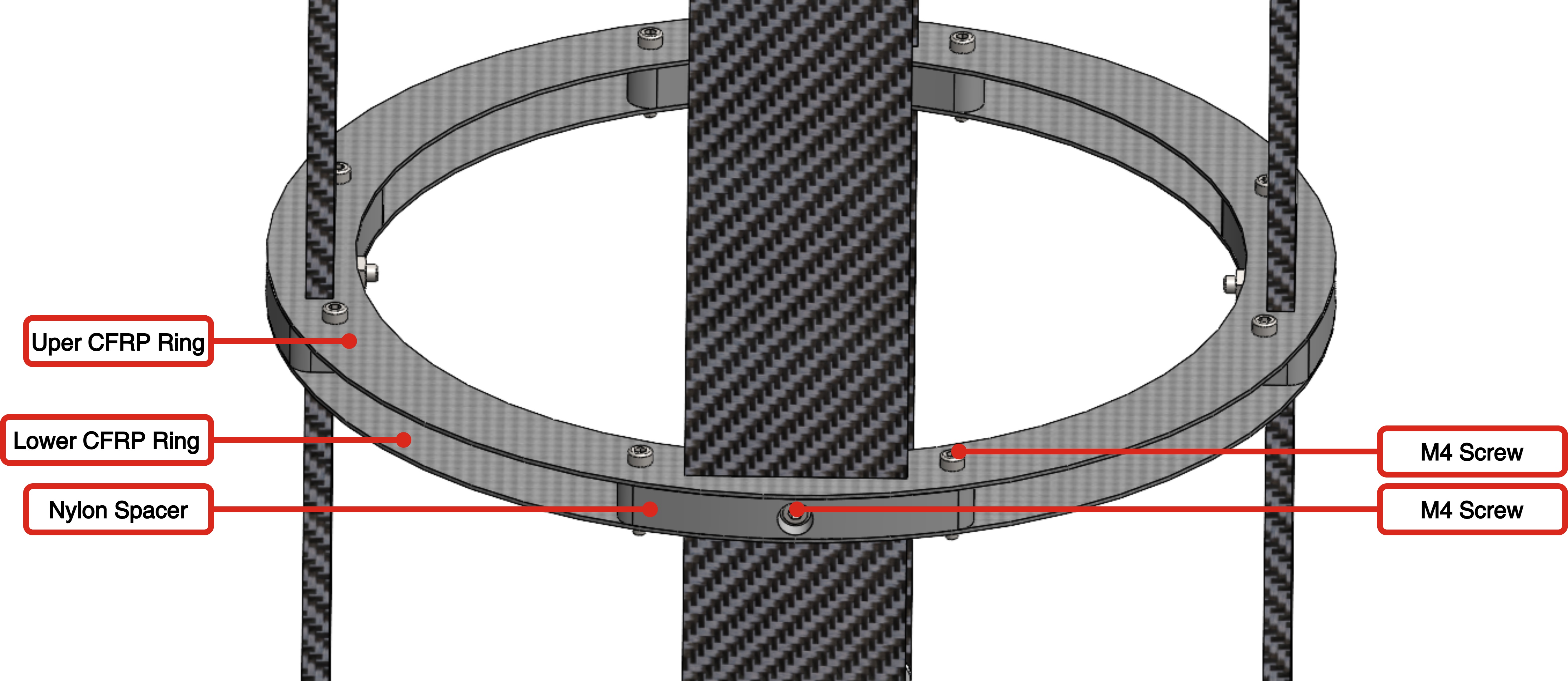
We then looked at past work from the team and in particular the previous semester project on the aluminium ABRs done by Florent Piton and Vianney Jacob. Their report ends with a design proposition for composite ABRs consisting of two carbon rings separated vertically by nylon spacers. This design allows ease of access and space for the MPS while introducing the idea of composite materials in the design of the ABRs.
Looking at general information on how to reduce the effects of buckling. We found no such thing as an "anti-buckling ring" but general tips on beam thickness, geometry and materials. Since the rods are a constraint for our project, we couldn't explore these tips.
However, we also found some information on beam reinforcement, namely one paper talked about a metallic cage like structure going all along the beam in an effort of increasing srtuctural rigidity.
Finally, looking into composite manufacturing (limiting ourselves to what could be done at EPFL or with the help of companies close to the Rocket Team), we looked up information on pre-preg manufacturing, carbon infusion manufacturing and carbon 3D printing (thanks to TCDC) which would have allowed us perfect control of fiber orientation.
¶ Geometry Propositions
These geometry propositions are the original ideas for what shape the rings can take. They are organized in two "subsets" - seen from above, and seen from the side (a profile view), each "profile view" can be applied to the "top" view and vice-versa, allowing for multiple combinations.
Many of the explanations here are assumptions, and the decisions between these shapes will be executed based on FEA analysis.
The primary logic for the top view was to have a circular shape, as it should provide the most continuous shape, limiting the concentration of forces in any particular place - however, given previous iterations of ABRs where an octagonal shape yielded the best results, we decided to explore the obvious circular shape, the octagonal shape, and a dodecagon, an intermediary choice between circle and octagon.
¶ Circle
The most continuous shape, although it generates discontinuities around the rod insertions.
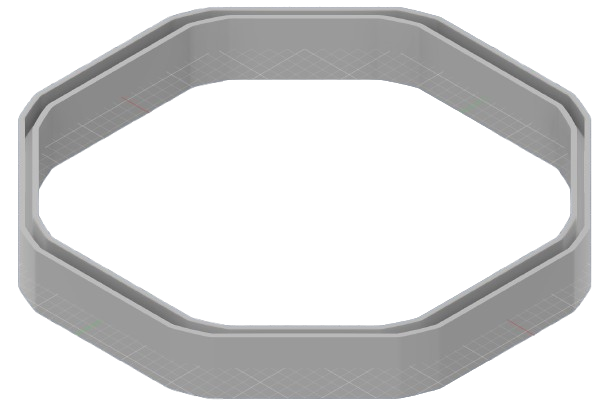
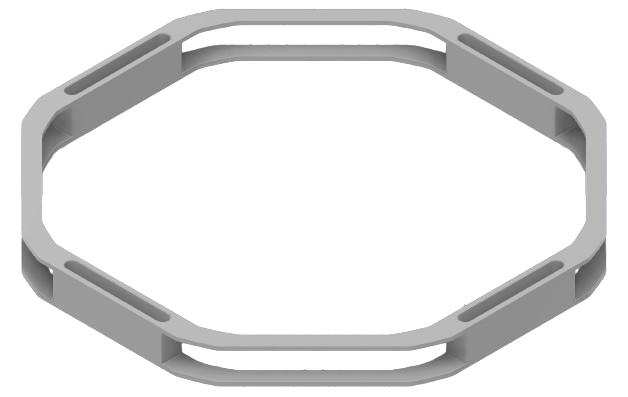
¶ Octagon
This shape comes from the previous iterations, having found it to be better suited than the circle. We assume the "parallel" shape around the rods may be better in order to avoid concentrating forces around the rods.
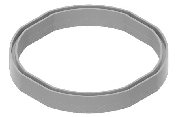
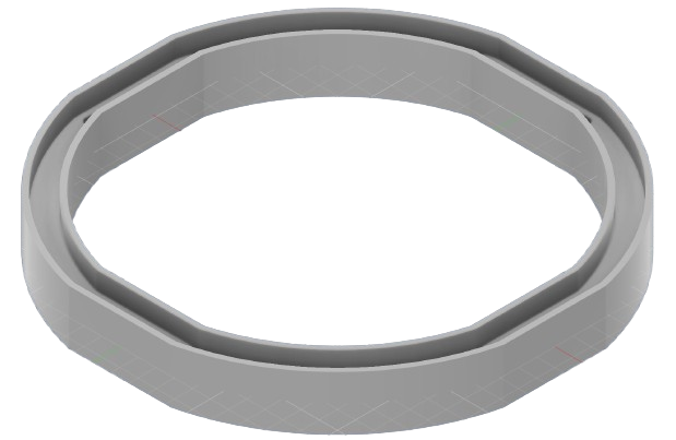
¶ Dodecagon
Based on the assumption that we want to avoid concentrating constraints around the rods, the dodecagon keeps that "advantage" from the octagon, while having more segments, getting "closer" to a circular shape.
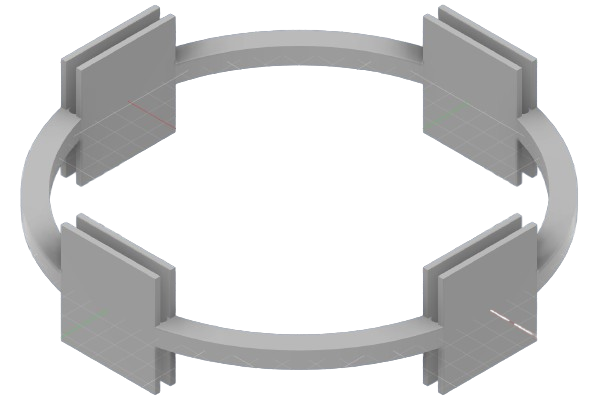
¶ "Spacer" Design
This design was not considered in a previous iterations due to time constraints, so we are picking it back up again. As seen in the diagram, it acts as two CFRP rings spread apart by two spacers.
With this design, we can consider having 4 rings total (two concentric rings, one outer, one inner, for the upper and bottom one), we can also modify the heigh of the spacer, and toy with the ring's thickness and diameters.
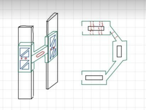
Another approach to the "top view" of this geometry is to have a slightly more "rectangular" part in contact with the rods, as seen in this drawing:
¶ "I Beam" Designs
I beams are often used in structural design, mostly to resist flexion, by putting the mass further from the center of mass and increasing the inertia. We have two "I-Beam" inspired designs, a vertical, and horizontal I.
Both designs could be compared to the spacer design.
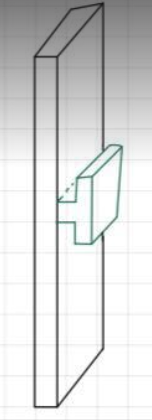
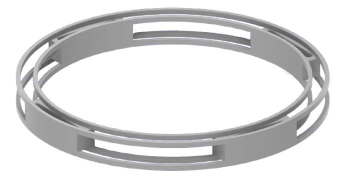
¶ Vertical
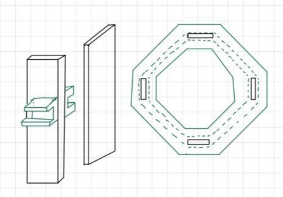
This design, in a sense, is very similar to the spacer design, but the spacers follow the entire perimeter of the ring, and holes would be placed in the thinner part of the beam to attach different MPS. The "top" view could be used with every proposition described above.
The advantage is that we have a tall "support" applied by the ABR on the rods themselves, and the wider parts of the I have a longer vertical spacing, increasing the distance on which the rod is effectively "clamped."
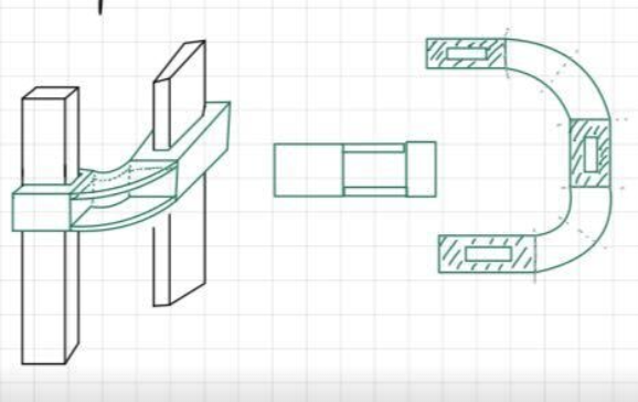
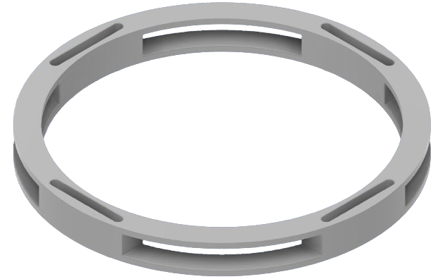
¶ Horizontal
This design follows that found in a commercial design used to fight against buckling on a cylinder, from, as per the documentation, external pressure.
The core design principle was to maximize moment of inertia by bringing "as much area as possible in a section far from the reference axis," thus, putting the I such that most of the ring is further away from the rods themselves.
This of course, is only so possible in the extent that there is a maximal diameter of the launch vehicle anyways.
¶ "Increased Contact Area Design"
The core principle for this design is that buckling occurs when a rod is thin and long - the longer unsupported length a rod has, the more it will be prone to buckling. Equally, having a higher moment of inertia increases the critical load at which buckling starts.
By having an increase contact area around the rods, we increase the "supported length" of rod, which is either no longer or less susceptible to buckling (as their moment of inertia will equally be bigger than that of the rod). If it effectively acts a clamp, one ring would "split" the length prone to buckling into two.
The blue triangles represent places where we could gain in mass, as the increased height doesn't need to be "full." The idea comes from this document, where a "grille" is used to prevent buckling (completely different design situation, but the grille was interesting)
https://www.mdpi.com/2226-4310/10/5/484
This document describes some of the inspiration of this design, where an I can be used instead of the triangle cut outs, but the idea is to increase the supported length of the piece under buckling.
https://www.instron.com/en/products/testing-accessories/composite-test-fixtures/
¶ Material Considerations
Carbon Fiber Reinforced Polymer (CFRP) excels in structural design thanks to its strength-to-weight ratio (E/ρ) and high stiffness. CFRP's particularity, the orientation of fibers, is both a blessing and a curse. While it allows you to optimize a design by orienting the fibers as a function of the load case, maximizing its potential, CFRP components have more limited use for load cases for which they are not designed for, involving multiple axes: this is the trade off between anisotropy and isotropy.
Another important consideration here is the manufacturing time - at the Rocket Team composite parts are often made by the students, which means there is a non neglibile amount of time required to learn the process, and then execute it properly.
Among accessible composites for the Rocket Team, (so, for example, excluding alumina due to its high cost) CFRP is an "obvious choice," as its material properties are excellent, it is not excessively expensive, and we already have in house experience on manufacturing and designing parts in carbon fiber.
CFRP provides different techniques for manufacturing, most notably infusion and prepreg (as well as 3D printing). While 3D printing would have been a very interesting technique to optimize fiber orientation, opening the possibilities towards new designs, we unfortunately did not have access to such infrastructure in the scope of our project. Between infusion and prepreg, we chose prepreg as it allowed us to have an easier, more repeatable process for manufacturing - which two of us had already been a part of at APCO. It also the choice that the Rocket Team made for its tubes earlier on, and the designs we decided to manufacture were, essentially, tubes.
Aluminum is an excellent material, equally thanks to its strength-to-weight ratio and stiffness, although its maximum Young's Modulus is lower than CFRP's maximum. As an isotropic material, it is easier to design and facilitates manufacturing, as there are fewer necessary considerations as to how to manufacture the piece, and even how to design it.
From a manufacturing point of view, the usage of workshops like l'ATME mean we are trading budget for time, where students don't need to learn or spend time perfecting the manufacturing process, but we have to allocate budget to this.
Although aluminum is an excellent material choice thanks to its properties and time effectiveness, the objective of this project is to see if its possible to utilize composite's particular properties to optimize the past ABR designs. As such, that is what we will be focusing on.
Added later into the design, PETCF is our final choice for the "spacers" used in our designs.
PETCF's notable advantage is split in two:
- Material properties: compared to other 3D printed components, the Carbon Fiber addition offers improved strength and stiffness, keeping a relatively low weight.
- 3D Printability: PETCF is notably easier to 3D print than other materials such as NYLON CF, thanks to its lower moisture absorption, as well as having improved bed adhesion with decreased warping.
3D Printability was quite important for the spacers as we wanted easily iterable designs with high flexibility on the shape, which, given the DLL's 3D printing infrastructure, was most accessible with 3D printers.
¶ First CAD designs
The different designs were translated into CAD files to be incorporated into assemblies. Because of new talks concerning manufacturability and a possible partnership with TCDC which would offer us the possibility to "3D print" our designs, we were capable of producing more advanced geometries.
We chose to move to the simulation phase with the following designs which can be grouped into three families :
"H ABR"
"Large H ABR"
"Octagonal H ABR"
"Concentric Rings ABR"
"Spaced Rings ABR"
"Octagonal Spaced Rings ABR"
"High Spacers ABR"
¶ Simulations
At first, we tried finding the forces acting on the ABRs themselves from the assembly simulations of the previous design. The process is described in the following document : 2025_C_ST_PDB_NON_LINEAR_BUCKLING_MODULE_TRANSMITTED_FORCES_FEA.
In short, we ran non-linear simulations on an assembly consisting of four long CFRP rods with an aluminium coupler on each end of the rods and two aluminium ABRs of the previous design.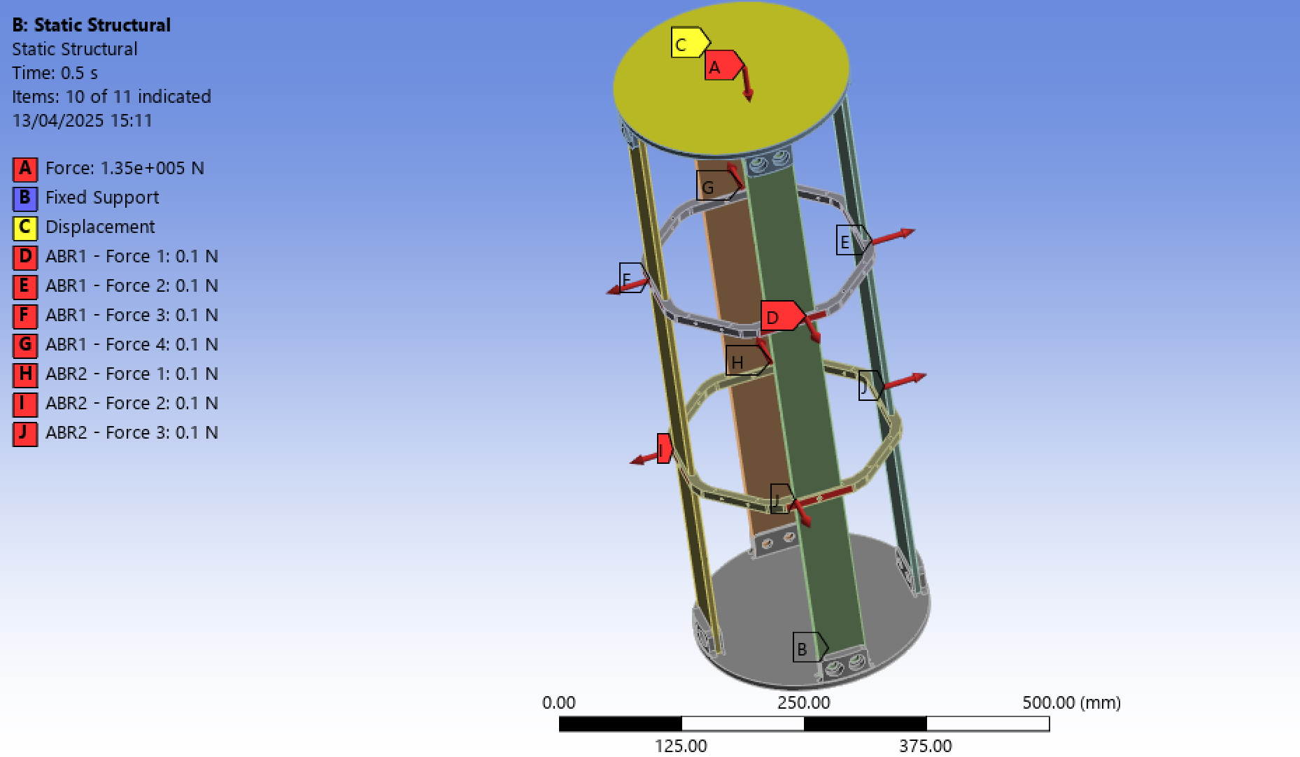
However, this simulation did not yield consistent results and it was decided that simulating the entire assembly with different rings each time would be simpler and more accurate then trying to understand why we were getting the poor results. Furthermore, this meant that we could use the methodology that the team had been using for the previous full assembly simulations for our own simulations.