¶ 2024_C_ST_TANKS-2195_FEA
This document aims to present the method used to analyse with finite elements software the tank of the Firehorn rocket. Indeed, this assembly is subjected to various loads during the flight, and it must be as light as possible to improve the rocket's performances.
¶ Geometry
The tank is composed of a main cylindrical section, manufactured in aluminium 2195 T-84. Moreover, to close the tank, and to host the 8 different exits and entries, 2 end-caps are welded to both ends of the cylinder.
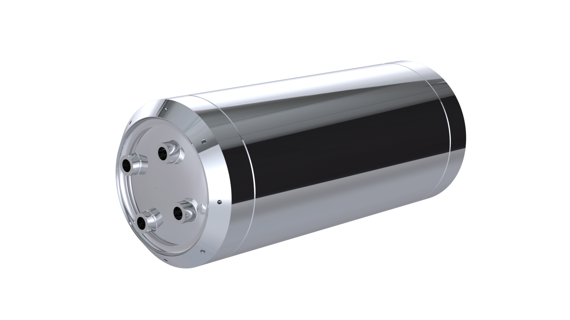
The version used for these FEA simulations is a tank with a 26 [L] capacity. This volume has been estimated as the maximum volume of propelants needed for the flight of Firehorn to 9 [km].
¶ Function
The tanks are necessary to host the propellants for the rocket to ignite and use its bi-liquid engine. Therefore, for the Firehorn projet, the tanks will be filled with ethanol and liquid oxygen. The tank also have a structural role, and they shall be able to withstand all flights load, as well as the nominal operating pressure of the plumbing system (60 [bar]).
¶ Material
¶ Cylindrical section
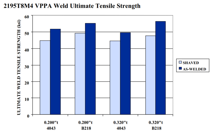
The main part of the tank is made of a rolled sheet of aluminium alloy 2195-T8. This sheet is then welded in the longitudinal direction to form a closed cylindrical section. The properties of the alloy are listed below:
Being welded, we need to account for the loss of mechanical properties. Therefore, based on the data from NASA tests, we will take a value of 345 Mpa for the tensile strength for this alloy.
We will moreover need more information from our aluminium supplier to be sure these datas are accurate.
¶ Caps
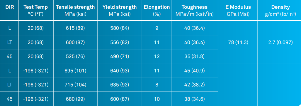
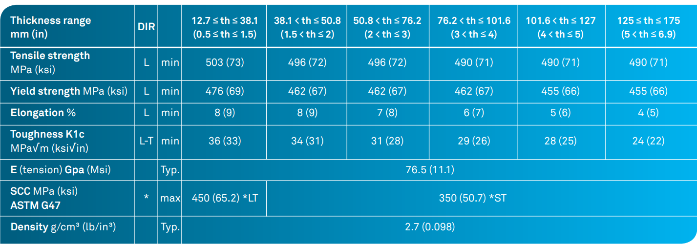
The end-caps are machined in 2050-T84 alloy. This alloy has the following properties:
¶ Load case
Being highly pressurized (60 [bar] at nominal pressure), the main load responsible for high constraints in the assembly will be the internal pressure. However, the requirements impose to design a tank capable of withstanding 120 [bar] without catastrophic failure (i.e. no constraint above the tensile strength), and 90 [bar] without any constraint above the yield strength. Moreover, the pressure might induce a certain buckling.
- 2024_C_SE_ST_TANK_REQ_02 Tank structural role
The tank shall bear all the flight and pressure loads on their own. - 2024_C_SE_ST_TANK_REQ_09 Tank yield pressure
The tank shall not yield under an internal pressure of [90]bars for [120] minutes. - 2024_C_SE_ST_TANK_REQ_26 Tank burst pressure
The tank shall not burst under an internal pressure of [120]bars. - 2024_C_SE_ST_REQ_38 Load Case - FHI Compression
The FH I LV shall resist compression induced by a compression force of [10000]N instead of [15000]N.
¶ Parts List
The assembly is composed of 3 parts (2 end-caps and 1 main cylindrical section). In real life, the parts are welded together with MGAW or VPPAW. However, simulating with FEM this types of interactions is very complex and often not realistic. That's why we decided to merge all the three parts, and analyse the welds lines later.
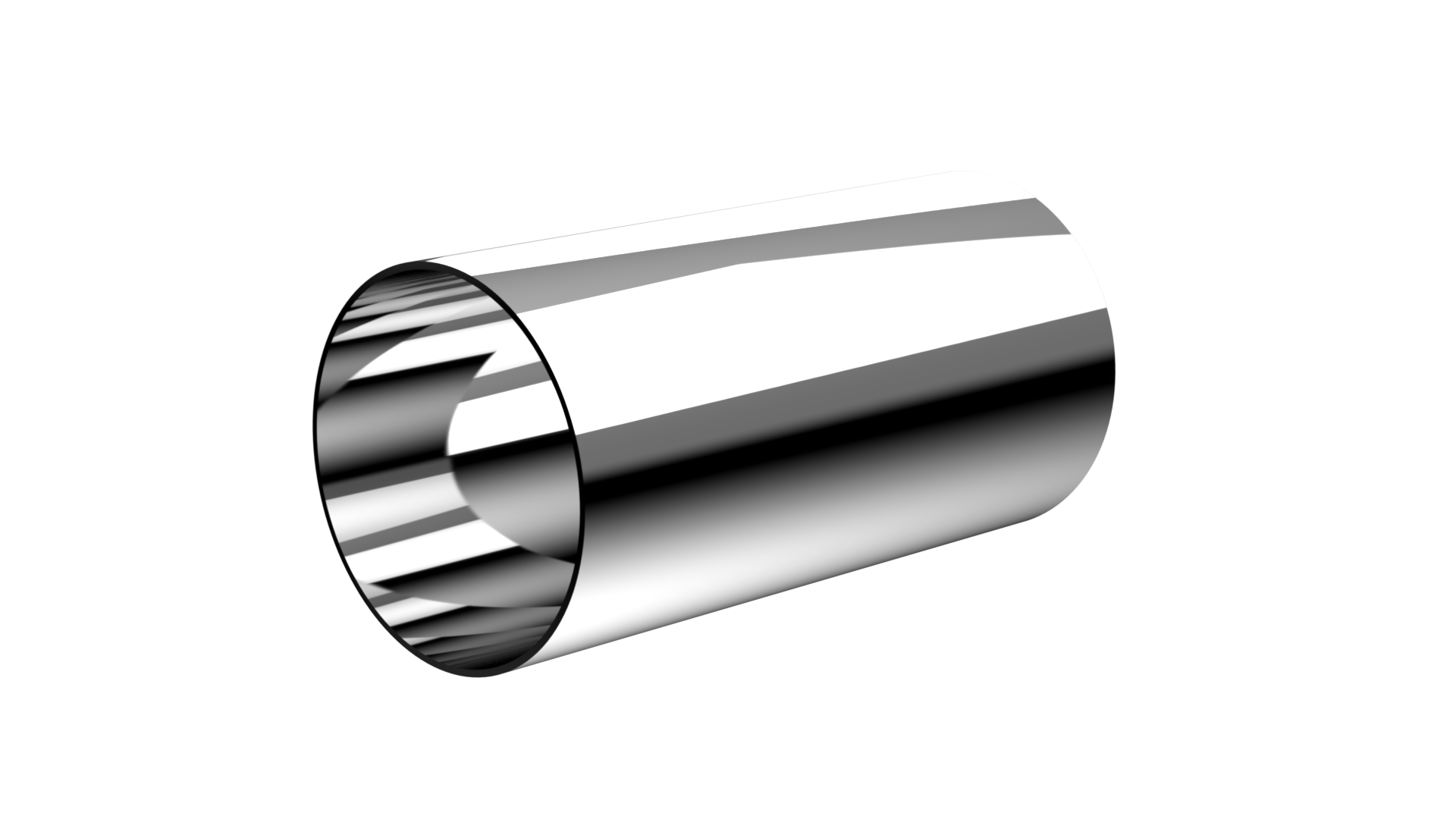
- Cylindrical section
The main structure of the tank, capable of withstanding the internal pressure and the flight's load.
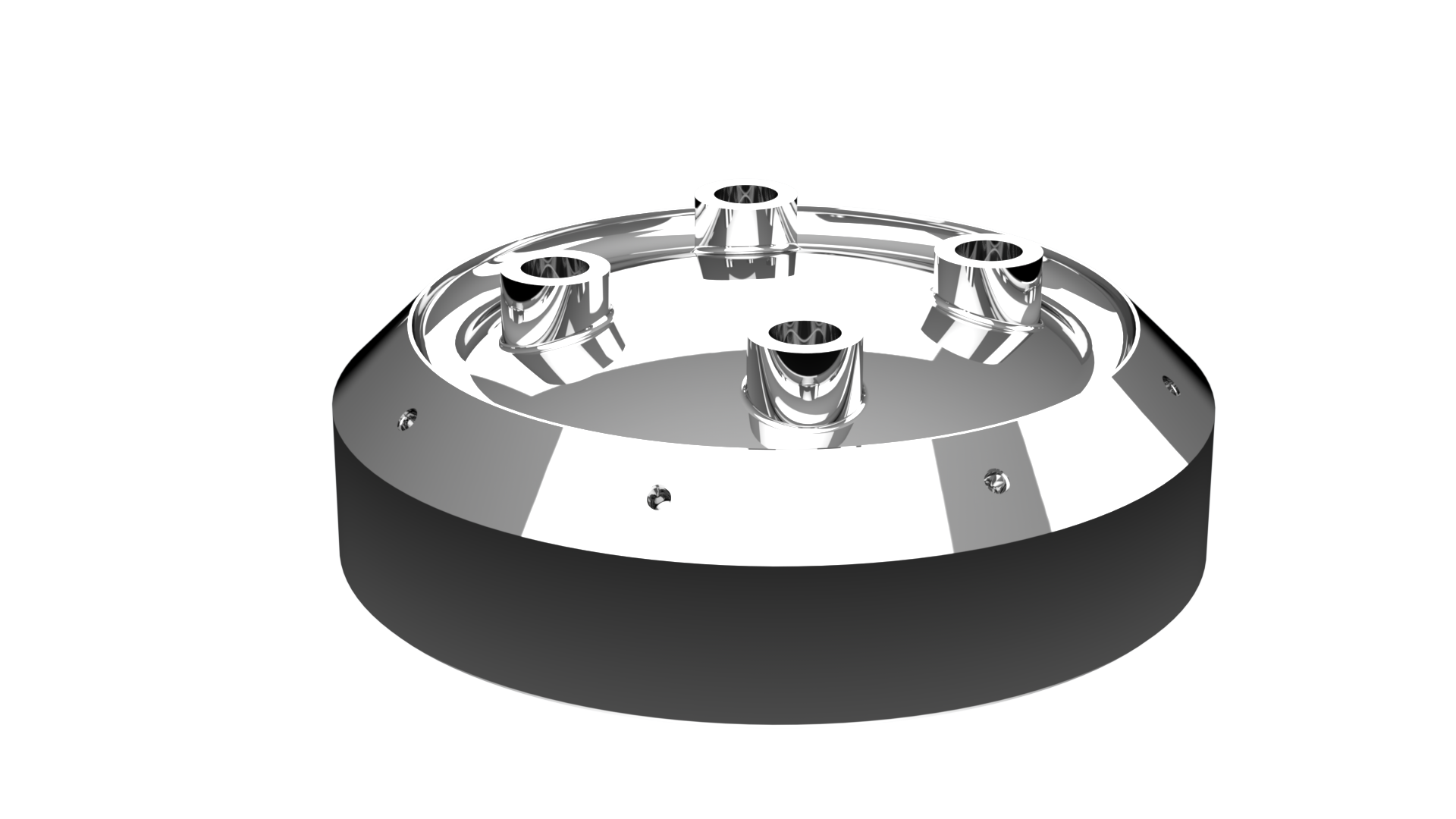
- End-caps
The part responsible for the inputs and outputs of the tank, in order to fill and use the propellant stored, and also host the different sensors.
¶ Finite Element Analysis
¶ Software
This FEA analysis was performed with the ANSYS Mechanical software for the static structural analysis and for the buckling simulations. The CAD of the different parts was designed using Solidworks.
¶ Type of simulation
Two main simulations were performed to analyse this assembly:
- A static structural analysis to estimate if the Von Mises constraints respect the requirements for the two load cases: 90[bar] and 120[bar].
- A linear buckling analysis to be sure that the structure will be able to support the pressure and the compressive forces.
¶ Goal of the simulation
The main goal of the FEA analysis is to ensure that the tank will withstand all the forces applied to it without dramatically exploding or imploding.
¶ Inputs
We use the following unit system: mm-t-N-s-mV-mA.
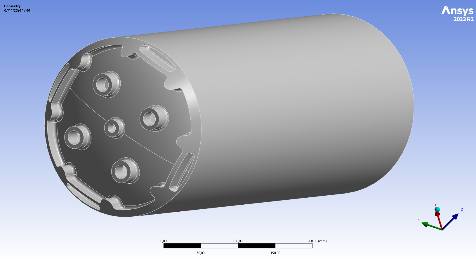
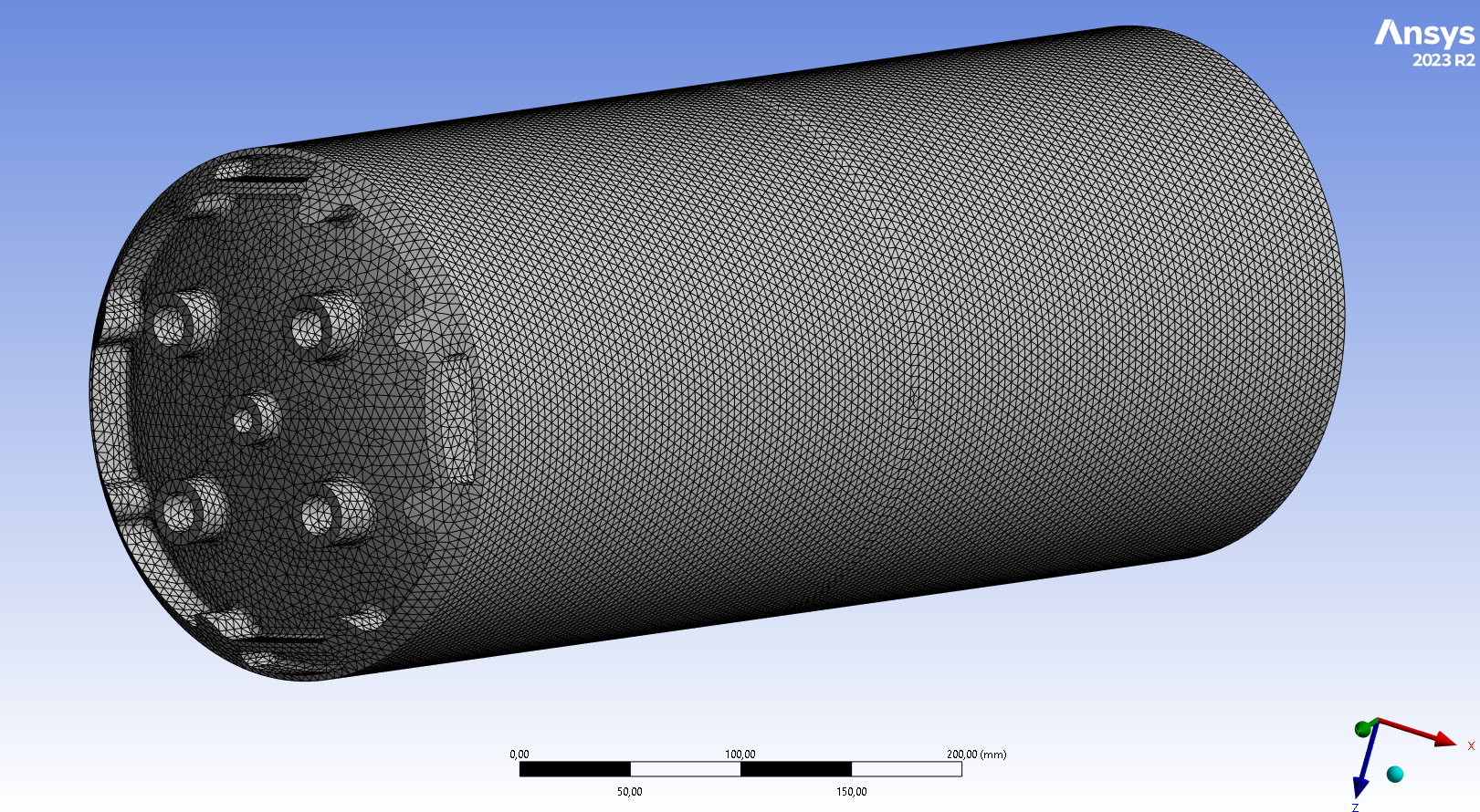
The geometry was pre-processed, we merged all the parts together and filled the screw holes on the couplers.
Bellow is an image of the final geometry:
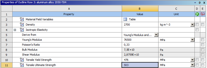
As we regrouped all parts into one, we choose to apply the less performant of the two materials to the whole geometry, aluminum alloy 2050-T8.
We used only the isotropic material properties, where we know the Young's modulus, the poisson ratio, the density, the Yield strength and the tensile strength. The following image shows the material properties implemented in the software.
Aluminum alloy 2050-T84 properties:
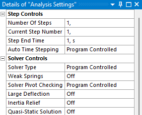
Time was not taken into account for these simulations.
- Static structural
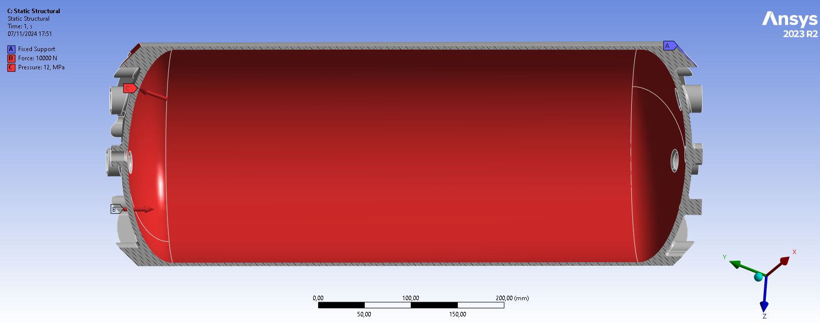
- Internal Pressure of 12 [Mpa] for the first load case and 9 [MPa] for the second: surface load, inside wall of the tanks.
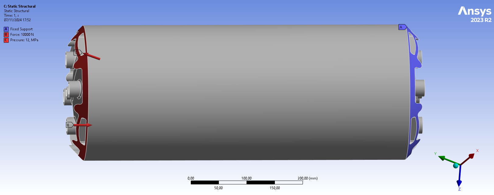
- Compressive Forces of 10 [kN] for both load cases: applied on the upper coupler to simulate the compressive forces of the rocket engine combined with the accelerated mass above the tank.
- Clamped surface: Lower coupler is blocked in all directions and rotations.
We can compare our simulation with the real world:
|--- | --- |
| Real case | Model |
| Small moment caused by the fins force | Not modeled |
| Weight of the propelant acting on the lower caps | Not modeled because significantly lower than the internal pressure of 90 or 120 [bar] |
| Compressive forces acting on both the upper and lower coupler | Clamped lower coupler and all the compressive forces applied to the upper coupler |
- Linear Buckling
- Internal Pressure of 12 [Mpa] or 9 [MPa]: surface load, inside wall of the tanks.
- Compressive Forces of 10 [kN]: applied on the upper coupler to simulate the compressive forces of the rocket engine combined with the accelerated mass above the tank.
- Clamped surface: Lower coupler is blocked in all directions and rotations.
Bellow are images of the boundary conditions defined in ansys. The first image shows the force applied on the upper coupler and the clamped coupler and the second image shows the pressure applied inside the tank:
Here is an image of the settings of the simulation:
¶ Mesh
We choose to use the 3D solid elements to realize our analysis. The mesh is constituted of tetrahedral mesh of quadratic element order (Tet10).
No refinement has been applied.
To refine the mesh, the maximum equivalent stress is chosen as the convergence criterion.
The 'size' quantity refers to the sizing setting applied on the geometry.
| Size (mm) | 10 | 5 | 3 |
|---|---|---|---|
| Load case 1 max eq. stress [MPa] | |||
| Deltas [%] | / |
We use the mesh with an element sizing of 5 [mm] as it is sufficiently refined (less than 2 [%] difference with the finest mesh).
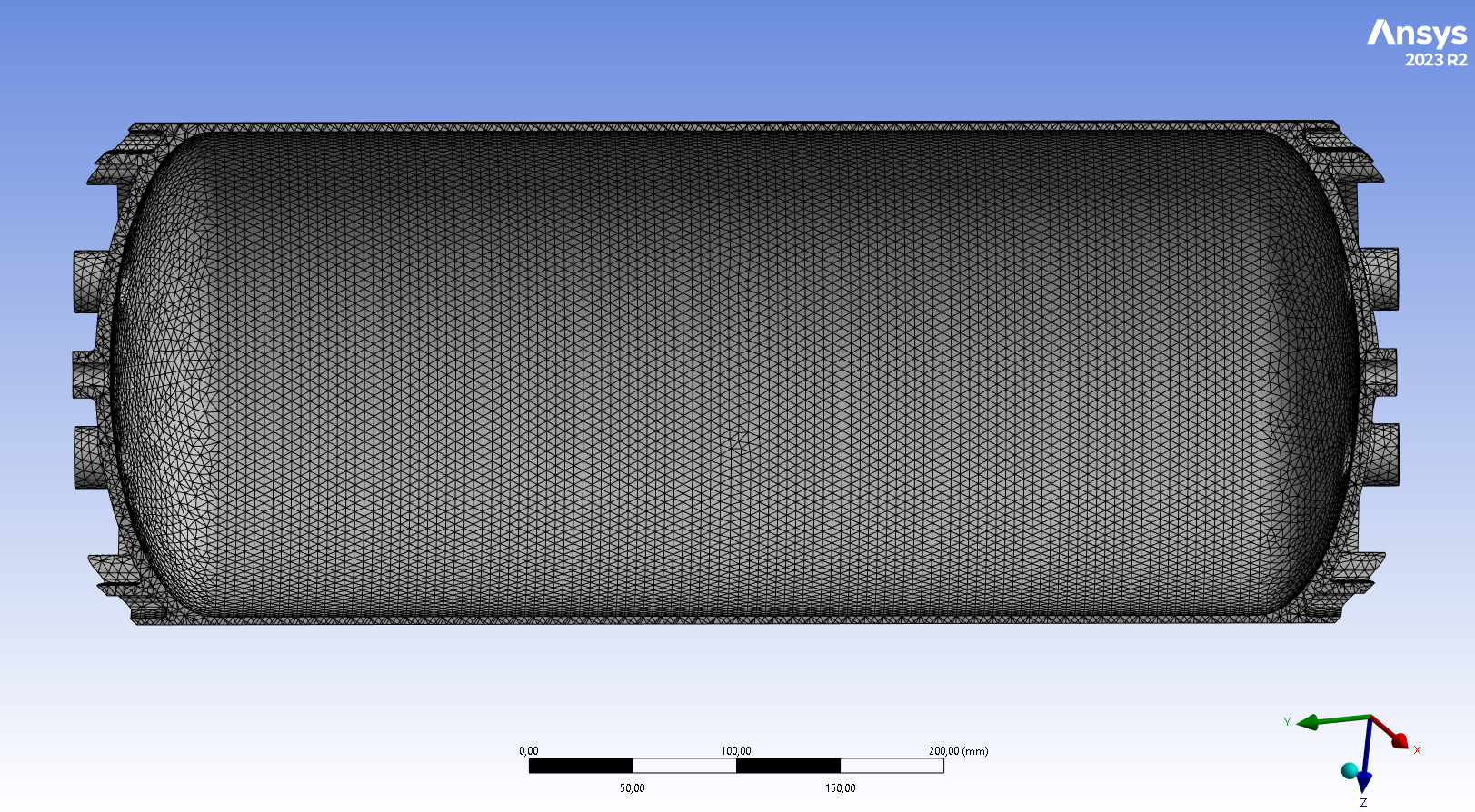
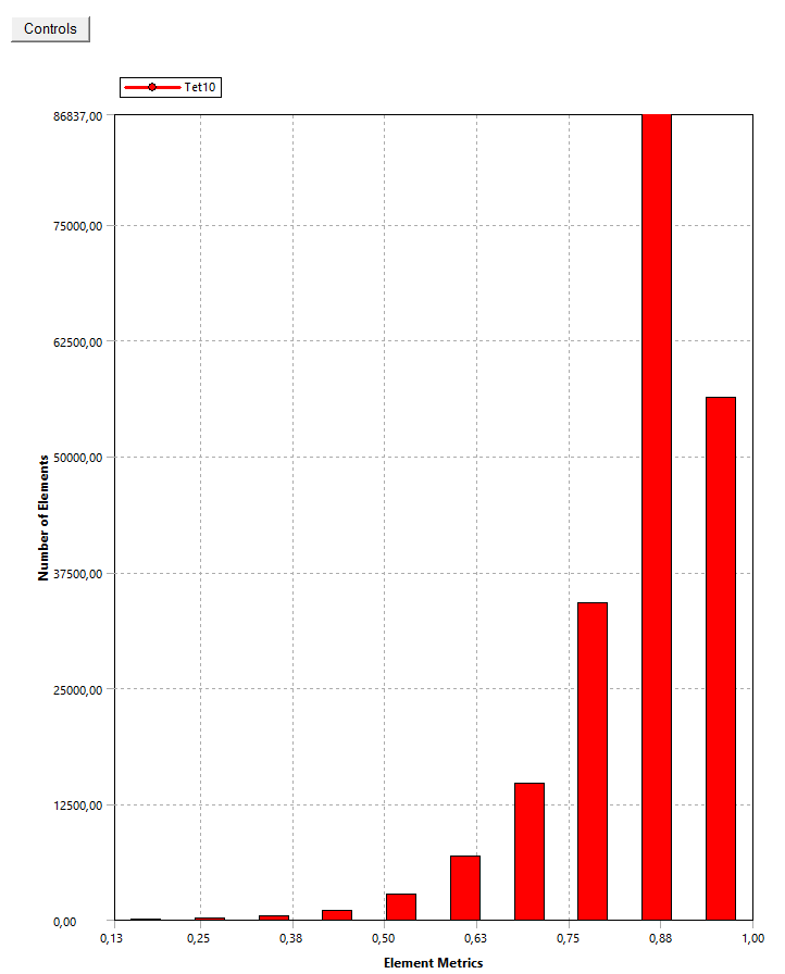
The final mesh is the one generated with an element sizing of 5 [mm] on the whole geometry. It contains 202880 elements. The average element quality is around 85%.
The following pictures illustrate the mesh inside and outside the tank as well as the element quality of the mesh.
¶ Outputs
The results that interest us are the equivalent stress and the buckling modes.
¶ First load case
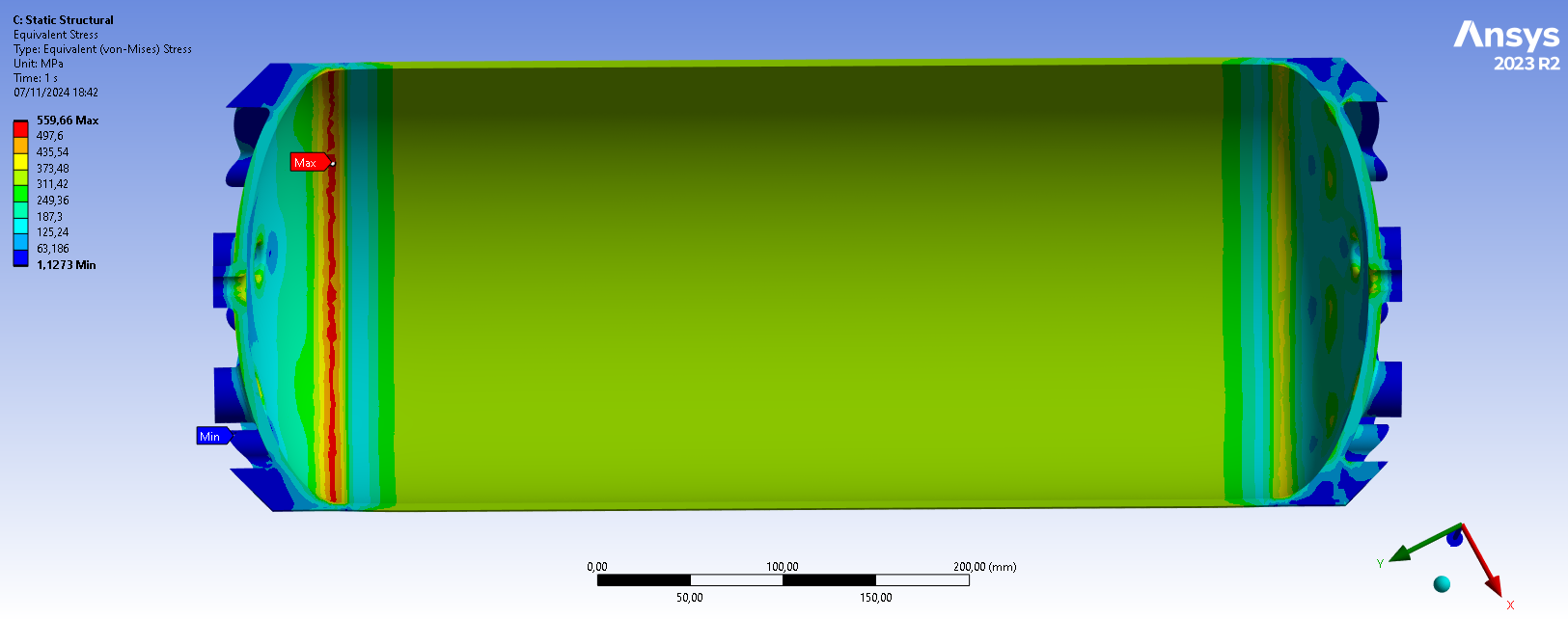
The maximal stress is found inside the tank on the upper coupler near the weld with the main body, its value is 559.66 [MPa]. The caps being manufactured in 2050-T84 aluminum alloy with a thickness of about 4 [mm], its tensile strength here is 503 [MPa], this limit is exceeded.
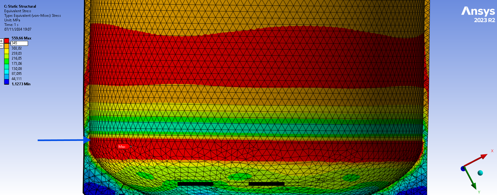
The image above shows the equivalent stress field near the weld between the upper cap and the main body which is indicated by the blue arrow. The scale has been modified in order to show the areas where the tensile strength of the weld is exceeded (i.e the areas in red). Thanks to that, we can see that this limit is exceded on the weld line. It is also exceeded on the weld line that closes the main body cylinder as we can see red areas that go around the circumference of the cylinder.
¶ Second load case
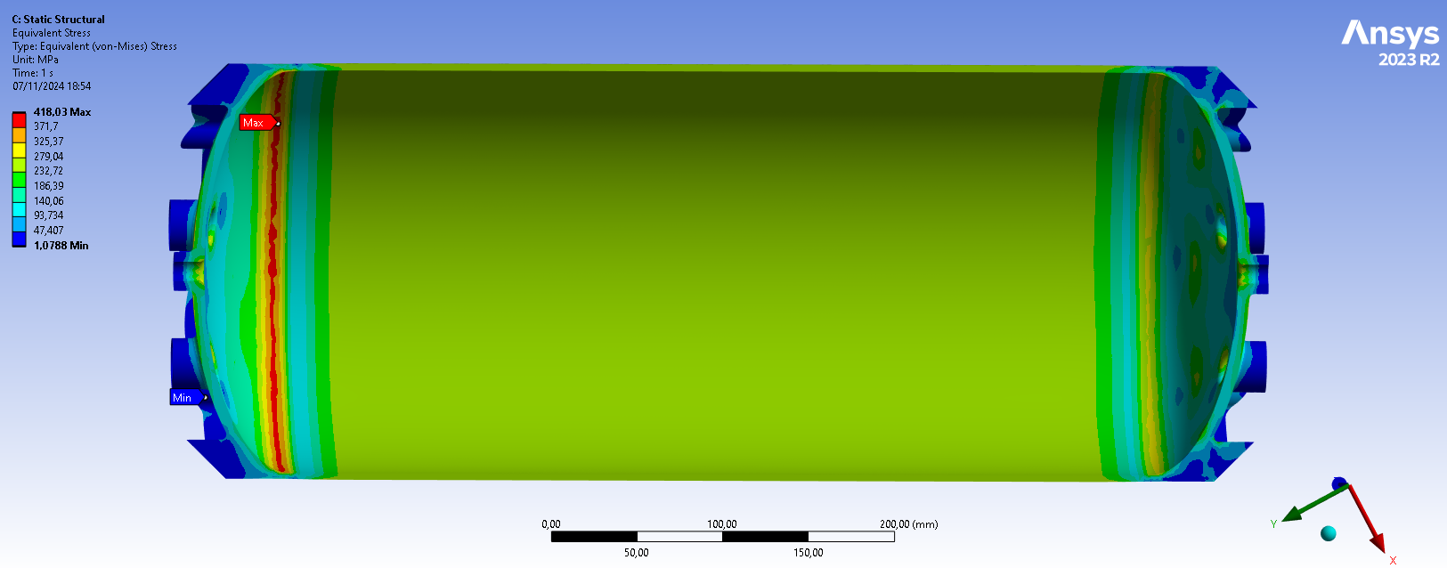
The maximal stress is found inside the tank on the upper coupler near the weld with the main body, its value is 418.03 [MPa]. The caps being manufactured in 2050-T84 aluminum alloy with a thickness of about 4 [mm], its Yield strength here is 476 [MPa]. Therefore the metal stays in the elastic domain in this load case.
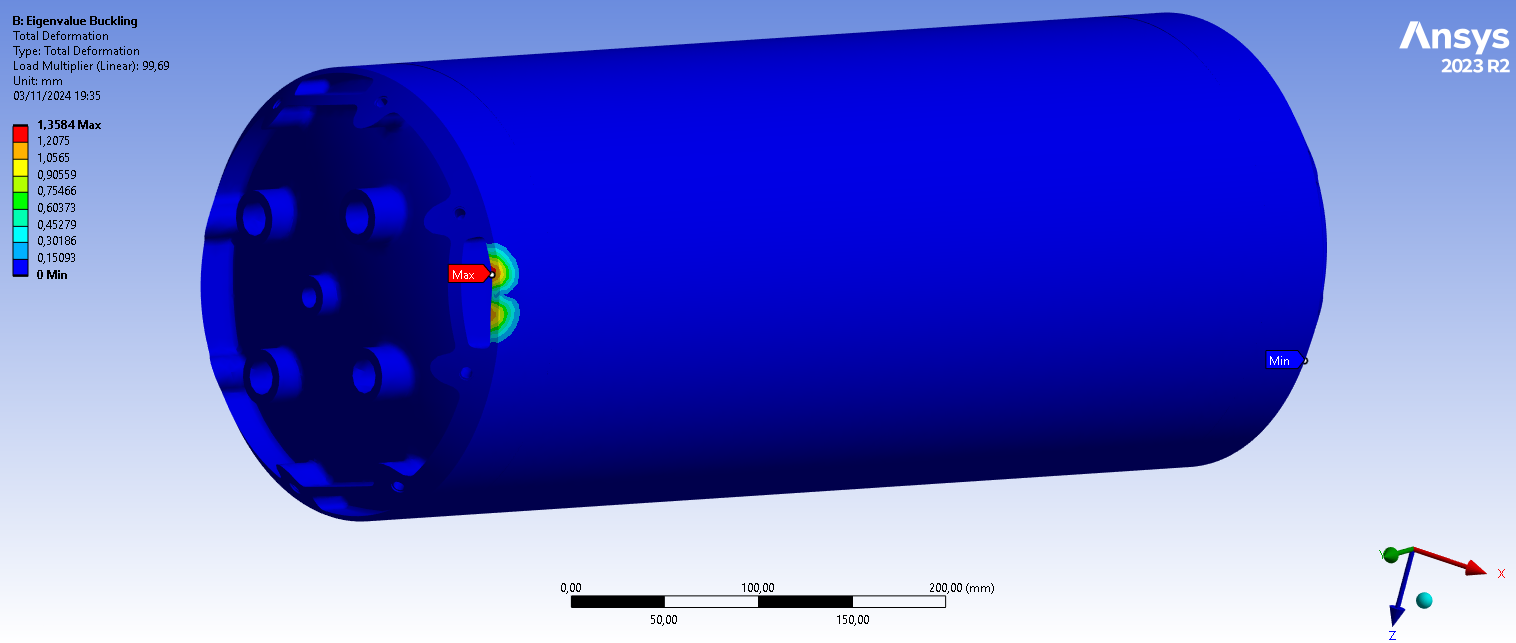
Below are the first 5 load multipliers of each load case given by the eigenvalue buckling simulation and an image of the 1st mode which is the most probable to happen. It is the same for the two load cases.
|---|---|
|Mode|load factors of case 1|load factors of case 2|
|1|||
|2|||
|3|||
|4|||
|5|||
¶ Equivalent stress
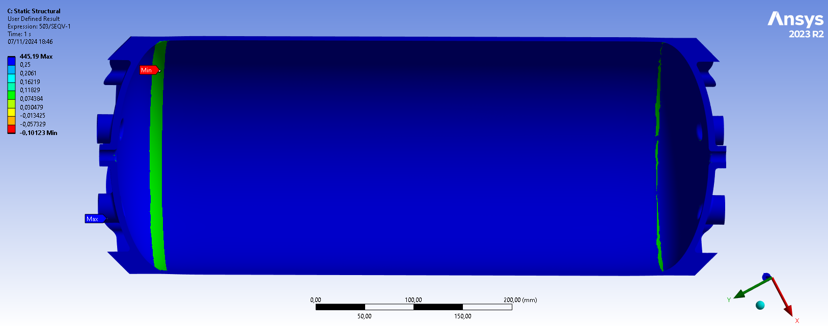
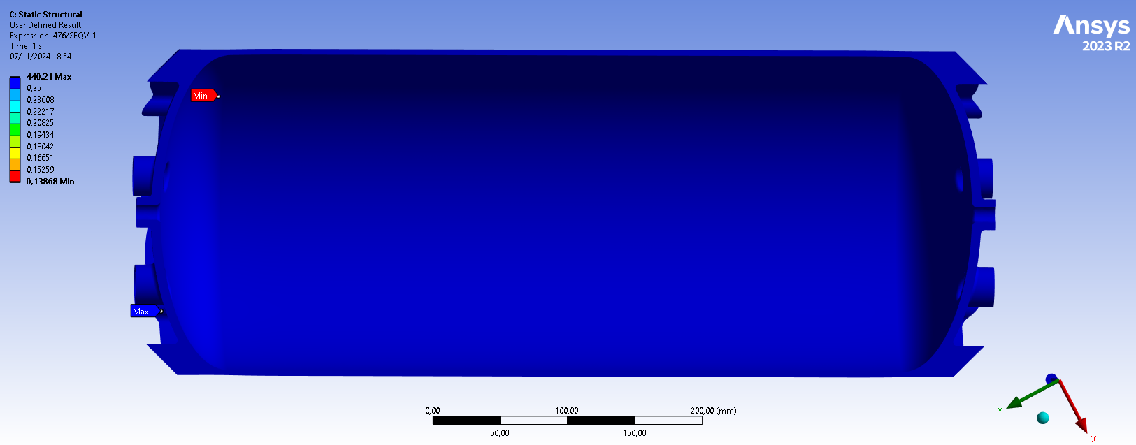
Below are images of the MoS field in the caps relative to their tensile strength for the first case and their yield strength for the second case. The scale has been modified in order to locate the areas where the MoS requirement (MoS>0.25) is not respected (i.e all areas that are not in blue). The minimal value of the MoS in the first case is -0.101 and 0.139 in the second case.
-
2024_C_SE_ST_REQ_37 Margins of safety for simulation validation
Unless specified otherwise, all parts shall be designed to withstand their design load with an additionnal Margin of Safety (relative to the elastic limit or other applicable failure criterion) depending on the part's nature: MoS 0.25 for all static simulations, MoS 3 for all buckling load cases, MoS 3 for all parts designed via generative algorithms. -
1st load case:
-
2nd load case:
Even though the MoS shown here has bean calculated with the caps' tensile strength we can still conclude that the MoS in the main body is higher than 0.25 as its tensile strength and yield strength are greater than the caps'.
We have also computed the MoS field in the geometry relative to the tensile strength of the weld in the first load case:
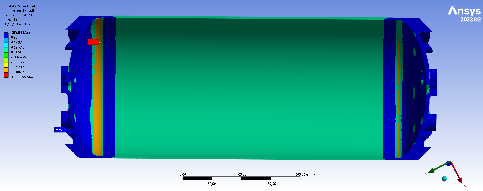
We can see that the requirement is not respected on the welds.
¶ Buckling
For linear buckling, we have the following equation:
Where is the th load multiplier, is the load applied and is the th buckling load extracted by the linear eigenvalue buckling analysis.
Moreover, our formula for the margin of safety is:
Plugging in the lowest load factor gives us the lowest MoS:
This means that the requirement for buckling load cases is respected as .
¶ Interpretation
¶ Simulation validity
We will discuss the validity of the simulation by calculating by hand the pressure found in the cylindrical main body of the tank and comparing it to the results of the simulation.
We have the following equation for the maximal principal stress in a cylindrical pressure vessel:
With being the gauge pressure in the tank, the radius of the cylinder and the thickness of the cylinder.
Plugging in these values in the equation gives us the following result:
By comparison the simulation gives a result of approximately 382.5 [MPa] as we can see on the following image:
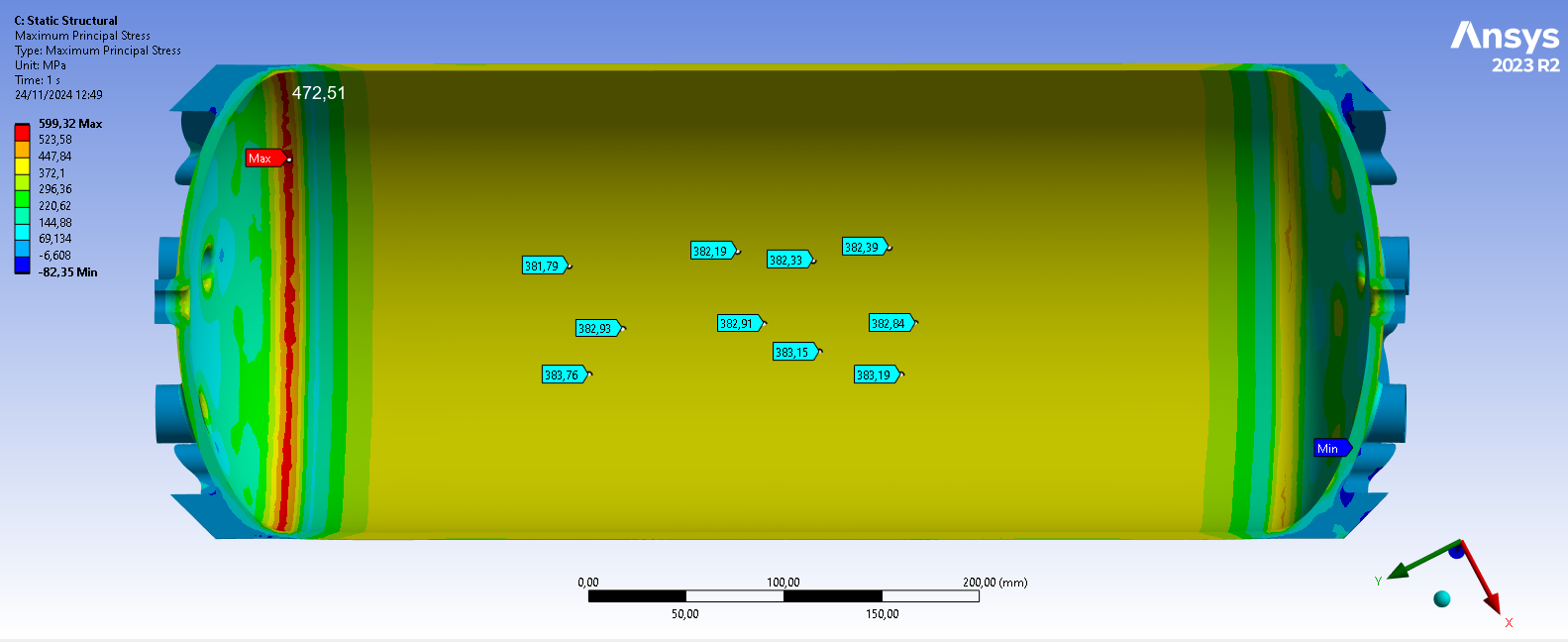
Therefore we can validate the simulation as the simulation results are similar to the theoretical value.
¶ Conculsions
The two main focuses of this simulation were:
- Determine if the tensile strength and the yield strength of the aluminum alloys are exceeded when the tank is pressurized to 120 [bar] and 90 [bar] respectively:
The simulation results indicate that with a 120 [bar] pressurization, the welded aluminum 2195 T8's tensile strength is exceeded where there will be welds. This signifies that such a pressurization might cause catastrophic failure.
Under a 90 [bar] pressurization, the yield strength is not exceeded, however the MoS requirement is not respected, as the lowest MoS in this case is 0.135 which is lower than the 0.25 required.
As our value for the weld's tensile strength is not very precise and the simulation results do not exactly match the theoretical results, we will proceed to real tests when the first tanks are manufactured.
- Determine if the tank is prone to buckling under the compressive forces:
The results of the eigenvalue buckling simulation are more positive as they indicate that no buckling will occur under the specified load cases.