¶ Introduction
This document presents the general design chosen for the cryogenic tanks of the rocket.
The tanks store the fuel and the oxidizer of the rocket.
It is the first year using LOx as oxidizer → cryogenic temperature (-183 °C).
The tanks are connected to each other by the mid bay and are connected to the rocket structure by the couplers.
¶ Definitions and Abbreviations
- LOx : Liquid Oxygen
- ETH : Ethanol
- FoS : Factor of Safety
¶ Relevant Knowledge Needed
The tanks shall withstand the flight and pressure loads on their own: Flight loads are way lower than the pressure loads → focus on the pressure.
The tanks have to keep 17 L of LOx for 8 min → anticipate evaporation and need an empty volume for better pressurization
- 2024_C_SE_ST_TANK_REQ_03 Tank volume
The tank shall contain [24][+2/-0]L of volume. - 2024_C_SE_ST_TANK_REQ_04 Tank length
The tank bay shall have a length of [840][+/-20]mm. - 2024_C_SE_ST_TANK_REQ_07 Tank module mass
The total mass of the tank module shall be [8500][+/-600]g. - 2024_C_SE_ST_TANK_REQ_08 LOx isolation time
The tank shall be able to keep at least [17]L of liquid oxygen that was injected at a temperature of [-183]°C and a pressure of [15]bar in a liquid state for [8]min. - 2024_C_SE_ST_TANK_REQ_12 Tanks interchangeability
The tank containing the liquid oxygen shall be mechanically identical to the tank containing the liquid ethanol so that both tanks may be interchangeable.
The tanks must withstand the following loads:
- Nominal pressure of 60 [bar] with FoS of 2 (capable to hold 120 [bar])
- Tested at 1.5 times nominal pressure: 90 [bar]
¶ Design Options
There are two designs, one in aluminium and one in stainless steel. The reason is that the competition might ban the use of stainless steel, due to an incident during the last edition. Indeed, at low temperatures, stainless steel is very brittle and might cause a dangerous explosion if a surpression occurs.
¶ Material properties:
- Yield strength: 800 [MPa]
- Density: 7'900 [kg/m3]
¶ Multiple parts:
- Tube as main body with 2[mm] thickness and 200[mm] internal diameter
- Two 2.2[mm] thick identical caps
- Four G1/2 inserts on each cap
- Two couplers: one male, one female
Final mass: approximately 10.3 [kg].
Final volume: 24.086 [L].
Main Advantages: easy to work with steel, very cheap
Main Disadvantages: many parts to assemble, slightly too heavy, implies a steel/aluminium interface or steel coupler
Manufacturing procedure :
• Preparation of a 3 mm (or more if needed) metal sheet: cut to the right size and chamfer on opposite sides for welding
• Rolling of the sheet to the desired diameter
• Welding along the length of the resulting tube
• Preparation for the caps welding: chamfers on both ends of the tube
• Caps:
- Purchase of the caps because they exist on the market (Notz Metall)
- Drilling of four holes for the inlets and outlets
- Welding of the connections
- Preparation for caps welding by making a chamfer
• Welding of the caps on the main body
• Possibility of post-welding machining of the seam between the caps and the main body
• Machining of the tank to achieve the desired thickness: 2.2 mm for the caps and down to 2 mm for the walls
• Welding of a pre-machined version of the coupler
• Test pressurization of the tank in order to highlight eventual deformations
• Final machining of the coupler
The estimated cost of one tank is 300 CHF.
Material properties:
- Yield strength: 250 [MPa]
- Tensile strength: 290 [MPa]
- Density: 2'700 [kg/m3]
Parts:
- Tube as main body with 5[mm] thickness and 200[mm] internal diameter
- Two identical machined caps with integrated coupler interface
Final mass: approximately 9.23 [kg].
Final volume: 24.086 [L].
Main Advantages: small number of parts, lightweight
Main Disadvantages: expensive (due to EBW), welding difficulties,
The use of an other alloy might be interesting: AL-2195 T3/T8. This material would significantly reduce the mass of the tank.
Using conventional welding, it is challenging to obtain a watertight weld. For this reason, we will explore electron beam welding (EBW) or friction stir welding (FSW) to counter the problem. The goal is also to avoid the need for annealing the part.
Manufacturing procedure :
• Cutting a sheet of 670 X 629 mm and of 2.5-5 mm thickness (to be determined)
• Rolling a tube from the sheet to a 200 mm internal diameter (main body)
• Welding along the 840 mm side with FSW/EBW
• CNC machining of the caps (with the coupler, inlets and outlets integrated) from a solid aluminium alloy bloc
• Welding of the caps on the main body with FSW/EBW
• Possible thermal treatment
If FSW is used, there will be no need for a post welding machining as with this method, the melting point of aluminium is not attained.
¶ Simulations
¶ Thermal Simulation
The insulation is simply a 7[cm] (might be modified) thick polystyrene shell that surrounds the tank. It will be removed right before the launch of the rocket, with a separation mechanism. This insulation has a density of 10[kg/m3] and a thermal conductivity of 0.035[W/mK]. The following simulation is performed using LOx at 90[K] and an external temperature of 303[K] with a convection coefficient of 10 [W/m²K] at this temperature. The result is the temperature distribution in the tank after 10 minutes. After those 10 minutes, the tank will have 17 [L] of LOx left, so 30% of the total volume will be evaporated.
We will adapt the next simulations by using the selected aluminium alloy tank, and an external temperature of 313[K] as it is a closer temperature to the real conditions in Portugal .
The simulation satisfies the requirements considering that the boiling temperature of LOx increases as pressure increases (see phase diagram).
For the insulation, we chose to stick with the polystrene shell, as it is a very cheap and efficient material that can be easily purchased and manufactured. Currently, the design consists of two half cylinders connected with rods to two servo motors attached to the rail of the launch pad. Right before takeoff the two motors will be activated and will separate the insulation, leaving room for the rocket to pass.
We are still looking for other design options to ensure that the two insulation pieces will be separated, as putting springs inside the cylinders so they will be separated anyway in case of electronic failure. The inconvenience with this spring mechanism is the incapacity of rapidly closing the insulation in case of necessity, causing a high loss of liquid oxygen as the tank heats up.
¶ Mechanical simulations
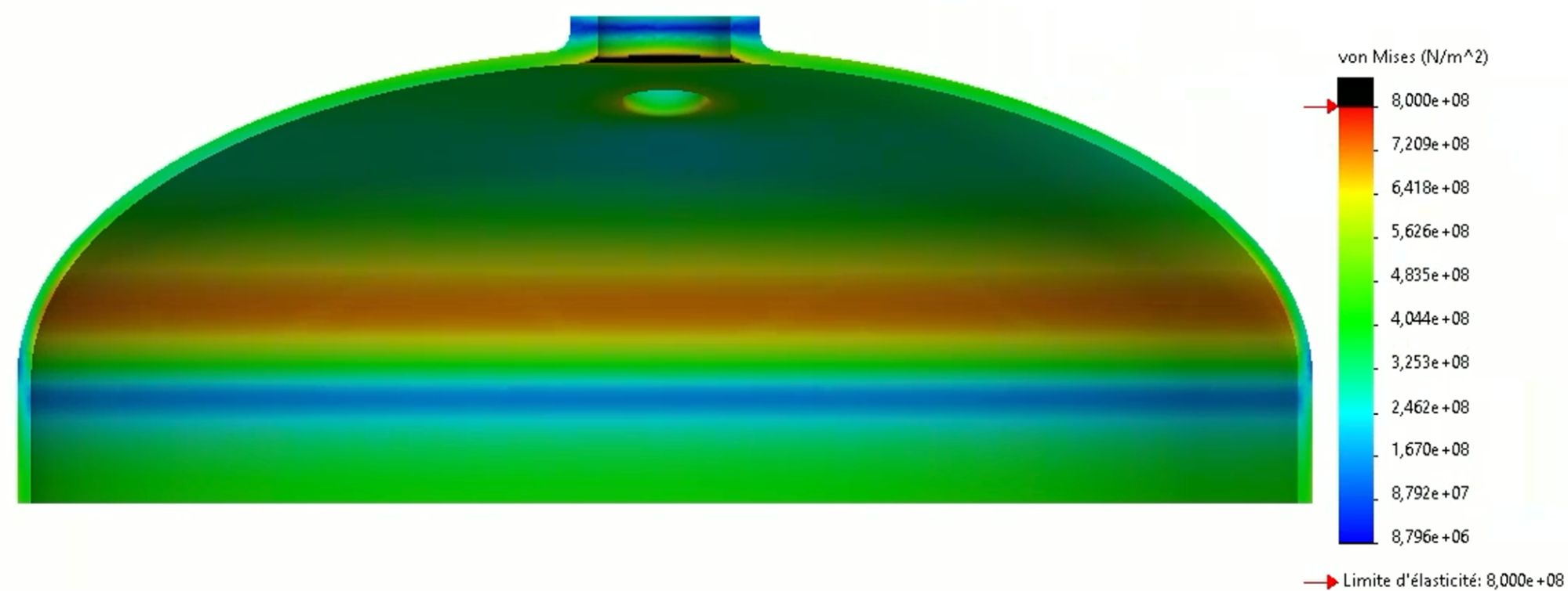
For steel, we only perform simulations at 120[bar] because we have to be below the yield strength when testing with twice the nominal pressure (that is not the case for aluminium).
A first rough simulation shows that everything is good in the main body but there are some areas where the yield strength is exceeded. Some of them are created by the way we decided to clamp the tank (so we can ignore them), and the remaining are located in the caps. Then we need to conduct a more precise simulation on the cap by choosing a smaller mesh size.
The more precise simulation is depicted below and we see that the only critical areas are around the holes for the fittings (holes location are not accurate on these images but the simulation is still valid). These zones do not present any risk because the simulation do not consider the fittings that would reinforce the cap when welded.
For aluminium, when simulating wit a FoS 2, we should not exceed the tensile strength (290 [MPa]). Moreover, with a FoS of 1.5, we have to stay under the yield strength (250 MPa).
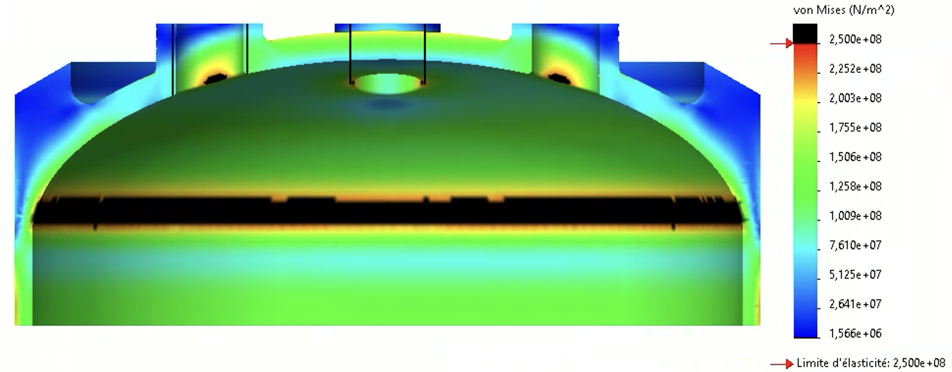
Depicted below is a simulation on the cap at 120[bar]. We see some areas in black where the yield strength is exceeded.
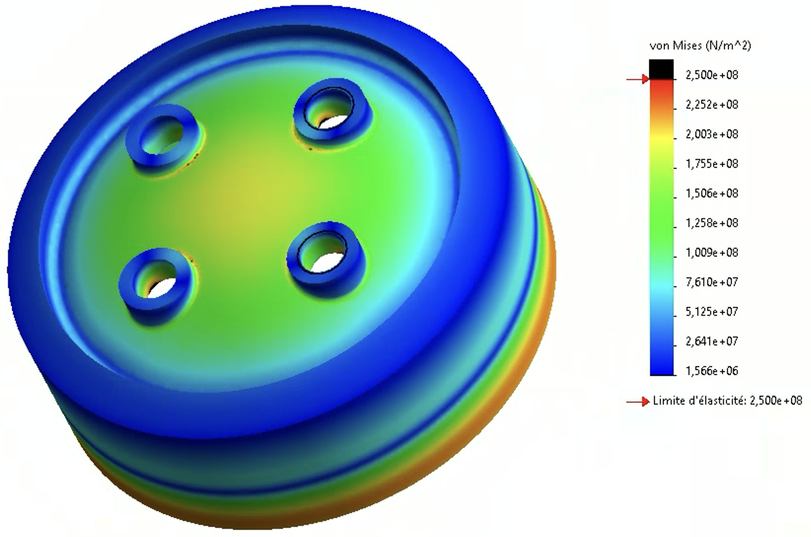
The following view better shows all the critical regions (in black). However, the maximum stress in the cap is 286[MPa], so it is lower than the tensile strength.
Now that the simulation is valid at 120[bar], we must check that it is also valid at 90[bar]. The corresponding simulation is presented below.
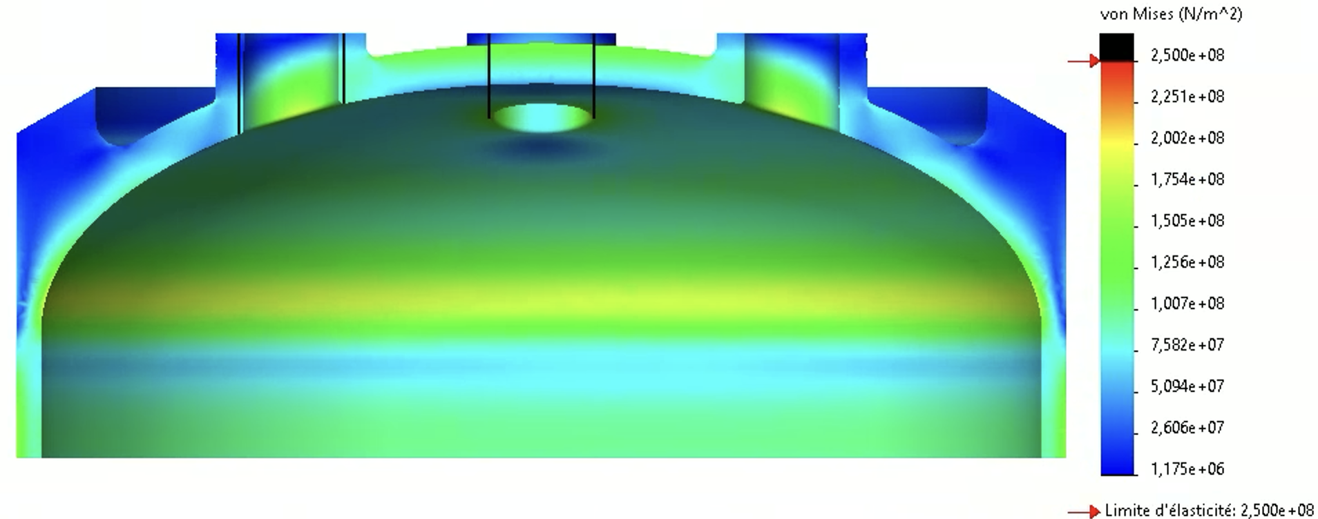
We clearly see here that the yield strength is not exceeded as the maximum stress is 212[MPa], so the requirements are satisfied and this design is valid.
¶ Narrowing design
The aluminium design is preferred because it allows to avoid a steel coupler that would significantly increase mass. Furthermore, there are less constraints with aluminium regarding the rules at EuRoC that might change and ban the use of steel.