¶ Interface ST - AV
¶ Interface Description
This document will be used throughout the development of Firehorn to track and manage the interface concerning the Structure and Avionics sub-systems. It aims to clearly state and provide further information on all the different features and parts that make possible safe integration of the Avionic sub-system into Firehorn.
¶ Interface type
Physical
Energy
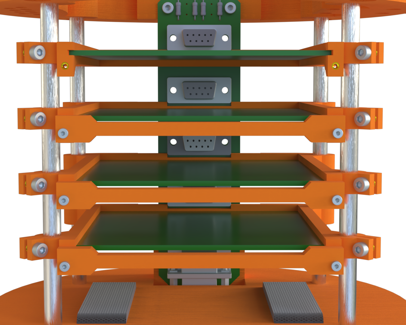
¶ Avionics Bay overview
The following diagramm shows where the different elements are located in the avionics bay.
The exploded view belows shows the avionics bay with the GFRP access panels and the antennas ground planes
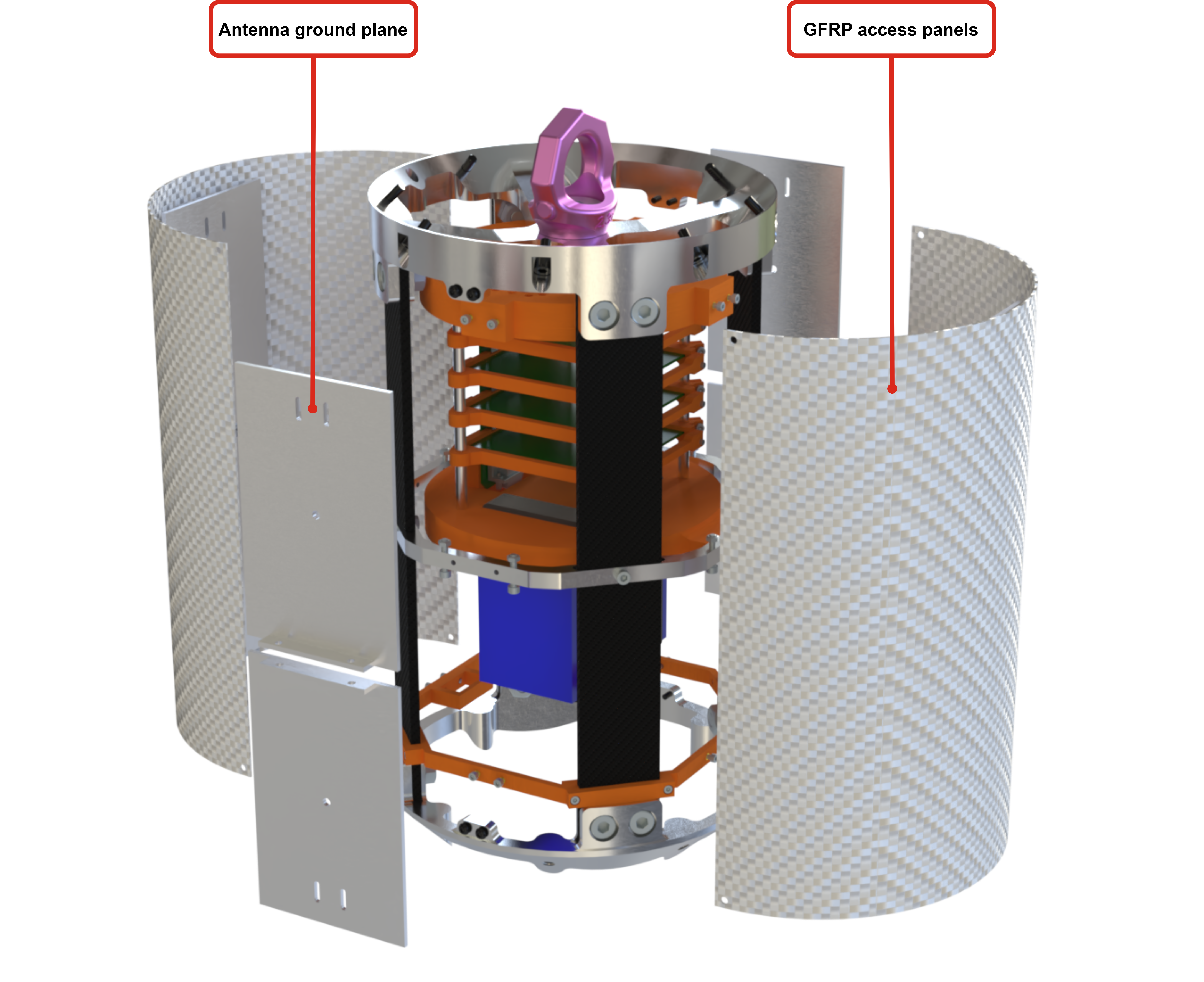
The avionics bay consist of the following main elements. It holds the AIS and the antennas.
The AIS is inserted from the bottom of the avionics bay.
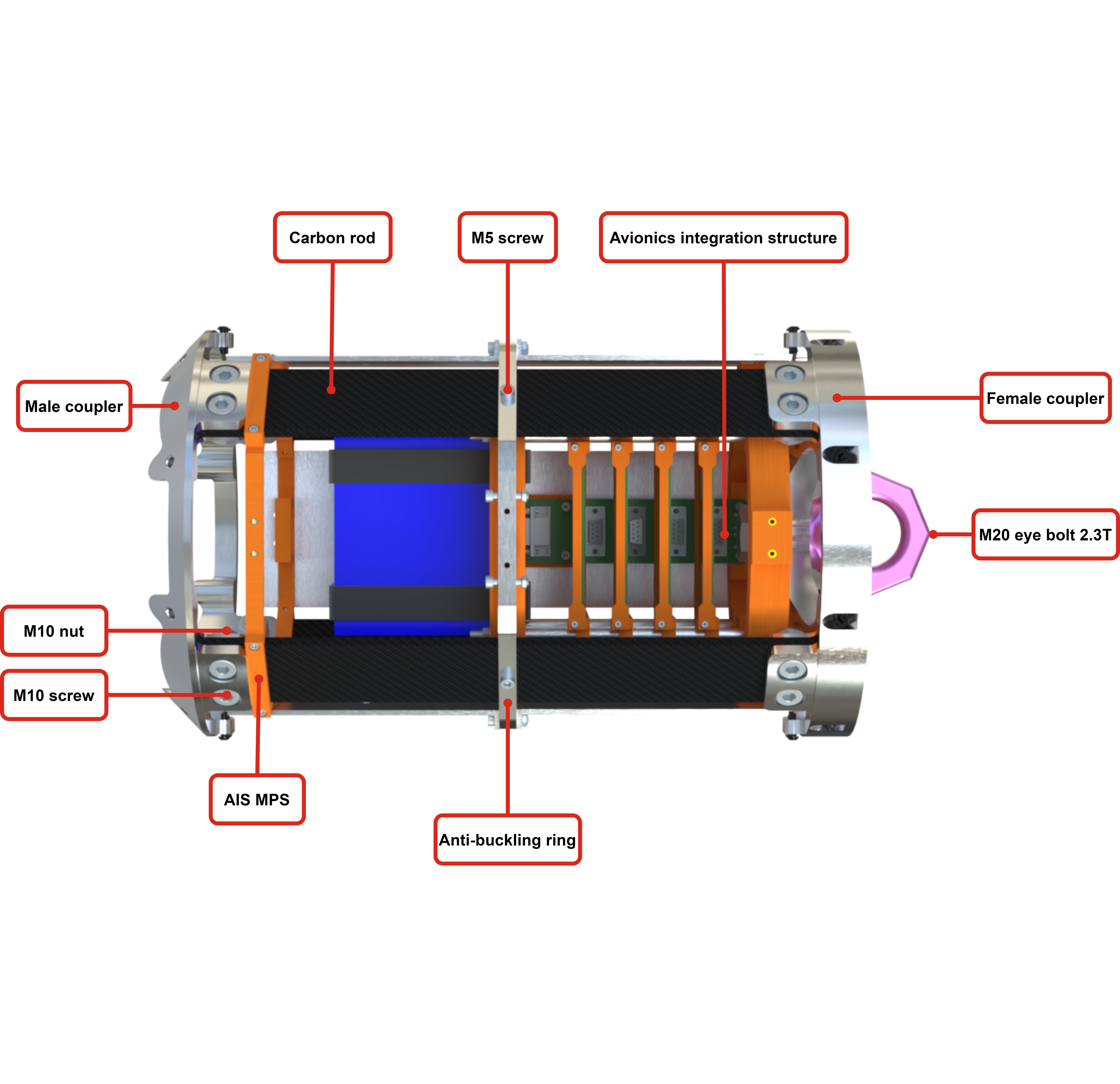
¶ Avionics Integration Structure - AIS
The AIS, located in the Avionics Bay, is used to host the AV PCBs and the battery.
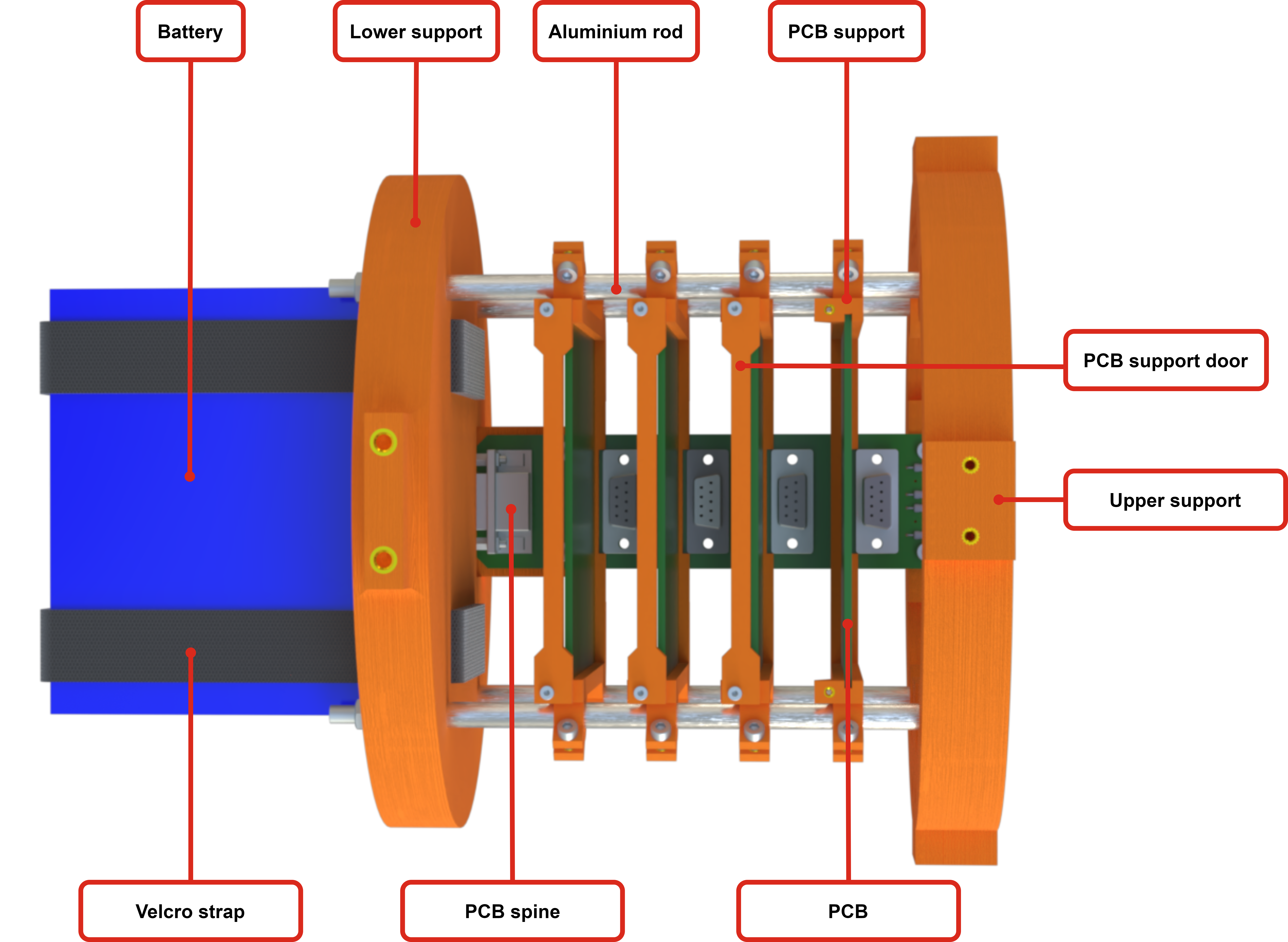
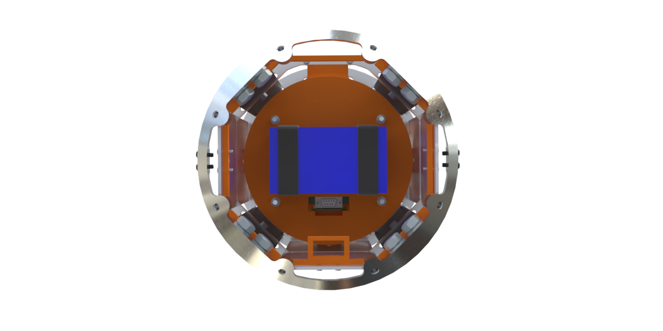
Close up view of the PCB stack
¶ Diagram 2 (Subsystem 2)
Separation mechanism to be added
¶ Diagram 4 (Subsystem 3)
Other AV PCB FasteningStructure to be added
¶ Enumerated Interfaces
¶ Interface Plane
Avionics integration structure (AIS)
- Fastnening holes on AIS (M3) - Spine: 2024_C_AV_SPINE_DDF
- Slide in brackets with locking mechanism - PCBs:
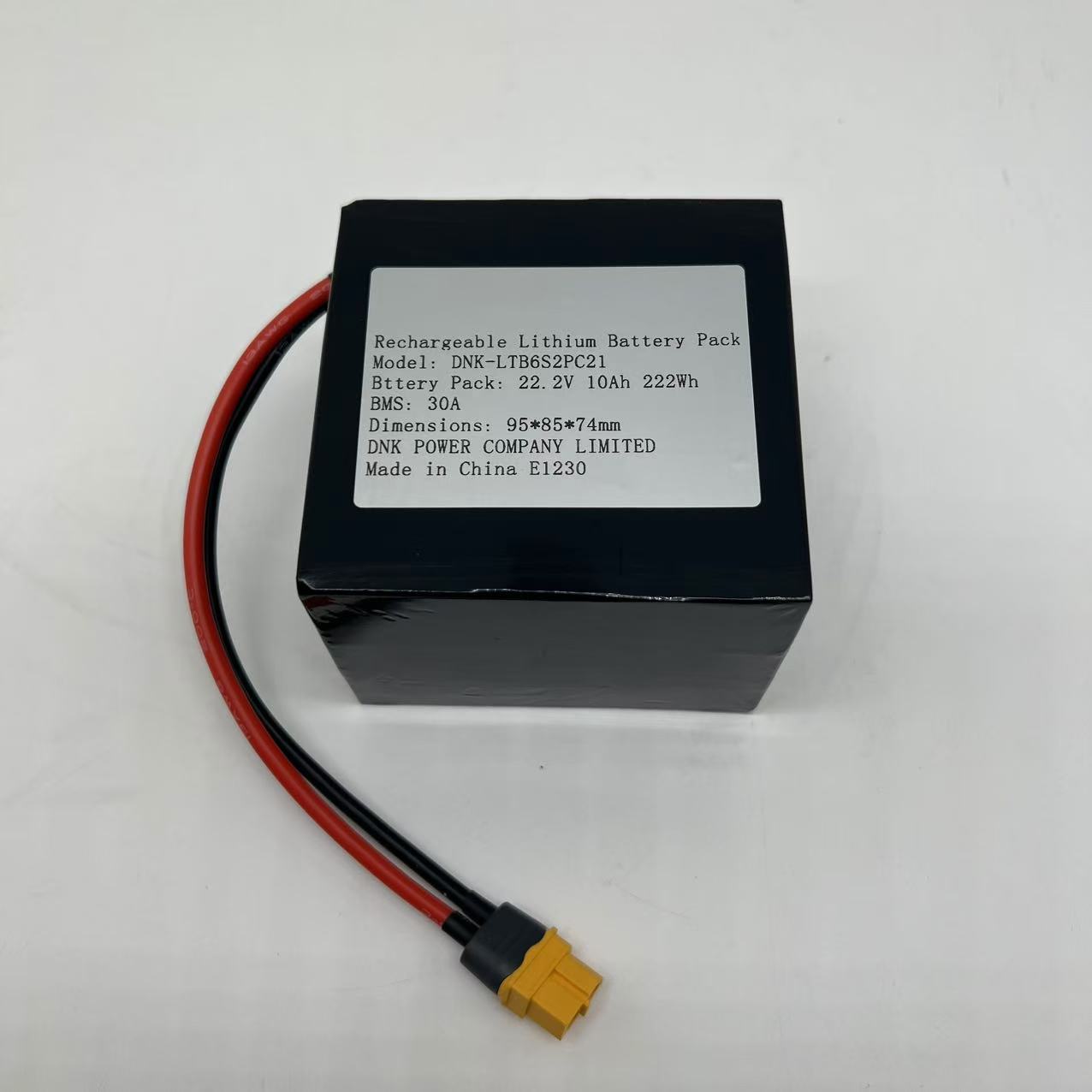
- AIS lower support and velcro - Battery: 95x85x74mm (lxwxh)
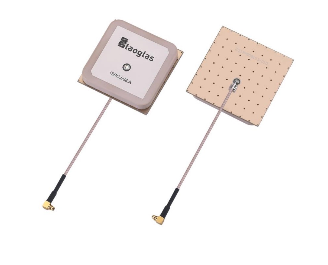
Antennas
The 8 antennas are mounted onto the 8 antenna ground planes which are themself fastened to the AIS MPS, the ABR and the AIS upper support
TBA: RF splitters
Cable management
Possible solution for cable management along the rods
Does AV has a list of number of cables (and there diameter) where they need to go to and from where ?
- Aerocover - Cable:
- Airframe - Arming Devices: [Q3 SEG_8] x2
Connectors between modules
| Interface | Intranet cables | High power cables |
|---|---|---|
| AV - Recovery Pyrocutter | N/A | FGG.0B.302.CLAD42 + PHG.0B.302.CLLD42 |
| AV - Separation Mechanism Pyrocutter | N/A | 2x DC cables |
| AV - Pressurant Bay | Custom T-connector | FFA.2S.302.CLAC52 + PCA.2S.302.CLLC52 |
| AV - Mid Bay | Custom T-connector | FFA.2S.302.CLAC52 + PCA.2S.302.CLLC52 |
| AV - Engine Bay | Custom T-connector | FFA.2S.302.CLAC52 + PCA.2S.302.CLLC52 |
¶ Interface Data
Separation Mechanism trigger
- Voltage: 5 [V]
- Amperage: 1 [A]
¶ Verification models for other subsystems
A prototype of the AIS will be 3D printed, it can be used by AV to test the interfaces.
¶ Relevant Requirements
- 2024_C_SE_ST_AVIONICS-BAY_REQ_01 AV bay declaration of purpose
The AV bay shall host the AV systems of the LV. - 2024_C_SE_ST_AVIONICS-BAY_REQ_02 AV bay antenna integration
The AV bay should provide non structural anchoring points for antenna panels. - 2024_C_SE_ST_AVIONICS-BAY_REQ_03 AV length
The AV bay shall have a maximum length of [350]mm. - 2024_C_SE_ST_AVIONICS-BAY_REQ_07 Length available for AV
The length available for AV contained inside the integration diameter shall be at least [300]mm. - 2024_C_SE_ST_AVIONICS-BAY_REQ_06 Structure type
The AV bay structure shall be internal so that its inside can be accessed radially.
- 2024_C_SE_AV_MECHANICAL_REQ_01 AV length
The avionic assembly located in the AV bay shall fit in a cylinder of [190]mm diameter and 300[mm] height. - 2024_C_SE_AV_MECHANICAL_REQ_03 Axial mass distribution
The Center of Mass of the AV Bay shall be no more that [10]mm from the LV's central axis. - 2024_C_SE_AV_MECHANICAL_REQ_04 Electronics accessibility
All switch, connectors and otherwise useful-to-tinker-with electronics should be accessible on the launch rail when the external panels opposite the launch rails are removed. - 2024_C_SE_AV_MECHANICAL_REQ_05 Cable management
All safety critical wiring shall implement a cable management solution (e.g., wire ties, wiring, harnesses, cable raceways) which will prevent tangling and excessive free movement of significant wiring/cable lengths due to expected launch loads. - 2024_C_SE_AV_MECHANICAL_REQ_06 Secure connections
All safety critical wiring/cable connections shall be sufficiently secure as to prevent de-mating due to expected launch loads. - 2024_C_SE_AV_MECHANICAL_REQ_07 Cryo-compatible wire insulation
Any wiring or harness passing within close proximity of a cryogenic device (e.g., valve, piping, etc.) or a cryogenic tank (e.g., a cable tunnel next to a LOX tank) shall utilize safety critical wiring with cryo-compatible insulation - 2024_C_SE_AV_MECHANICAL_REQ_09 Recovery systems energetic devices
All energetic device arming features shall be externally accessible/controllable. - 2024_C_SE_AV_MECHANICAL_REQ_10 Arming device location
All energetic device arming features shall be located on the airframe such that any inadvertent energy release by these devices will not impact personnel arming them.
¶ Interface Verification Tests
¶ Updates
-
Infrastructure physique → Avionics Integration Structure (AIS)

- Bloquer la taille et l’orientation du AIS d’ici la fin de semestre
- Orientation via taille de batteries, taille de batteries via power budget, power budget via measurements sur proto
-
Airframe RF transparent ?
- GFRP anyway
- Regarder avec le lab pour antennes
-
Rods conducteurs
- Envoyer des vues en coupes / photo / etc. pour AV pour qu’ils gèrent l’orientation des antennes
-
Cable management vers RE BAy
- A définir avec RE plutôt
-
Le fait qu'actuellement on a un TM ST qui s'occupe de développer la structure d'intégration de l'AV dans l'AV Bay, mais qu'il y a selon moi un travail similaire à faire dans les autres bays ou AV est présent. Je pense du coup que ça fait sens qu'un TM ST s'occupe aussi du design de MPS qui permettent d'intégrer AV dans les autres bays du véhicule
- Ajouter liste board externe à av bay dans LLIM
- Interface PR/AV/ST !
- Prévenir TM ST qu’il y aura d’autres boards AV dans le LV. Nouvelles résponsabilités plus tard dans le semestre
-
Le fait d'avoir un TM AV qui a la responsabilité du câble management dans le véhicule
- TM AV s’occupera de faire le cable management dans l’aerocover
- TM AV s’occupera de faire le cable management dans l’AV bay (comment interfacer entre AV-AIS-Exterieur)
- En vis-à-vis avec le membre ST qui gère l’AIS
- Après le sprint, vers mi-novembre
- Lancer le membre et envoyer sur l’interface
-
La position dans le véhicule des différents connecteurs des câbles AV. Dans le sens où il y a certaines bay qu'on risque de démonter plus souvent que d'autres, et du coup ça fait sens de mettre des connecteurs à ces endroits là
- cf. membre av/ais
¶ MPS
- mieux de rester une interface AV/PR
- ST impose aucune contrainte, sinon les fins et c'est prop qui donne le tempo
¶ Pyrocutter et SEPMECH
- les cables que Emma utilise seront les meme pour nous
- REDISCUTER PYROCUTTER/SEPMECH
¶ Intégration - PCB
- pièce qui se dévisse et se loge en glissant
¶ Intégration - AIS
- par le bas (into SEG_8)
¶ Intégration - Cables
- Q3
- entre SEG_8 et SEG_7
- on descend à l'intérieur la fusée
- MPS (AV/ST) R2-R3 Q3
- SEG_6
- retirer le able Q1 sur le LVO
- SEG_5, SEG_4, SEG_3
- MPS (AV/PR) R2-R3 Q3
- connection en T(2+1 ou 2+2), fournie par AV
- discuter avec PR ou vont les DPR
- discuter avec PR ou vont les CAM
¶ Cable Management
- Attache T SEG_3, SEG_4, SEG_5
- Maybe entre SEG_6 et SEG_7 pour les cables
¶ Intégration - Antennes
-
x1 par quart, SEG_8 et SEG_9
-
utiliser les modules de flopi (ceux des tests en compression)
-
plan de masse en alu, avec colle argent spéciale (refs TBD.)
-
plan de masse amovibles
-
demaner à lucas matériau du GND plane et la colle chez APCO
-
imitation BL1/2
-
REDISCUTER ANTENNES
¶ Intégration - switch
- remove before flight
- meme systeme que sur nordend, imitation BL1/2
- sur la PSU (juste après les batteries) attaché à l'AIS SEG_9
- sur les HP (au niveau de la battery box) SEG_8
¶ Tasks AV
- AV Envoyer CAD Spine update + T (2+1, 2+2)
- AV Envoyer Matériau plaque GND Plane SEG_8 et SEG_9
- AV Envoyer datasheet antennes
- AV Envoyer dimensions cables
- AV Envoyer HP Batteries
- AV Envoyer ref. switch
¶ Tasks ST
- ST Envoyer cables et tensions/courants et temps d'alim pour pyrocutter
- ST Travailler le MPS SEG_5 SEG_8 et SEG_9