¶ Interface ST - PL
¶ Interface Description
This document will be used throughout the development of Firehorn to track and manage the interface concerning the Structure and Payload sub-systems. It aims to clearly state and provide further information on all the different features and parts that make possible safe integration of the payload sybsystem into Firehorn.
¶ Interface Type
Physical
¶ Payload Module Location
¶ Interface Plane
- Payload Bay hosts the Payload
- Strain gauges are mounted to load bearing rods
- Camera modules are located at both ends of the aerocover as well as on the top of the avionics bay
¶ Interface ST - PL Competition
¶ Enumerated Interfaces
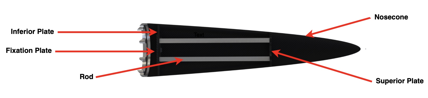
¶ Superior plate and inferior plate to Nosecone
- Both the inferior and superior plates are glued inside the nosecone
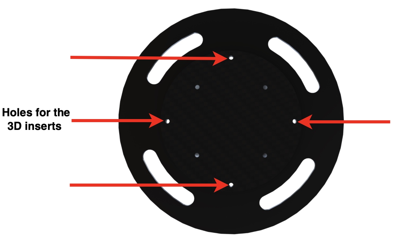
¶ Fixation plate to Inferior plate
- 3D inserts are located in the squared extrusion holes
- Screws hold in place the fixation plate to the inferior plate
¶ Rods to plates
- The 4 rods of the payload bay are glued to the plates on both extremities
¶ Payload to Payload-Bay
- Payload is inserted from underneath the inferior plate's square hole and pushed all the way up against the superior plate
- It is then held in place by the fixation plate
- Additional screws inside the square hold the payload
¶ Plates to Nosecone
- Plates are glued inside the nosecone
- Glue is applied in the "groove" of the plates so the glue doesn't spill inside the nosecone
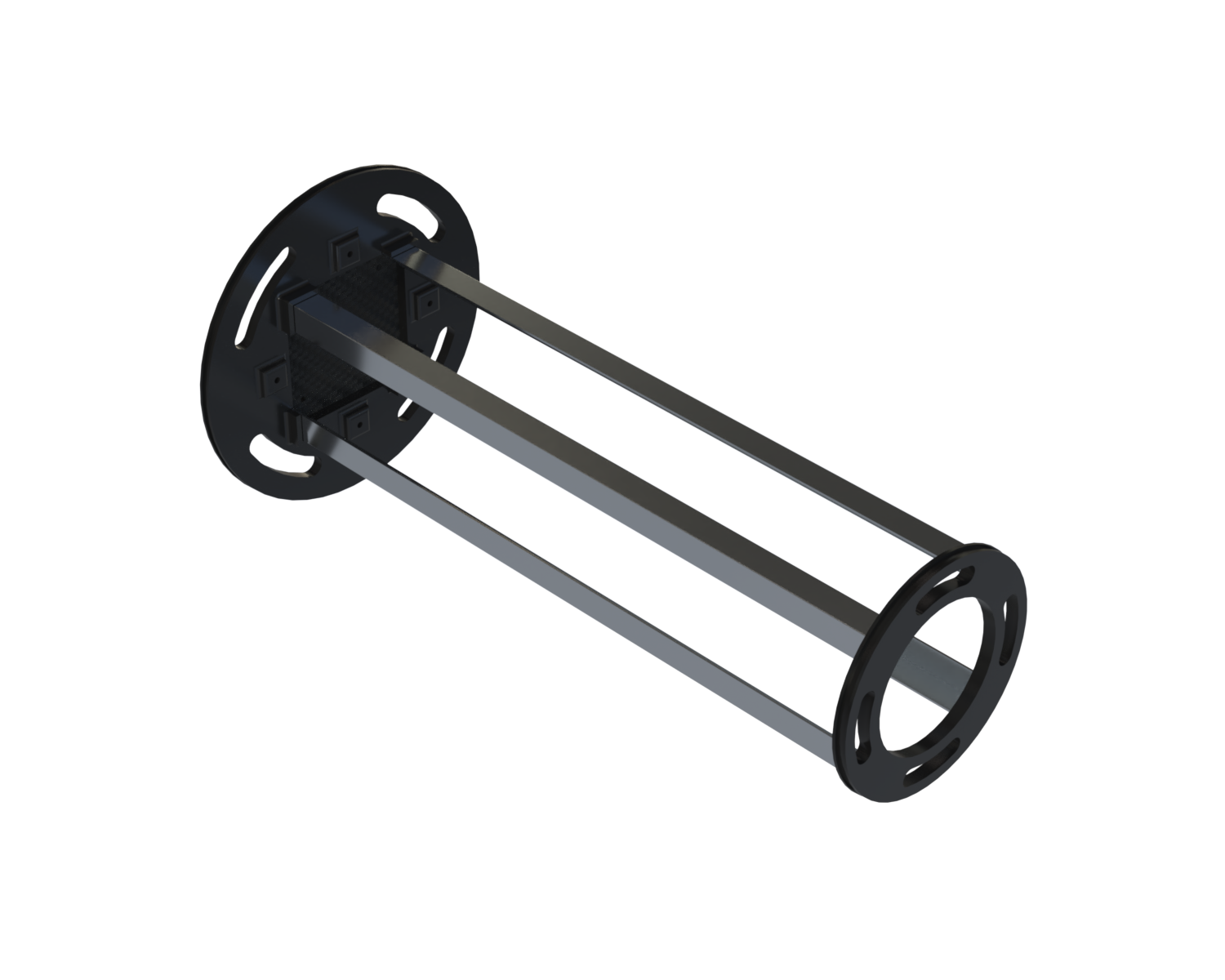
¶ Pictures of the assembly
-
Isometric view
-
Front view
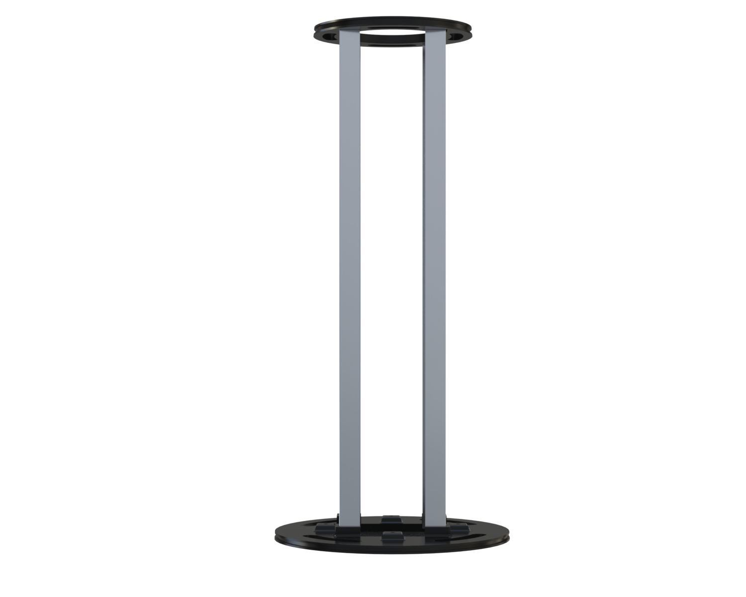
-
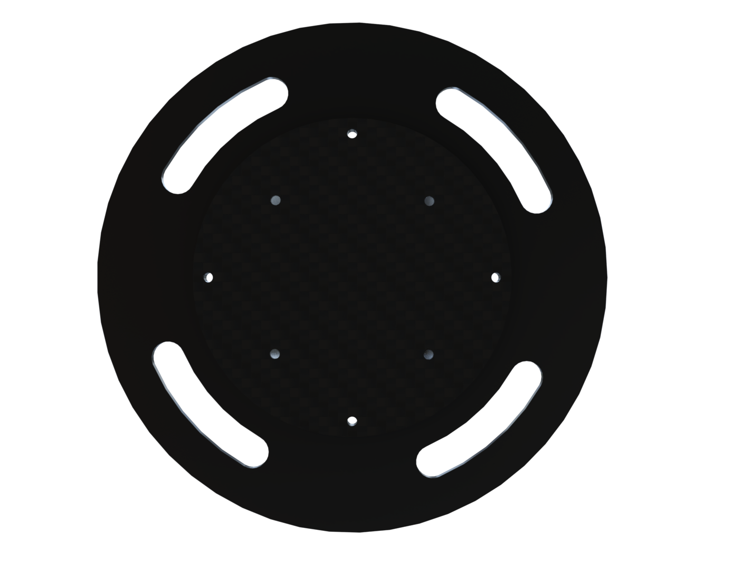
Bottom view
¶ Interface ST - PL Camera
¶ Enumerated Interfaces
** A Remplire **
¶ Pictures of the assembly
Both of the camera should be connect to the aerocover.
The aerocover must be hermetic so the modules have to be attached to the plumbing cover but also at the airframe
Cameras need to be connected with avionics bay. Extra space must be provided for a cable from segment 3 to segment 6
¶ Pictures of the aerocover
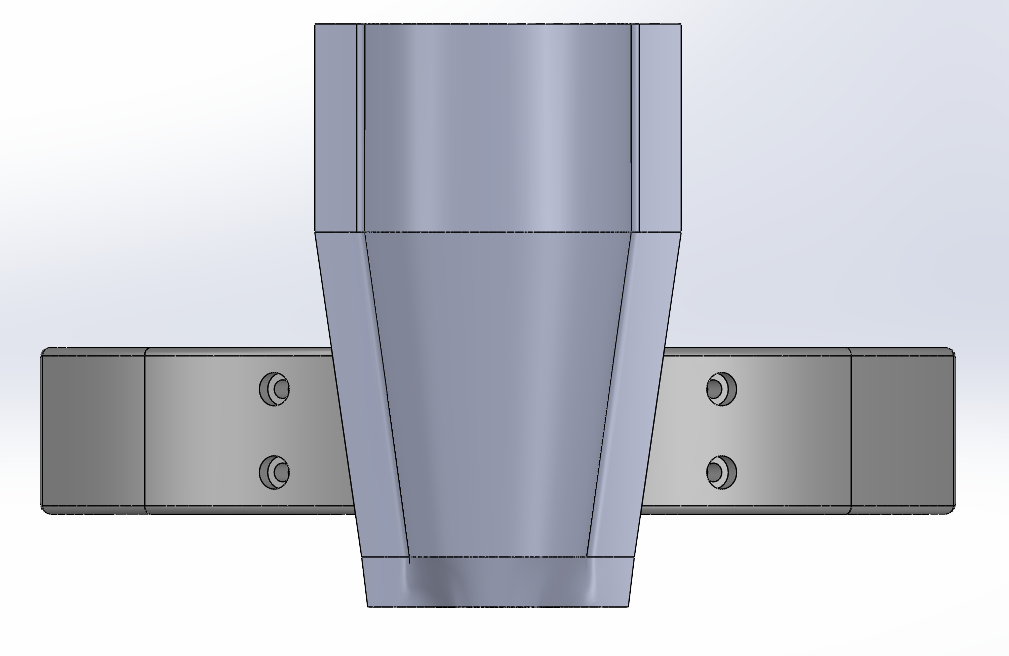
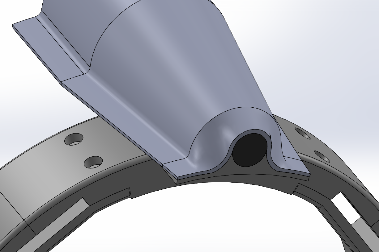
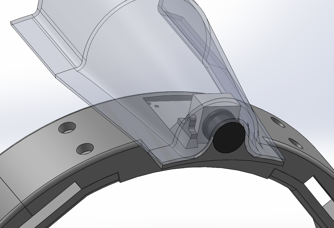
¶ 3 pictures of the bottom part of the aerocover
![Bottom_aerocover_1.png]
(/technics/Competition/2024 - Project Firehorn/Structure/Documentation/render/Novembre 2024/Payload Bay/[Bottom_aerocover_1.png] =300x)
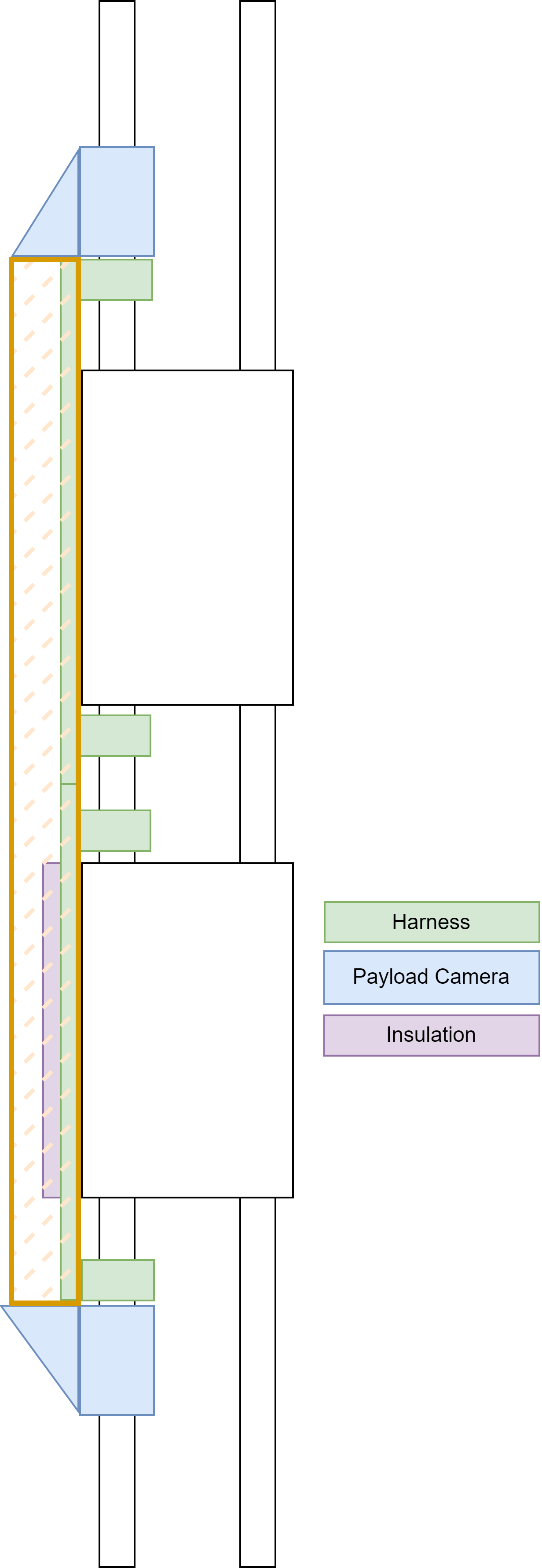
This version is a kind of pipe clip. The idea is to design a module of 2 clips that would clip onto the G1/2 and G1/4 pipes at certain points under the plumbing cover, and which would only allow the electrical lines to be guided. The PC would then be attached not to the harness, but directly to the aifraime and ABR of PB, and to the MPS of MB and EB. Insulation would no longer be necessary, and the weight of the part would be drastically reduced.
The constraints to be checked are:
- Be able to ensure that the clips are static and have all degrees of freedom blocked even under the effect of rocket vibration.
- Do not slide along pipes
- Take up as little space as possible for the Plumbing Cover
To do this, they will be shaped to fit the airframe, and a tightening/clamping system using M2 screws along the pipes will be used to hold them in place.
- This Piece can be clamped with an M2 on the pipe part and offers a different shape for cable management.
¶ Fixation of the Cover
With this system, it will be impossible to attach the harness and cover together. They will therefore be independent. We'll need to prepare a part to attach the Cover to the available module, i.e. an ABR, and MPS (in MidBay, EngineBay and PressureBay)
¶ Fixation of the camera
The camera parts will be fixed to an ABR in EngineBay and PressureBay by means of a junction piece. They will not be connected to the harness part. To ensure sealing, it is therefore necessary to provide a fitting system between the plumbing cover and the camera cover.
Old version (will be delete in the next days)
¶ ABR to Harness
- prototype :
(I have to redo it on Photoshop)
This is only a prototype sketch for the moment.
- They will be used once in the PressureBay and once in the EengineBay
- The attachment module for connecting ABR and the harness is attaches to the ABR from the top and connects to the harness from the bottom.
- The part with the red dot is stressed by a force P at its end.
- As the force is not yet known, we don't know what material to use. The structure to resist a moment of force created by the harness is also improvable.
¶ MPS to Harness
no design yet
same function as the abr to harness module
should be used in the midBay
¶ Harness chassi part
The chassi should be in a light material as it is not subject to much stress apart from vibrations.
It must be glued to the rocket panel and held against it by the Harness to ABR and Harness to MPS modules.
A space under the harness is provided to isolate the cables from the reservoirs using insulation or other materials.
The fixation of the plumbing cover is on the surface on the sides of the harness
All are made on it to equipe some module to incorporate cable management parts
We must guarantee that the chassi will not detach from the modules connecting it to the rocket, nor disassemble if it is made in several parts.
¶ Acces Pannel
The acces pannel should be easy to remove even under the aerocover
They must have holes to pass the ABR and MPS to Harness module through.
¶ Isolation
The aerocover and harness are designed so that there is no flat surface for the cables to run directly against the air frame.
This is to avoid any contact with the tanks holding OxL at -183°C. In the space between the 2 surfaces, the question of whether to use an insulating material or to leave air in the space is a matter for study.
λ Air = 0,024W/mK
(source : https://www.isolsuisse.ch/wp-content/uploads/2020/09/2020_08_NT_Isolation_technique_du_batiment_FR.pdf )
¶ Relevant Requirements
- 2024_C_SE_ST_NOSECONE_REQ_02 Nosecone declaration of purpose
The nosecone of the LV shall host the PL. - 2024_C_SE_ST_NOSECONE_REQ_05 PL integration
The nose cone shall be able to integrate a PL of the CubeSat standard [RD01] within the 3U format. - 2024_C_SE_ST_AEROCOVER_REQ_06 Aerocover camera integration
The aerocover shall incorporate a camera on either extremities. - 2024_C_SE_ST_AEROCOVER_REQ_07 Aerocover camera integration 2
The design of the camera to be integrated in the aerocover shall be given by PL.
- 2024_C_SE_PL_ACOUSTIC_LEVITATION_EXPERIMENT_07 Volume
The payload shall fit within a [50]x[10]x[10]cm volume. - 2024_C_SE_PL_ACOUSTIC_LEVITATION_EXPERIMENT_08 Structure
The payload shall include its own internal or external structure. - 2024_C_SE_PL_ACOUSTIC_LEVITATION_EXPERIMENT_12 Payload assembly
The payload structure shan't be inextricably connected to other rocket components than the payload supporting structure. - 2024_C_SE_PL_STRUCTURAL_SENSORS_REQ_01 Declaration of purpose
Structural sensors shall be integrated inside the launch vehicle to record the time history of loads encountered during flight. - 2024_C_SE_PL_STRUCTURAL_SENSORS_REQ_02 Integration location
The sensors shall be located in a location where they are able to record the loads encountered by the internal structure of the launch vehicle. - 2024_C_SE_PL_STRUCTURAL_SENSORS_REQ_03 Integration location 2
The sensors shall be located in a location where they are not interfering with the operations or the assembly/disassembly of other components of the launch vehicle. - 2024_C_SE_PL_CAMERAS_REQ_01 Declaration of purpose
Cameras shall be integrated into the launch vehicle to record the flight. - 2024_C_SE_PL_CAMERAS_REQ_02 Camera locations 1
A camera shall be located at the bottom end of the aerocover to record downwards during flight. - 2024_C_SE_PL_CAMERAS_REQ_03 Camera location 2
A camera should be located at the top end of the aerocover to record upwards during flight. - 2024_C_SE_PL_CAMERAS_REQ_04 Camera location 3
A camera should be located at the top of the avionics bay to record the parachute deployment.
¶ Interface Verification Tests
¶ Weekly Updates
¶ 27.09.24 - Aerocover interface meeting ST-PL-FD
- The aerocover cross-section shall be at least 25mm x 25mm (exact dimensions TBD).
- The cameras should be fixed to the LV body and the aerocover should be assembled on top with cutouts for the cameras.
- The electronics should be inside of the LV body and attached to the internal structure (possibly to the MPS)
¶ 12.11.24 - Aerocover interface meeting ST-PL-FD
- The main topic was the camera's integration into the aerocover. There will be a camera looking radially while the second one will look down from the bottom section of the aerocover.
- However, there was a concern on the aerodynamic consequence on the rocket but a good compromise (aerodynamic/position of camera) has been found to minimize negative impact on the aerodynamics.
- The cameras will be connected to the harness with cables.
¶ 26.03.25 - Sepmech camera meeting ST-PL
The physical interface between the camera and the AV bay will be 4x M4 holes spaced 26mm x 40mm