(ADD LATER FLUID DIAGRAM)
¶ Pressurant-Bay
¶ Interface description
This section will be used throughout the development of Firehorn to track and manage the interface concerning the integration of the plumbing system in the PB.
¶ Enumerated interface
- COPV (radial fastener)
- Plumbing (if no axial fastener for the COPV)
¶ Relevant rerequirements
- 2024_C_SE_ST_PRESSURANT-BAY_REQ_01 Pressurant bay declaration of purpose
The Pressurant Bay shall host the tanks' pressurizing systems. - 2024_C_SE_ST_PRESSURANT-BAY_REQ_02 Pressurant bay length
The pressurant bay shall have a maximum length of [700]mm. - 2024_C_SE_ST_PRESSURANT-BAY_REQ_06 Length available for PR
The length available for PR contained inside the integration diameter shall be at least [650]mm. - 2024_C_SE_PR_FLUID-SYSTEM_REQ_05 Pressurant bay module dry mass
The pressurant module dry mass shall not exceed [6500]g.
¶ Cryogenic Tanks + Mid-Bay
¶ Interface description
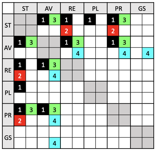
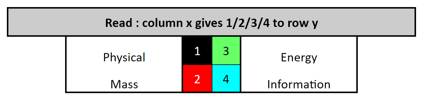
This section will be used throughout the development of Firehorn to track and manage the interface concerning the connection between the tanks and the propulsion system. Both ends of both tanks have 4 G1/2 holes and 1 central G1/4 hole.
¶ Ethanol Tank
 |
 |
|---|
¶ LOX Tank
 |
 |
|---|
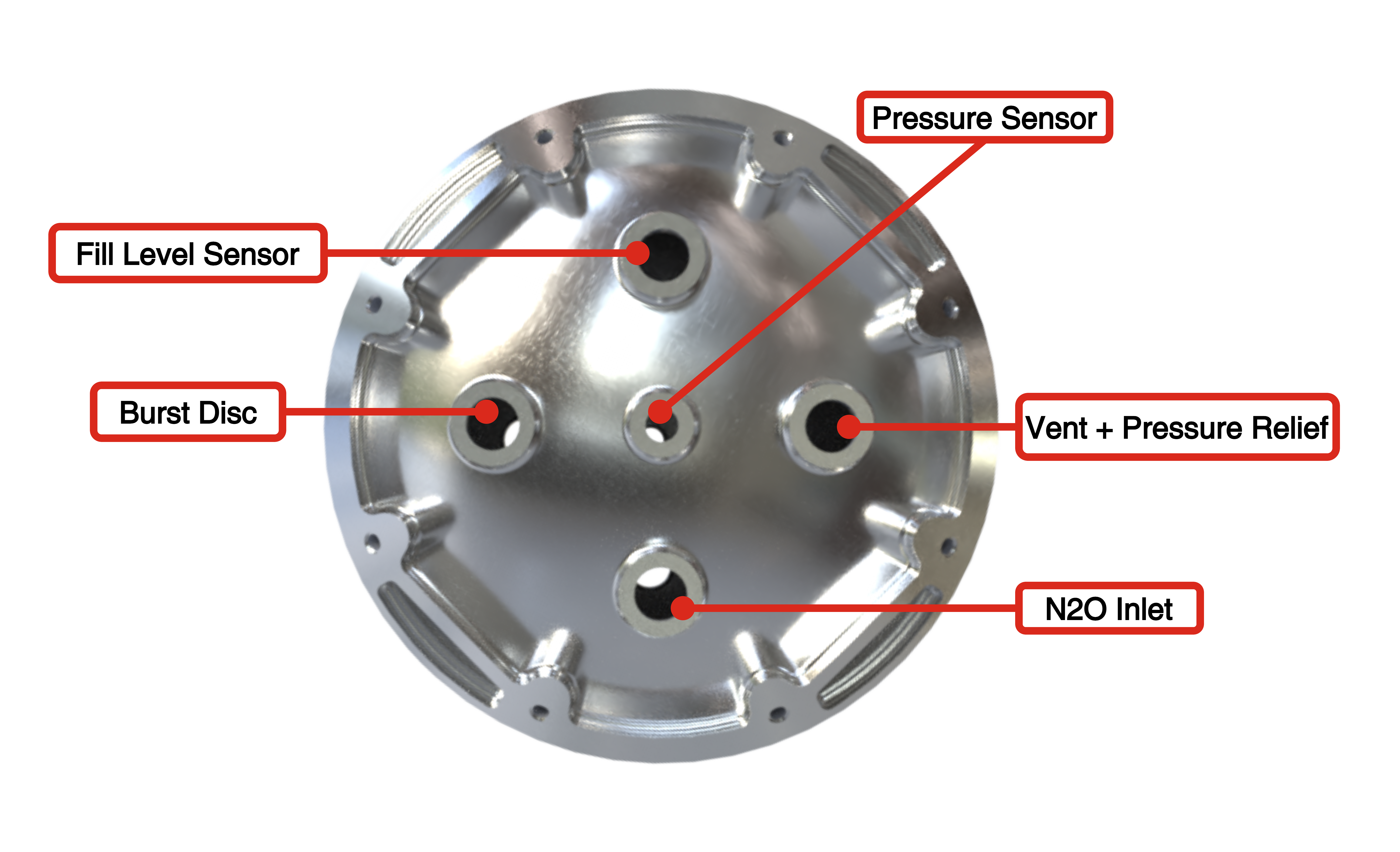
¶ Enumerated interface
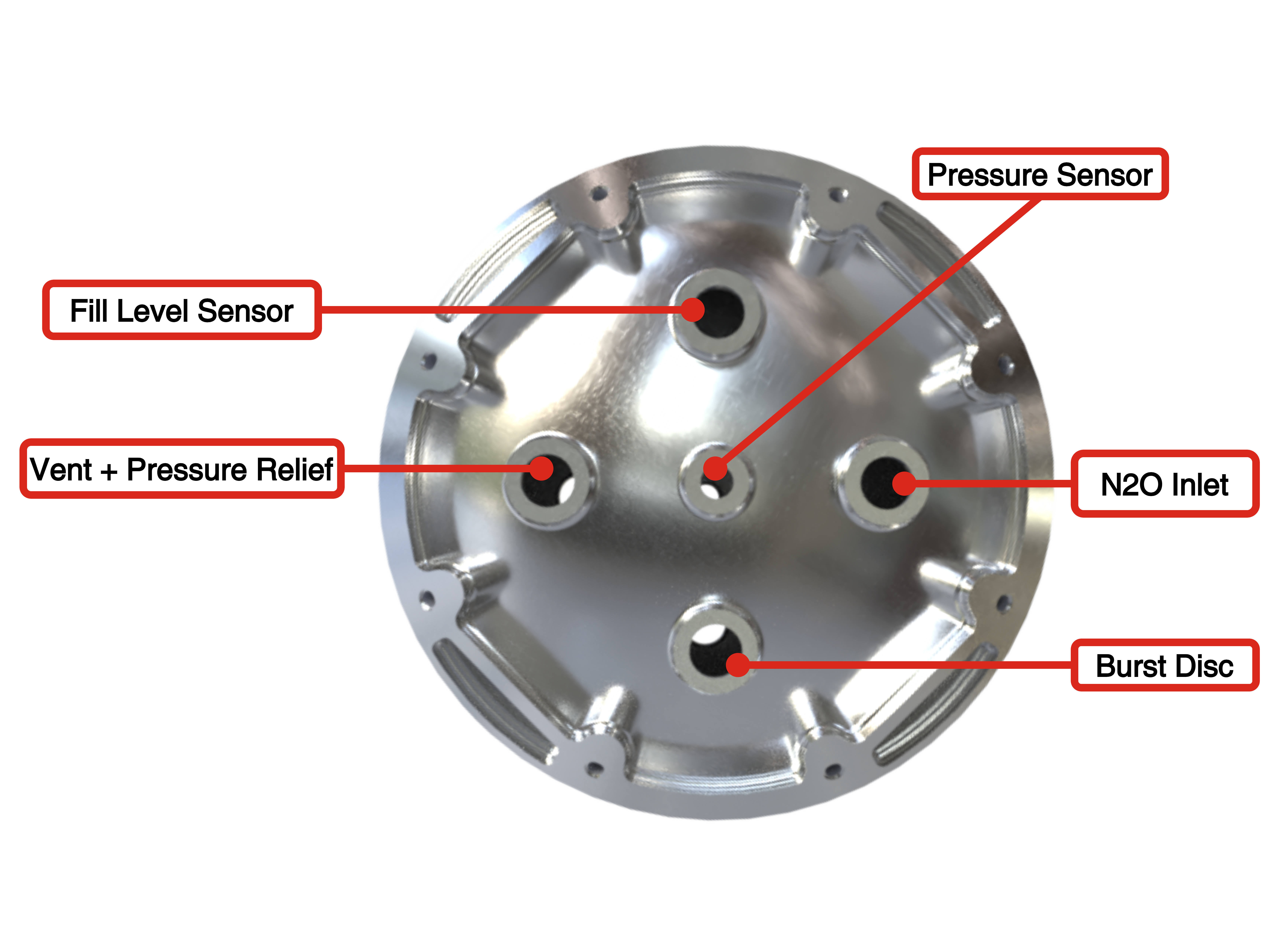
Top of Ethanol Tank
- Vent (V1) + Pressure relief
- N2O inlet + Pressure regulator
- Pressure sensor (P2)
- Fill level sensor (L1)
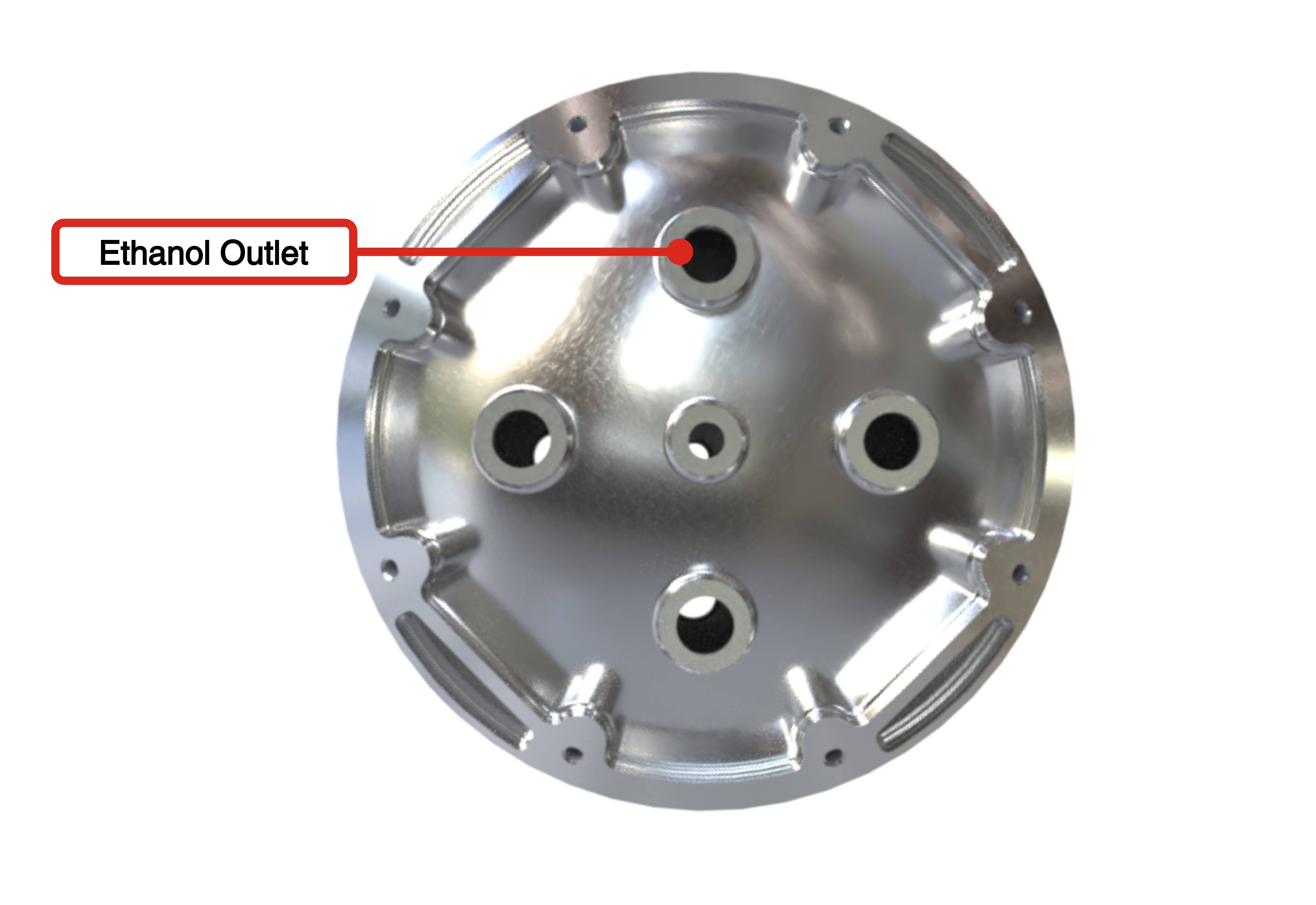
Bottom of Ethanol Tank
- Ethanol outlet
Mid-Bay
- Plumbing support
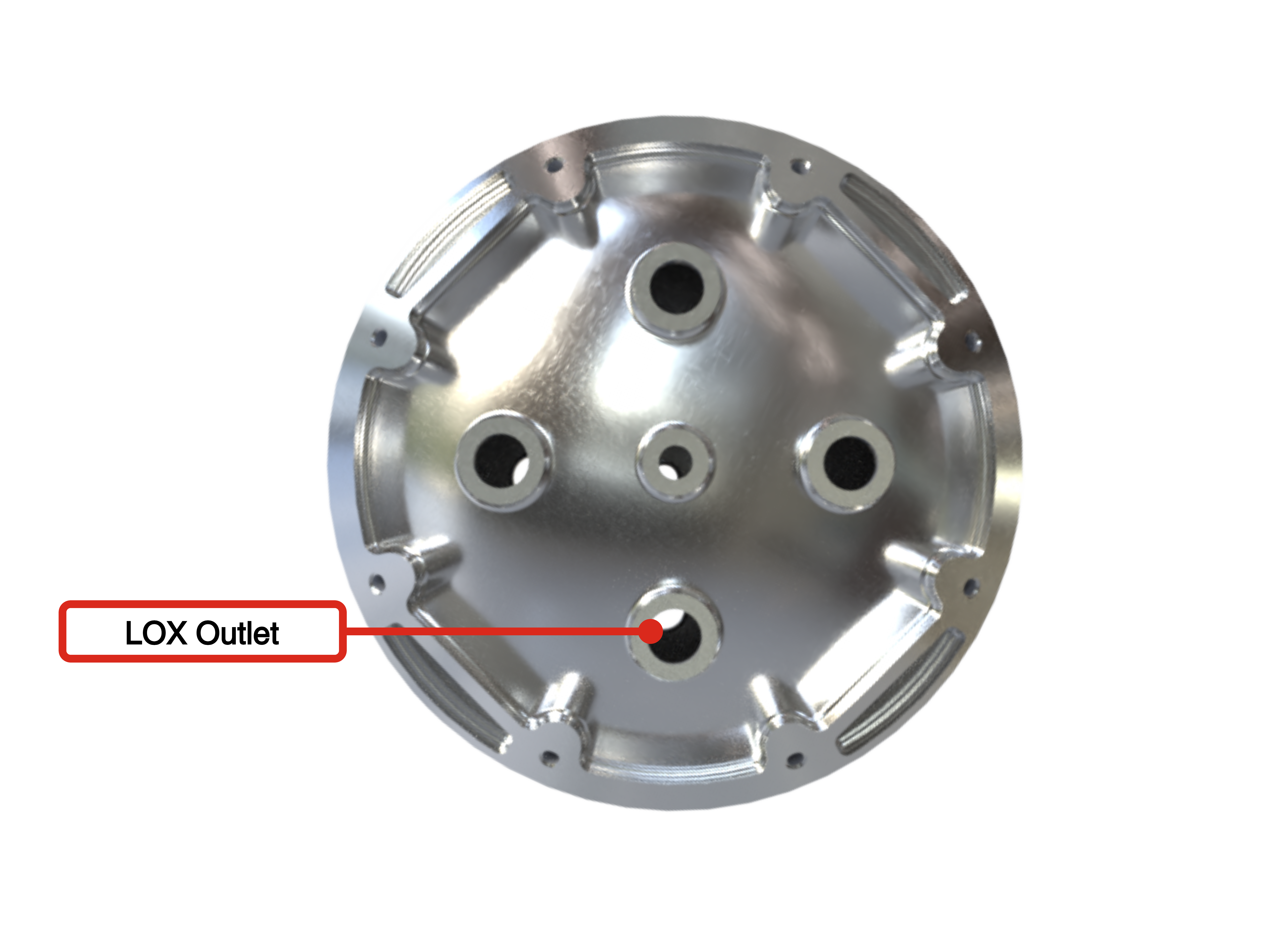
Top of LOx Tank
- Vent (V2) + Pressure relief
- N2O inlet + Pressure regulator
- Pressure sensor (P3)
- Fill level sensor (L2)
Bottom of Ethanol Tank
- LOx outlet
Aero-Cover
¶ Relevant rerequirements
- 2024_C_SE_ST_TANK_REQ_01 Tank declaration of purpose
The tank shall host the liquid oxygen or the liquid ethanol required for the LV engine. - 2024_C_SE_ST_TANK_REQ_03 Tank volume
The tank shall have an internal volume of [23][+1/-0]L. - 2024_C_SE_ST_TANK_REQ_07 Tank mass
The total mass of the tank module shall be maximum [10100]g. - 2024_C_SE_ST_TANK_REQ_13 Outside plumbing attachment
All plumbing present outside of the LV shall be firmly attached to the LV so as to whithstand all expected flight loads encountered by the LV. (External flight loads TBD) - 2024_C_SE_ST_MID-BAY_REQ_01 Mid bay declaration of purpose
The Mid Bay shall host the plumbing needed for pressurizing the lower tank. - 2024_C_SE_ST_MID-BAY_REQ_02 Mid bay length
The Mid Bay shall have a maximum length of [280]mm. - 2024_C_SE_ST_MID-BAY_REQ_05 Outside plumbing attachment
All Mid Bay plumbing present outside of the LV shall be firmly attached to the LV. - 2024_C_SE_ST_AEROCOVER_REQ_03 Aerocover length
The aerocover shall extend from the top of the pressurant bay to the middle of the engine bay. - 2024_C_SE_PR_FLUID-SYSTEM_REQ_08 Mid bay module mass
The mid bay module mass shall not exceed [2800]g.
¶ Engine-Bay
¶ Interface description
This section will be used throughout the development of Firehorn to track and manage the interface concerning the integration of the plumbing system in the EB.
¶ Enumerated interface
Plumbing fasteners
Quick disconects
- Ethanol + N2O inlets
- LOx inlet
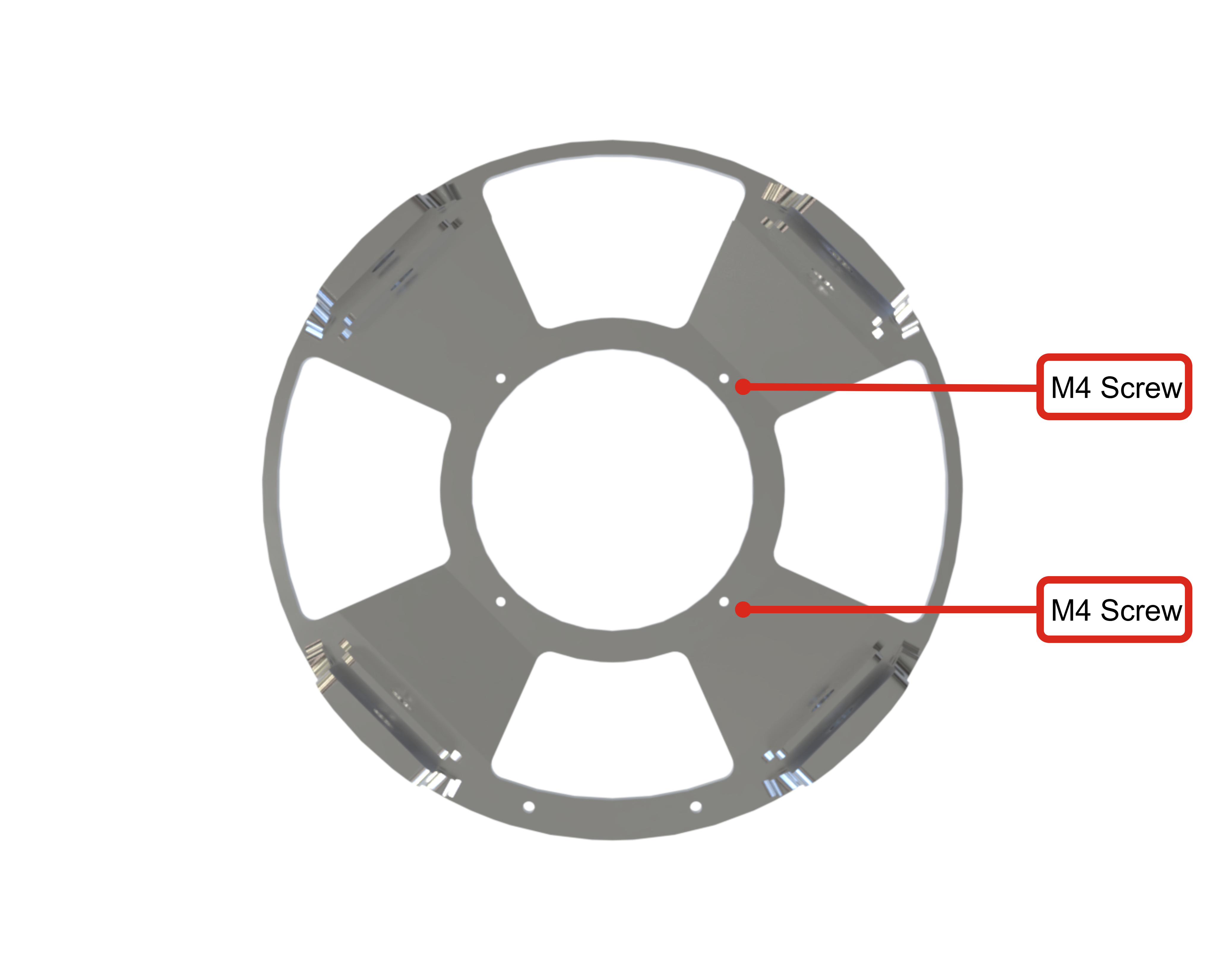
Thrust-plate
- The bottom of the thrustplate is directly in contact with the top part engine, where both surface are attached using 4 M4 screws. The screws are set from the thrustplate to the engine. (picture 1)
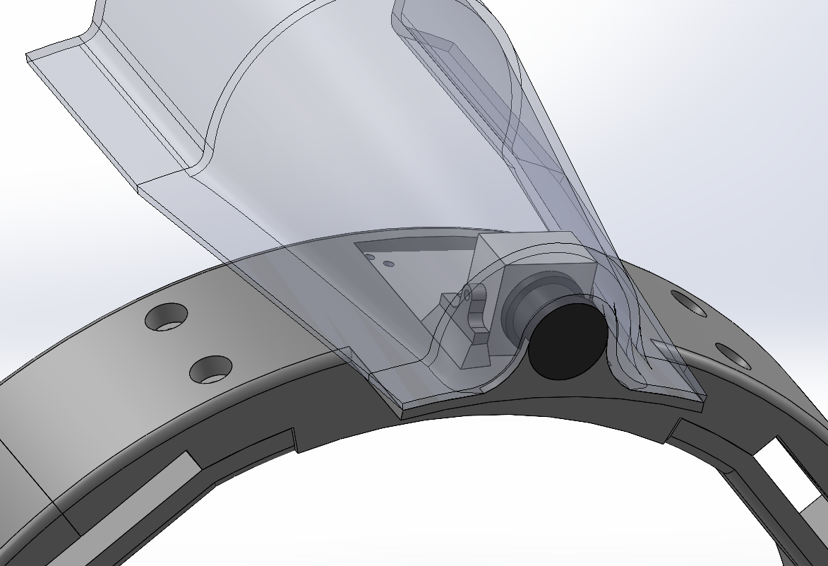
Boattail
- The exhaust shield is attached to the engine and more specifically to the nozzle using a intermidiary part that is used to lock the exhaust shield. The attachement part is fixed using 2 M4 screws, that thighten the part to the nozzle, then the exhaust shield is screwed to this attachement part to enssure that it will remain immobile. (picture 2)

In total there are 10 M4 screws (4 for the thrustplate and 6 for the Exhaust shield) used for the interface EB-PR
Attached for Camera and Aerocvover
In the Q3 quarter, the ABR of segment 3 will be used to fix the camera as well as the aerocover. For now, putting an MPS is useless because there is no longer any need to fix the current harness to the rods.
Here it is an MPS but it should be a module connecting the shelter to the Plumbing cover and the camera
¶ Relevant rerequirements
- 2024_C_SE_ST_ENGINE-BAY_REQ_01 Engine bay declaration of purpose
The Engine Bay shall host the combustion chamber, the boattail and the valves assembly located below the tanks. - 2024_C_SE_ST_ENGINE-BAY_REQ_02 Thrust plate
The Engine Bay shall transmit the thrust from the engine to the rest of the rocket through a fixed thrust plate. - 2024_C_SE_ST_ENGINE-BAY_REQ_04 Bay length
The Engine Bay shall have a bay length of [700][+/-20]mm - 2024_C_SE_ST_ENGINE-BAY_REQ_06 Inside access
The Engine Bay shall allow for a human hand to access the valves inside. - 2024_C_SE_ST_ENGINE-BAY_REQ_07 Cable access
The Engine Bay shall allow for cables coming from the AV module to be connected to the valves. - 2024_C_SE_PR_ENGINE_REQ_04 Engine bay module mass
The engine module shall have a maximum weight of [9000]g.
¶ Interface Verification Tests
¶ Weekly Updates
¶ 27.11.24 (Date)
¶ Retropesctive
- Taille rods:
Pressurant Bay 700mm
Mid Bay 280mm
Engine Bay 700mm
¶ Perspectitve
- Pressurant Bay
Julian attache COPV
No constraints on attachements' position
ABR up to fix radially COPV
ABR down to fix axially COPV
ABR down Q3 blocked by Aerocover - Tanks
Number of inlets -> 5
Types of inlets: centre G1/4, 4 others G1/2 - Aerocover
Position: start Q3 ABR down, end Q3 seg 3 MPS
Number of pipes: 1 (1/4) fom pressurant bay, passing by mid bay and ending to engine bayt ; 1 ethanol pipe from mid-bay (1/2) ending to engine bay.
Attachement of pipes: PR responsibility - ABR seg2 Q3: axial holes for filling
- MPS + Quick disconnect
Why ? Where ? Size ? -> Julian Draw.io on this LLIM - Thrust-plate
98mm diameter of B1 at interface -> (Tolerance can be the same as for thrustplate TF) - Exhaust shield