¶ title: 2023_ST_TN_A03_AB_Rings
description: Link: https://rocket-team.epfl.ch/en/rocket_ss/structure/Nordend/2023_ST_TN_A03
published: true
date: 2025-05-21T19:10:11.964Z
tags:
editor: markdown
dateCreated: 2023-07-12T08:45:18.749Z
¶ title: 2023_ST_TN_A03_AB_Rings
description: Link: https://rocket-team.epfl.ch/en/rocket_ss/structure/Nordend/2023_ST_TN_A03
published: true
date: 2024-12-30T21:17:36.044Z
tags:
editor: markdown
dateCreated: 2023-07-12T08:45:18.749Z
¶ title: 2023_ST_TN_A03_AB_Rings
description: Link: https://rocket-team.epfl.ch/en/rocket_ss/structure/Nordend/2023_ST_TN_A03
published: true
date: 2023-12-01T02:40:51.074Z
tags:
editor: markdown
dateCreated: 2023-07-12T08:45:18.749Z
¶ Anti-Buckling Ring Technical Note
¶ 1. Introduction
The internal structure of the rocket is based on four carbon-fiber rods that will sustain and withstand all the load that is transmitted through the rocket. The main goal of the AB rings is to prevent these four rods from buckling. Their auxiliary role is to ensure a secure attachment of the external panels and shell of the rocket.
¶ 2. Definitions and Abbreviations
| --- | --- |
| BL2 | Bella lui 2 |
| WH | Wildhorn |
| ST | Structure |
| ERT | EPFL Rocket Team |
| EPFL | École Polytechnique Fédérale de Lausanne |
| AB | Anti-Buckling |
| CFRP | Carbon Fiber Reinforced Polymer |
¶ 3. Design
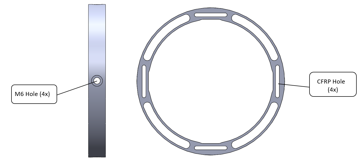
There are two distinct designs for the AB rings that will be strategically placed along the rocket :
Engineering requirements :
- 4 oblong holes for the CFRP rods
- 4 M6 screw holes
- 4 M6 nut flat surfaces
- An external diameter of 152.8mm
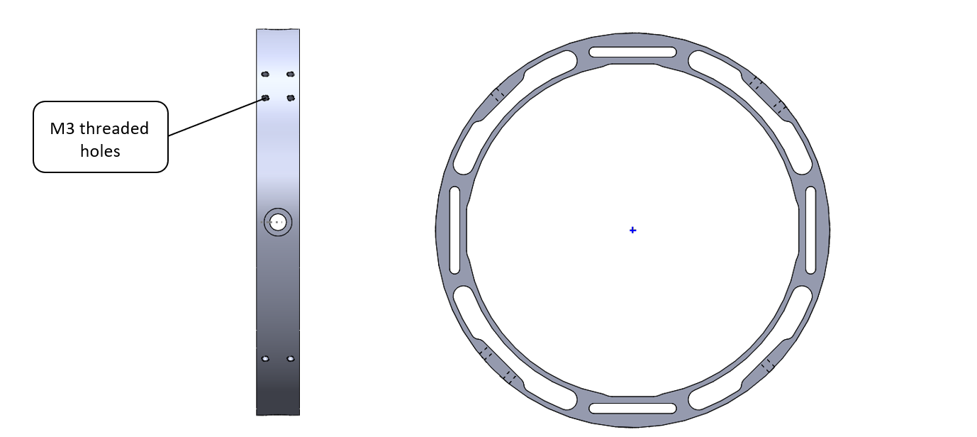
Engineering requirements :
- 4 oblong holes for the CFRP rods
- 4 M6 screw holes
- 4 M6 nut flat surfaces
- An external diameter of 152.8mm
- 6 M3 threaded holes to hold the external panels and antennas.
¶ 4. Simulations
Simulations on our CFRP rods show that the resistance force of the AB needed to prevent ONE rod from buckling is 200N. Taking into account a security factor of 2 , we assumed that every rod applied a force of 400 N on every AB ring, and more specifically on the inner surface of the CFRP hole (this of course is dictated by the direction of buckling).
The simulation cycle was quite simple, it consisted of an iteration of a topological test, followed by a static FEM simulation that eventually led to the final designs mentioned above.
The goal was simple: Find the lightest design that can withstand the loads while ensuring machinability.
The cycle initially started with a basic ring shape as shown in the picture .
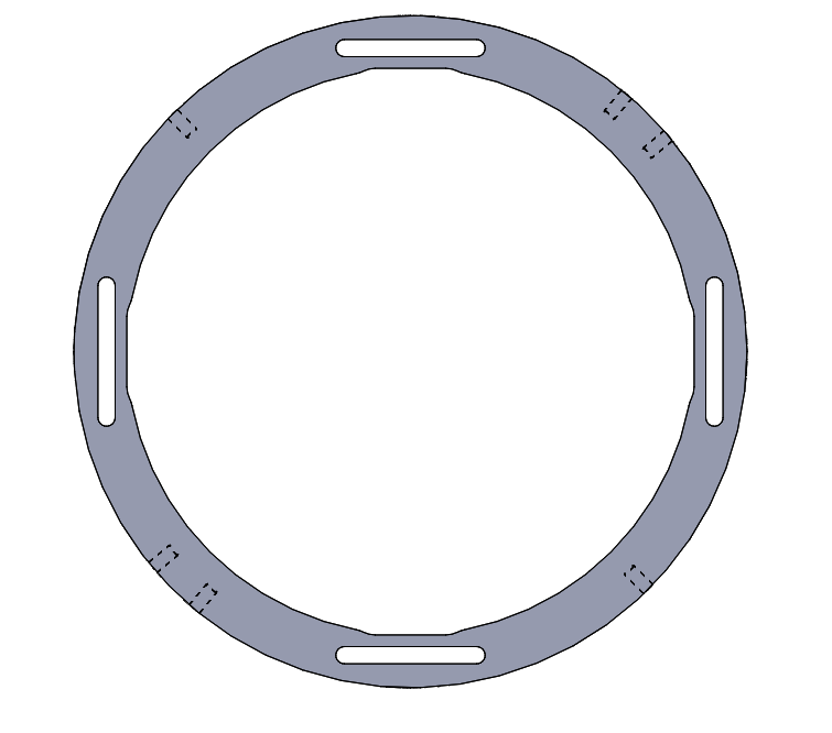
Initial shape of AB ring (design #2)
¶ 4.1. FEM Simulations
The static FEM were done using Solidworks. A sample of the static FEM tests have been presented in the complementary pictures.
Please note a couple of remarks :
- We realized during the design phase that the AB ring was largely able to withstand and resist the required loads and that the part was not critically under load. This lead to the trivial decision of using Aluminum 6082-T6, a well known alloy used throughout the launch vehicule.
- We initially did the test on the AB ring alone, however we realized that this is not representative of reality as the load imposed in that case was not distributed properly on the surface. So we opted to an assembly of the ring with a mini CFRP rod and to simulations on this assembly configuration. The results obtained were much closer to what we expected to see in real life.
- The symmetry of the AB ring allowed us to split it into 4 which made the tests significantly easier
- FEMs here under are for the design #2.
¶ FEMs inputs summary :
| Software | Simulation Type | FoS | Material | Material Yield Sress [MPa] | Simulation Force [N] |
|---|---|---|---|---|---|
| Solidworks Simulation | Static - isotropic | 2 | Al 6082 T6 | 250 | 400 |
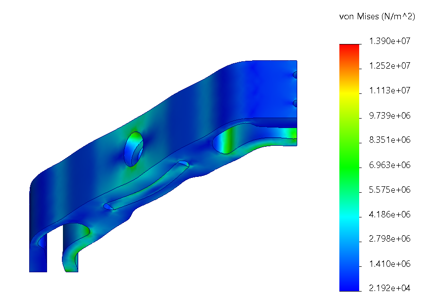
Maximum stress is around 100 [MPa], even if it is far away from the elastic limit, it was chosen to keep the aluminium under 50% of its elastic limit, to favorise launch vehicle rigidity.
Maximum stress is around 100 [MPa], even if it is far away from the elastic limit, it was chosen to keep the aluminium under 50% of its elastic limit, to favorise launch vehicle rigidity.
¶ 4.2. Topological optimisations
The topological tests were also done on Solidworks simulation. A sample of the topological tests have been presented in the complementary pictures.
Please note a couple of remarks :
- After we finished with the topological tests we realized that the design converges to a design that is very similar to that of BL2 AB ring.
- A few conditions were imposed on some critical surfaces and geometries to ensure they are preserved during simulation.
Small holes and geometries were ignored due to milling machine manufacturing constraints.
Small holes and geometries were ignored due to milling machine manufacturing constraints.
¶ 4.3. Final results and comments
After a couple iterations, the results showed that the maximum stress was considerably smaller then the yield stress of the material. Thus a lot of material could be removed, leading us to going from an initial mass before optimization of 210 g (for the initial basic design) to 120 g for design #1 and to 130g for design #2.
¶ 5. Technical Drawings
These anti buckling rings were produced outside of ERT workshops, in Komax's workshop. We will detail here under the different technical drawings sent to the workshop.
The technical drawings are also available in pdfs under the following drive folder.
No production procedure was written for this part as it was produced outside of ERT's workshop and consist of simple milling steps.
¶ 6. Placement along the rocket
Depending on the arrangement of panels and taking into consideration the modular 3d printed rings, the AB rings were placed strategically along the rocket as shown below :
Position of the AB rings along the rocket