¶ title: 2023_ST_TN_E02_Separation_Mechanism
description: Link: https://rocket-team.epfl.ch/en/rocket_ss/structure/Nordend/2023_ST_TN_E02
published: true
date: 2025-05-21T19:11:54.798Z
tags:
editor: markdown
dateCreated: 2023-08-16T15:11:27.557Z
¶ title: 2023_ST_TN_E02_Separation_Mechanism
description: Link: https://rocket-team.epfl.ch/en/rocket_ss/structure/Nordend/2023_ST_TN_E02
published: true
date: 2024-12-30T21:18:03.234Z
tags:
editor: markdown
dateCreated: 2023-08-16T15:11:27.557Z
¶ title: 2023_ST_TN_E02_Separation_Mechanism
description: Link: https://rocket-team.epfl.ch/en/rocket_ss/structure/Nordend/2023_ST_TN_E02
published: true
date: 2024-12-04T20:11:44.108Z
tags:
editor: markdown
dateCreated: 2023-08-16T15:11:27.557Z
¶ Separation Mechanism Technical Note
¶ 1. Introduction
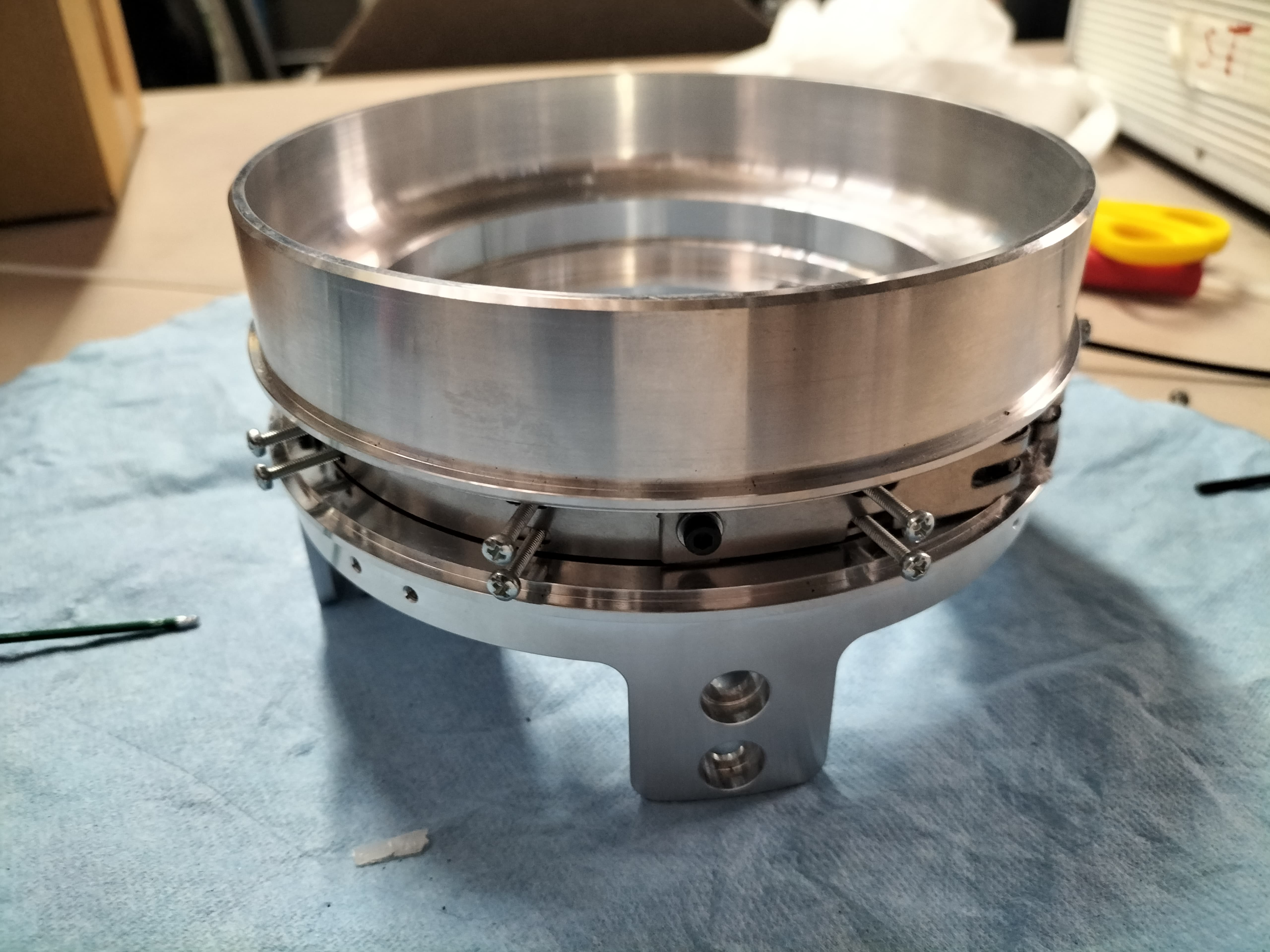
Nordend separation mechanism (SM) is based on a design similar to the previously flown on BL 2 and Wildhorn rockets. The mechanism is, in fact, based on two rings kept together by a set of clamps tightened by a steel clamp band (CB). The CB is tighten via a screw and kept together by a spliced dyneema loop on the opposite side of the launch vehicle (LV). When separation is needed (first event) the Dyneema loop is melted via a Nickel-chrome wire heated by joule effect and the CB detach from the rings allowing separation of the two LV segments. The overall design of this mechanism was the subject of an Erik Uithoven semester project that can be find under request at the following link: SM Semester Project Report
¶ 2. Reference Documents
| Ref | Description | Doc. ID | Issue |
|---|---|---|---|
| [E02] | Separation Mechanism Production Procedure | 2023_ST_PP_E02_SEPARATION_MECHANISM | 2023 |
| [E02] | Separation Mechanism Assembly Procedure | 2023_ST_AP_E02_SEPARATION_MECHANISM | 2023 |
| [E02] | Separation Mechanism Test Report and Procedure | 2023_ST_TRP_E02_SEPARATION_MECHANISM | 2023 |
¶ 3. Definitions and Abbreviations
| --- | --- |
| FoS | Factor of safety |
| FEM | Finite element method |
| ST | Structure |
| LV | Launch Vehicle |
|SM | Separation Mechanism |
|BL 2 | Bella Lui 2 |
|CB | Clamp Band |
¶ 4. Design
¶ 4.1. Requirements
Engineering requirements :
- Keep together two rocket half until first event
- Allow fast separation of the LV half
- Be as simple and fast as possible to be assembled and positioned
- Provides anchoring points for the shockplate
¶ 4.2. Design Methodology
The SM is quite similar to the one used on BL 2 LV in size and design. Here are some major modifications introduced to the design.
Design upgrades :
- Clamps material switched from steel to Al -> No Ematal treatment needed on rings.
- Clamps attached to CB via screws.
- CB-Rings surface angle reduced from 30° to 20° for a better CB tension to load transformation.
- CB assembled via screws instead of rivets allowing disassembly for integration/exchange of a spliced Dyneema loop. In the previous mechanism, a knot was used but, above a certain value of T, it began to unravel.
- New Aerocover design (Not detailed in this document because designed accordingly to first integration test results (see 2023_ST_TRP_G02).
¶ 4.3. Design Overview
¶ 4.2.1. Design Specifications
| --- | --- |
| Height | 88.2 [mm] |
| External Diameter | 157 [mm] |
| Internal Diameter | 117 [mm] |
| Weight | 0.9778 [kg] (Aerocover excluded)|
| Material | Al 6082 T6 (Rings and clamps)|
| Material | Spring steel 1.4310 (CB) |
¶ 4.2.1. Annotated Renders
Al the parts are described in the production procedure.
¶ 5. Load Evaluations
The analysis of the loads on the mechanism is done in 3 main steps:
- Step 1: Maximum bending estimation at mechanism location.
- Step 2: Maximum stress evaluation on clamps-ring contact surface (normal to surface).
- Step 3: CB Tension evaluation.
The Matlab code used for those estimation can be found at the following link: SM Matlab Code
A Traction component due to LV deceleration is also added to the Matlab computations but it is estimated to be less significant than the stress generated by bending.
¶ 5.1. Bending
The bending estimation is done considering the same parameters for the “spaghetti test” used by Erik Uithovenin his project (2g max acceleration with FoS = 2). The assumption is that all the mass is concentrated in the central LV longitudinal axis and that the rocket can be considered as a rigid beam.. This time, instead of using a Matlab computation considering every module mass and distance from the SM and CM (mass uniformly distributed for each module), a different approach is used. Having a sufficiently complete CAD of the LV the problem is solved using this data. The bending moment generated by each half of the LV (below and over the SM) is considered separately. The bending is Calculated using the following formula:
One component is found considering only the mass of one half of the rocket concentrated at his CM (found on CAD also), the other component is found considering the other half. The Two values are then summed to find the total bending. This approach can’t be used for an estimation of the bending moment on all the rocket length, but it’s considered to give more precise results at the SM location.
¶ 5.2. Pressure on CB-ring contact surface
For an estimation of the normal load on the clamps first the second moment of inertia of the clamp in the x-y plan is found ad:
Being n the number of clamps.
Assuming all the clamps homogamically distributed on the surface. This allows to find the maximum pressure load in the Z direction as:
This load is then divided by the cosine of the clamps-rings contact surface angle to find the value of load needed normal it and to use for FEM simulations.
¶ 5.3. Tension
From the previous found values we can find the tension needed in the clamps band to ensure that such a load is applied when tightening the mechanism via the screw. This tension can be fund using the following equations:
With alpha being the contact angle and mu the Al-Al friction coefficient (0.2 is used).
The resistance to the traction of the clamp band is simply verified using Hooke's law and taking A as the smallest section area of the clamp band.
¶ 5.4. Results
| Value | Unit | |
|---|---|---|
| M | 555 | [Nm] |
| I_tot | 1.326 *10+6 | [mm4] |
| Sigma Normal | 29.6 | [MPa] |
| T | 1290 | N |
¶ 6. Simulations
¶ 6.1. FEM Simulations
¶ FEMs inputs summary :
| Software | Simulation Type | FoS | Material | Material Yield Stress [MPa] | Poisson's ratio |
|---|---|---|---|---|---|
| SolidWorks Simulation | Static | 2 | Al 6082 T6 and Spring steel 1.4310 | 250 and 1300 | 0.33 and 0.3 |
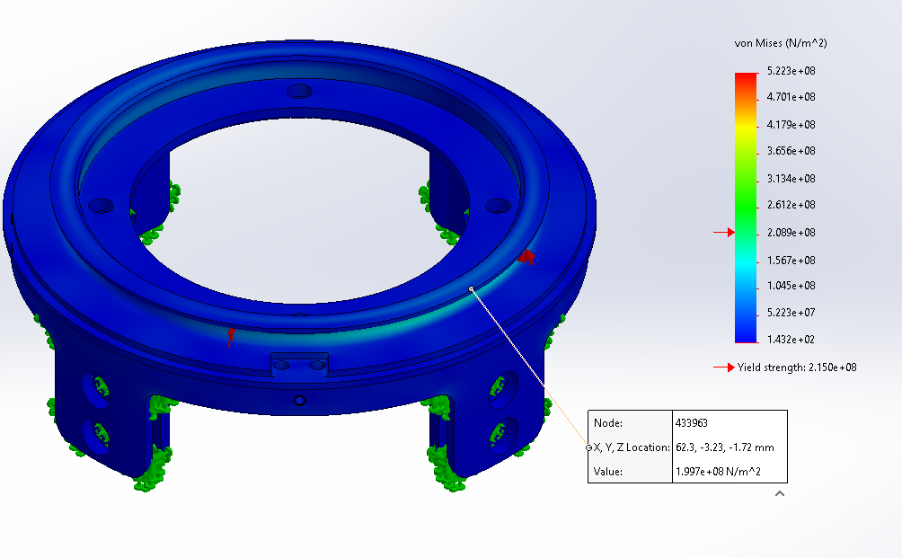
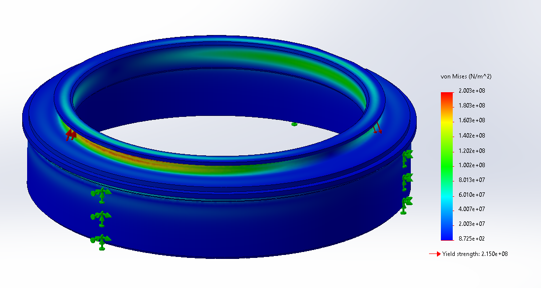
¶ 6.1 Rings simulations :
The complete Geometry of the rings is used.
The rod's attachment point (lower ring) and the glues surface (ring) are set as fixations surfaces.
A load of 30 MPa is applied normal to the clamp-ring surface. This load is not equally applied on all the surface, in fact, this value is multiplied by the cosine of the angle of application on the circular surface (Cylindrical coordinates). This allows to simulate a bending type load wit a value of 30 MPa on one side of the ring and a value of - 30 MPa (traction) on the other side.
¶ 6.1 Clamps simulations :
This simulation is done on one half of a clamp with a portion of CB behind it.
No completely fixed point are used.
A Roller/slider condition is applied to the CB edges.
A symmetry condition is applied to all the assembly at the cutting surfaces.
A load of 30 MPa is applied normally and uniformly to the clamp-ring contact surface (overestimation).
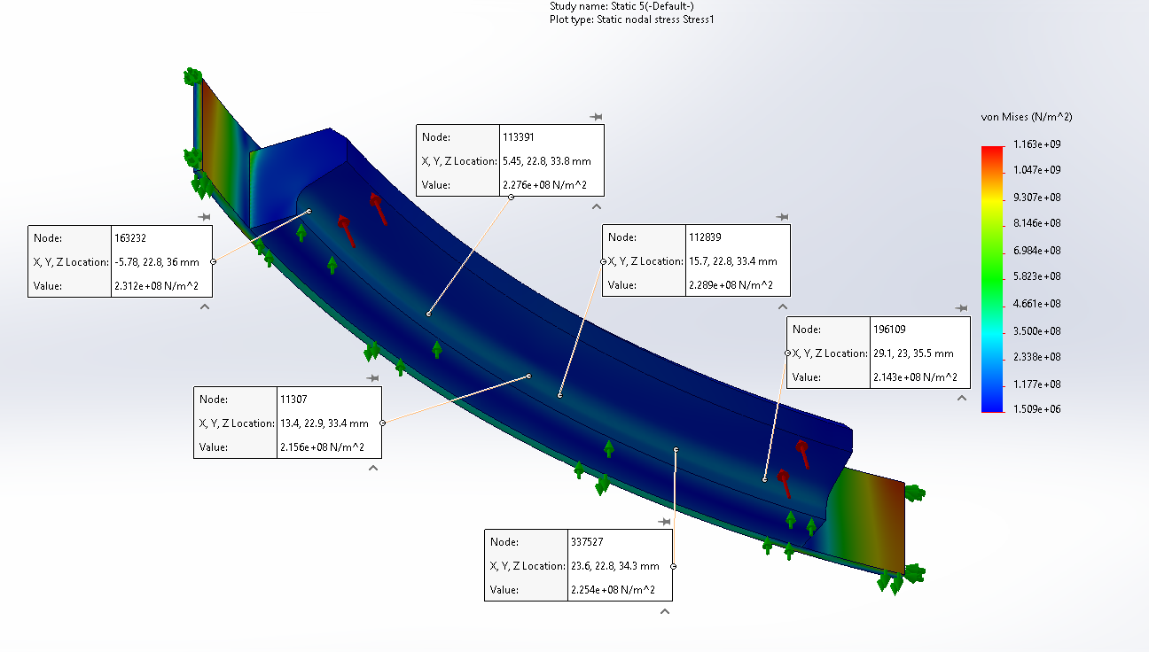
As we can see, in the clamp, simulations show that we always are below the Al 6082 T6 yield.
¶ 7. Conclusion
The final results show the feasibility of this type of mechanism. All the parts design and production procedure are described in the SM Production procedure document (2023_ST_PP_G02). During the test campaign an aerocover design will be also designed.