¶ Introduction
This page is the Design Justification File (DJF) for the Hall thruster channel. The channel is where the injected fuel (in the form of gas) gets ionised and propelled out via electromagnetic forces.
¶ Definitions and Abbreviations
- DJF : Design Justification File
- ERT : EPFL Rocket Team
- HET : Hall Effect Thruster
- CAD : Computer Assisted Design
¶ Applicable and Reference Documents
- 2025_H_PC_P3_CHANNEL_CAD HET CAD Models
- 2025_H_SE_PC_TS_THRUSTERS_P3 HET design requirements
¶ Relevant Knowledge Needed
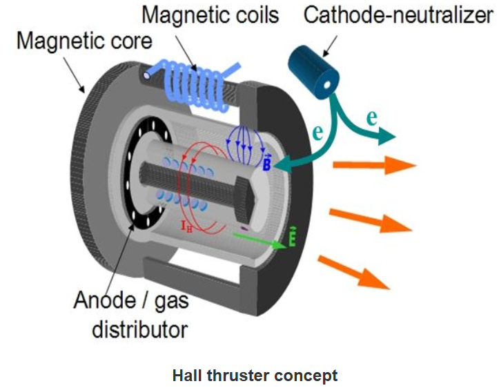
The channel is where the injected fuel (in the form of gas) gets ionised and propelled out via electromagnetic forces. A schematic of the HET channel is shown below (derived from PPPL webpage). As per the diagram, we call the direction of the electric field E as axial, the direction of the magnetic field B as radial, and the direction of the Hall current IH as azimuthal.
The neutral gas, most commonly Xenon (Xe) (although Krypton (Kr) and Argon (Ar) can also be used, but to lower efficacy and worse performance), is injected at the anode. At the same time, electrons are expelled out of the cathode close to the exit of the channel, and proceed to move towards the anode (to close the current loop). Due to the presence of an electric and magnetic field at the exit of the channel, the resulting E cross B field causes the electrons to precess in the azimuthal direction, slowing their movement towards the anode and trapping them at the exit. This is the so-called Hall current IH. The neutral gas fuel injected from the anode travels along the channel axially until they get ionised by the trapped electrons (Hall current) near the exit. Due to the axial electric field, the now positively charged ions get ejected from the channel at high speeds courtesy of the electric field.
Note that the E cross B field does not trap the positive ions due to the big Larmor radius of the positive ions. It only traps the electrons due to the small electron Larmor radius. Since the Larmor radius of each species depends on the strength of the magnetic field, which in turn depends on the current in the magnetic coils, the latter must be tuned accordingly.
- Electric propulsion textbook for reference Fundamentals of Electric Propulsion: Ion and Hall Thrusters
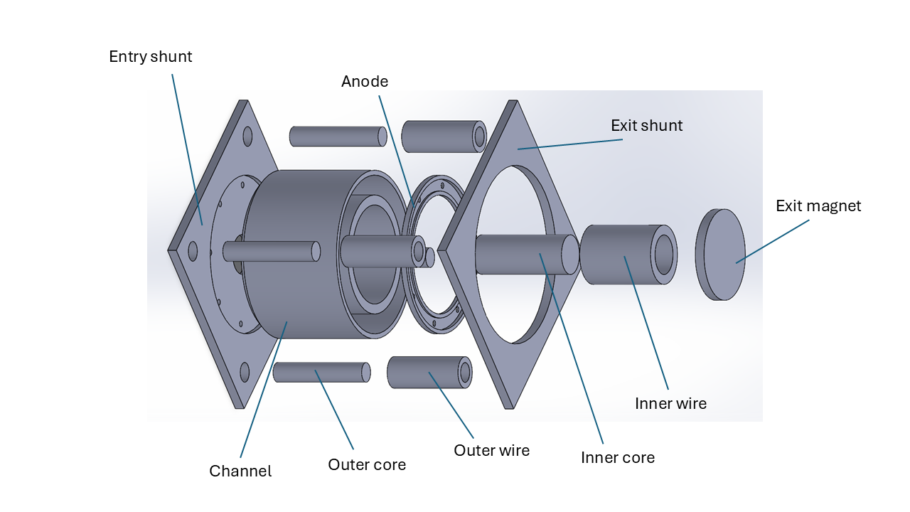
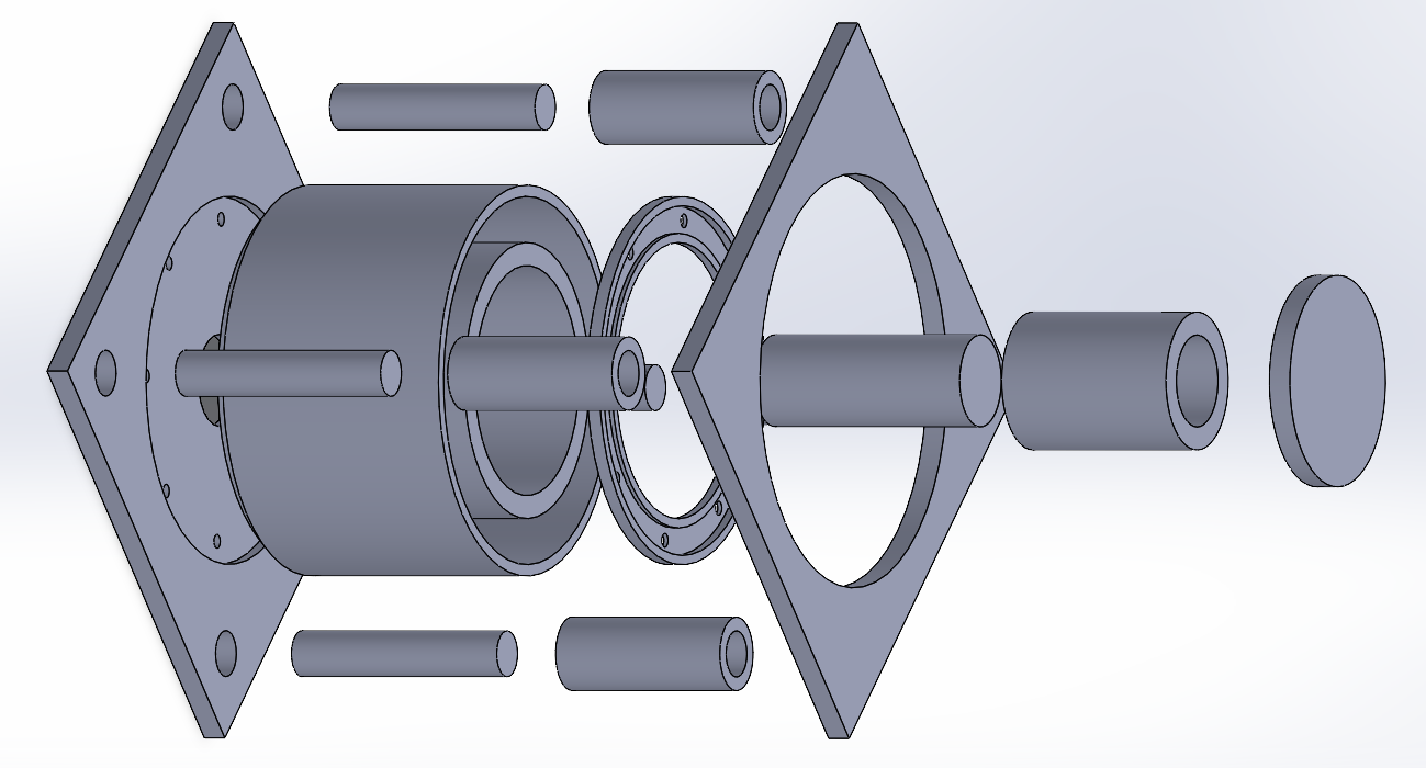
The main components of the HET CAD model are shown in the schematic below. Although the CAD models shown changes depending on the version, the number of components and component names do not.
¶ Design Options
The HET channel design follows the physical requirements laid out in 2025_H_SE_PC_TS_THRUSTERS_P3. The two CAD models shown here, as well as their specifications are available in the following Google Drive page.
- 2025_H_PC_P3_CHANNEL_CAD HET CAD Models
The 331000 CAD model is the base version of the HET channel design. Its simplicity means that it is good in simulations, but is not realistic because of the absence of places for screws and nuts to hold the entire model together. Also, it is not simple to manufacture compared to later models. Apart from being the preferred simulation model, 331000 serves as a base model on which more realistic models 332000 and 333000 are improved upon. This means that the external dimensions in 332000 and 333000 models are the same as 331000, at in milimeter length. One should refer to 331000_Specifications.pdf for the dimensions and specifications of the main components of 331000.
Good and simple for simulations
Not a realistic model
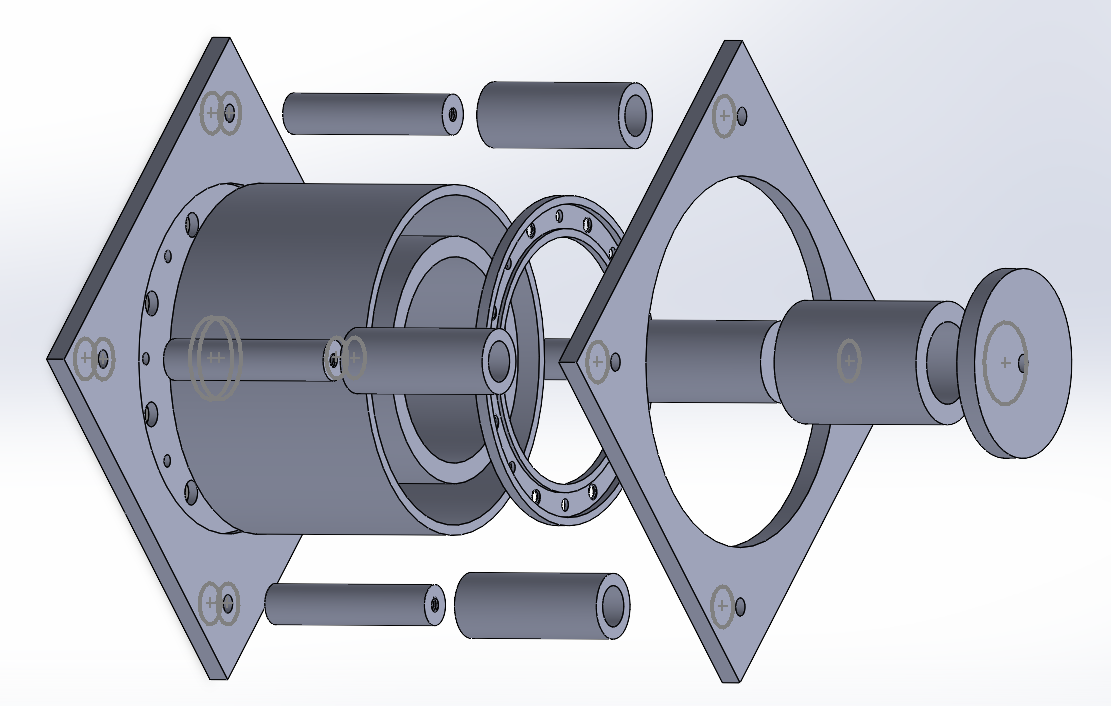
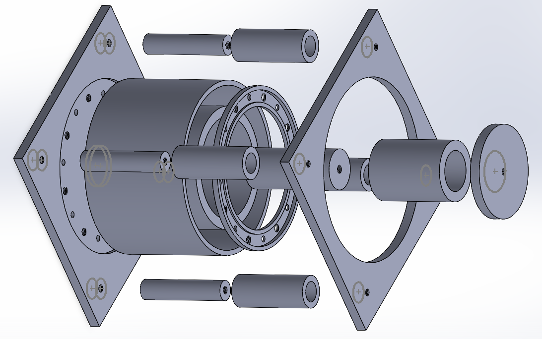
The 333000 CAD model is an attempt to make 331000 more realistic by adding holes and threads where necessary to allow standard M4 screws to fix and hold different components together along with appropriate insulation for certain components. There are minor changes in component dimensions to ease manufacturing, but the overall external dimension is still in milimeter length. It is an evolution of the 331000 and 332000 models, and will be elaborated further in later sections.
More realistic
More easily manufactured component-wise
M4 screws hold components together
Electrically charged anode insulated from entry shunt
Channel and entry shunt connection is not sealed (gas leakage)
¶ Narrowing the Design Options
¶ Requirements and Design Criteria
- Physical design requirements follow 2025_H_SE_PC_TS_THRUSTERS_P3.
- Mechanically adequate (components are held together appropriately and leakage is minimised).
- Electrically adequate (components which are meant to conduct electricity are well insulated from those that aren't).
¶ Trade-off Results
For manufacturing purposes, it is necessary to trade off simplicity for realism. For this sole reason, it is enough to investigate model 333000.
¶ Detailed Design
We now focus on 333000 and its previous iterations. The iterations are made to make the model more realistic in order for it to be manufactured. The screws and nuts to be used are standard M4 and are given in the links below.
- Screw ISO 4762 Bossard supplier ISO 4762 screw data sheet
- Nut ISO 4035 Bossard supplier ISO 4035 nut data sheet
¶ Iterations
The 331000 simulation model has been mentioned above. It follows the requirements of 2025_H_SE_PC_TS_THRUSTERS_P3 and is the basis upon which 332000 and 333000 models are improved. The dimensions and specifications are given in 331000_Specifications.pdf.
Good and simple for simulations
Not a realistic model
The 332000 iteration improves on the 331000 base model by adding holes and threads to allow standard M4 screws to connect different components together. There are also minor changes to individual component dimensions to ease manufacturing but the external dimension of in milimeter length remains unchanged. A detailed list of modifications of each component is given in 332000_Specifications.pdf.
Although the screws hold the model together, there are a few problems. By only using metallic screws and nuts, the model is not electrically adequate. This is seen in the entry shunt + channel + anode connection, fixed by 8 screws and nuts (screws pass from entry shunt through channel to anode and nut fixes it at anode). The anode should be connected to a power source as it must be charged in order to create a potential with the cathode. However, since the screw contacts the entry shunt, which is metallic, this would charge the entry shunt as well, which is undesired. Another problem is the model doesn't prevent leaks when injecting gas from the entry shunt to the channel as the entry shunt + channel connection is not sealed appropriately. Also, the amount of M4 screws in the entire model can be reduced and the lengths of the M4 screws connecting each component are not yet specified in the specifications document. Unnecessary threads in holes should also be removed. These problems are addressed in the third iteration 333000.
M4 screws hold components together
More easily manufactured component-wise
Amount of M4 screws can be reduced
Length of M4 screws not yet specified
Unnecessary threads in holes
Electrically charged anode not insulated from entry shunt
Channel and entry shunt connection is not sealed (gas leakage)
The 333000 iteration improves upon the 332000 version by reducing redundant M4 screws, removing unnecessary threads. The dimensions of the channel are modified to anticipate future changes in order to seal the 8 gas injection holes via 8 copper O-rings embedded at the bottom of the channel. Furthermore, the 8 screw entry holes in the entry shunt and channel have been modified to allow 8 insulating sleeve washers to pass through to insulate the electrically charged anode from the entry shunt. The holes are modified according to the dimensions of the following ceramic insulating sleeve washers. This has the advantage that each screw passing through the insulating sleeve and connecting the entry shunt + channel + anode can be used to conduct electricity from the power source to the anode, thereby charging a potential at the anode without the current escaping into the entry shunt.
A complete list of changes in dimensions and a list of required screw lengths to connect each component of 333000 is given in 333000_Specifications.pdf. Future modifications to the 333000 version needs to connect the diffuser system with the 8 gas injection holes at the entry shunt as well as seal off the entry shunt + channel connections with O-rings to prevent leakage.
M4 screws hold components together
More easily manufactured component-wise
Amount of M4 screws reduced
Length of M4 screws specified
Removed unnecessary threads in holes
Electrically charged anode insulated from entry shunt
Channel modified to anticipate changes (O-ring embeddings)
Diffuser system to be connected with entry shunt
Entry shunt and channel connection to be sealed with O-rings
¶ Test Reports
Since the HET channel is still at a CAD modelling stage and has not yet been manufactured, there are no test reports.
¶ Relevant Documents
- 2025_H_SE_PC_TS_THRUSTERS_P3 HET design requirements
- Screw ISO 4762 Bossard supplier ISO 4762 screw data sheet
- Nut ISO 4035 Bossard supplier ISO 4035 nut data sheet
- Ceramic insulating sleeve washer McMaster-Carr part no. 92107A116 data sheet
- Electric propulsion textbook for reference Fundamentals of Electric Propulsion: Ion and Hall Thrusters
- Fuel characteristics Xenon, Krypton, Argon fuels