¶ Thrust Control
¶ Introduction and motivation
Demo-A3 is the engine that will power the Icarus hooper. To land this aircraft, we need a Thrust Control system. This must be capable of modifying the oxidant and ethanol supply to the engine in real time to maintain the desired thrust intensity.
This system has already been theorized and tested in cold flow in 2022 as a semester project and will now be boosted to reach 100Hz and other features.
The system described on this page aims to push these tests further and thus create the code and solve the problems encountered during the first iteration. However, it should be noted that this board will not fly. On Icarus' hooper, this board will be merged with another.
¶ Requirements
| --- |
| Control architecture to maintain a desired thrust intensity |
| Control architecture to maintain OF ratio |
| Working rate = 100Hz |
| Reed 5 pressures sensors |
| Control 2 servos |
| Save data for now done on the raspberry |
| Receive data from Wago (% of thrust intensity) |
| Send data to back to TF |
¶ General System Operation
For our adaptive system to work, it must have :
- Two mass flow sensors based on the Venturi effect
- Two valves designed in-house and operated electronically
- A pressure sensor in the combustion chamber to calculate the thrust in real time (more explication about this equation in the software part)
- A microprocessor to read and operate everything
¶ User guide
 Thrust_control_user_guide
¶ Schematic
¶ Specifications
| --- | --- | --- |
| Component | Supplier | Reference |
| Controller | Raspberry | Raspberry PI 4 |
| Microprocessor | STMicroelectronics | STM32-F303-K8 |
| Board | EPFL Rocket team | HugoBoard v1.3 |
| Pressure sensors | Honeywell | MIPAG1XX050BSAAX |
| Servo | Savox | SB22290SG |
| Battery | Swaytronic | SWAY-TRX LiPo 2S 7.4V 4000mAh 45C/90C TRX |
¶ HugoBoard
The HugoBoard was designed by Hugo Jorand and Hugo Trombert as an interface board around the Nucleo F303K8. This board is chosen from the Nucleo, Arduino and Teensy boards as it has two ADCs, each with 8 channels, enabling more than 100Hz of sampling frequency, as required by Icarus. The previous board (designed by Alexandre Guerra) was based on a Raspberry Pi with external ADCs (the Raspberry Pi doesn’t take analog inputs), but the time for switching between channels led to an effective sampling frequency of only 30Hz on each pressure sensor. Theoretically, a Raspberry Pi with more ADCs could also have been used, although the Nucleo was deemed more adapted as it is used only for the thrust control task.
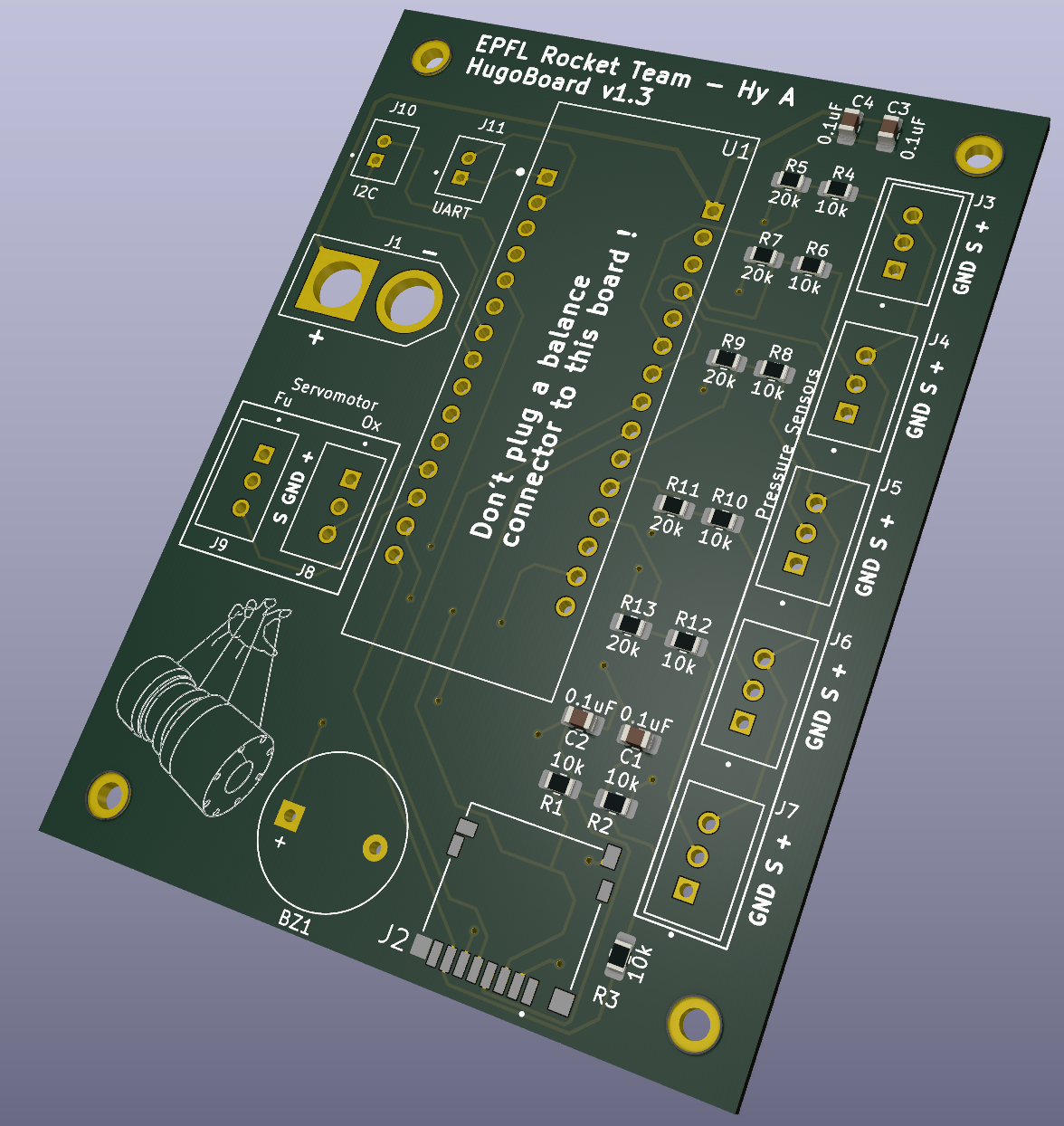
3D of the HugoBoard v1.3 design.
¶ Communication
The board is equiped with an UART (n°J11) and an I2C (n°J10) communication port. For now they are unused, as the communication with the Rasypberry is done with the USB (with UART protocol).
Communication with the SD is done with SPI.
¶ Power
The whole board is powered by a LiPo 2S battery, as the servos require an input voltage of 8.4V and the Nucleo needs between 7V and 12V. The battery capacity is 4000mAh, 45C/90C, giving a current well above the total peak current for the 2 servos, around 10A each. It is connected to the board with an XT60. The power input to the Nucleo board is stabilized by decoupling capacitors (100nF).
The pressure sensors are powered by the 5V from the Nucleo. As was done for the previous board, voltage dividers are used to scale down the analog output from the pressure sensors to 3.3V, as the analog inputs of the Nucleo boardare not 5V tolerant.
¶ Details
The servos and the pressure sensors are plugged with JST connectors to the dedicated pins on the Nucleo.
The Nucleo is plugged in the HugoBoard with header pins for ease of disassembly.
The built-in LEDs of the Nucleo are used for status, as well as an added buzzer on the board.
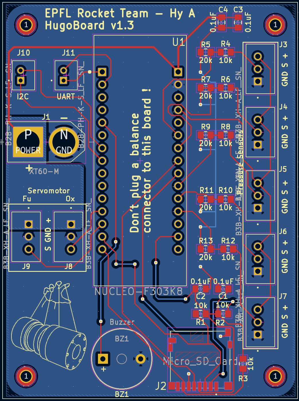
View of the PCB.
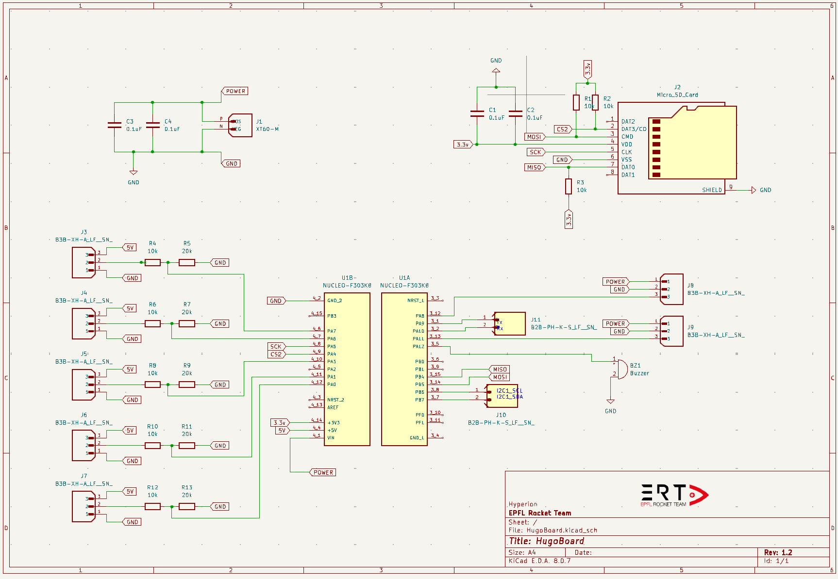
Schematic of the board
¶ Venturi
Our mass flow rate sensors are based on the Venturi effect. It's the fact that we mesure a reduction of pressure when a fluids goes in a constriction.
Mathematically, it's based on the Bernoulli's equation and the conservation of mass. After some modification we get to :
With : cross section area without constriction, : cross section of the constriction
¶ Software
¶ Architecture
Our software was developped in C in CubeIDE. For SD communication we use FatsFS.
Apart from main, there are 3 other header files that define mathematical, communications functions and variables.
This code run at more than 100Hz, and here are a block diagrams of the main parts.
Here are zoom on each parts :
¶ 1. Data saving
Data is saved in a .csv file with this format. For now, as the SD is hard to setup, this is saved on the raspberry.
| --- | --- | --- | --- | --- | --- | --- | --- | --- | --- | --- | --- | --- |
| Loop | Error | Angle Ox (°) | Angle Fu (°) | OF ratio | Real values: | Thrust (N) | Mass flow Ox (kg/s) | Mass flow Fu (kg/s) | Targeted values: | Targeted thrust (N) | Targeted Mass flow Ox (kg/s) | Targeted Mass flow Fu (kg/s) |
¶ 2. Testing Facility exchange
Testing Facility sends a thrust percentage and our board sends back : Pressure values, mass flow, Ox angle and Fu angle.
This can also be done without testing facility asking thrust values. You can also code certain values to be achieved in advance, and the Testing Facility wago will only send a GO and STOP to the board.
¶ 3. Pressure reading
Note that if pressure is equal to -10 it may be because no voltage is giving back from the sensor.
The Nucleo SM32f303 has 12 bits ADC so to get the voltage we need to do this transformation :
With : Vadc = Voltage supplied to the ADC (3.3 V), N = Number of ADC bits (12)
For reeding pressure we use Honeywell MIPAG1XX050BSAAX. they are working at 5V so we need to do a scaling to the ADC voltage :
From the datasheet here is the function we use to get the pressure from sensors :
¶ 4. Thrust calculation
This module has two main roles :
-
Transform venturies pressures in mass_flow_real and thrust_real (needed in data)
-
Transform requested thrust by Icarus (thrust %) in thrust_target (0-1000N), and in mass_flow_target (Ox and Fu)
Here are all equations :
At first here are the oxyder-fuel stoichiometric ratio :
With : mass flow oxidizer, : mass flow fuel
¶ Thrust Calculation
In order to know what's the current thrust magnitude, our system have a pressure sensor in the combustion chamber. With that inside the next formula, we can find out the exit pressure :
With : combustion chamber pressure, : specific heat capacity ratio, : Mach number, : exit pressure
So our current thrust magnitude with this known value , is :
With : out speed, : exit pressure, : atmospheric pressure, : cross section area at the exit of the nozzle.
¶ Mass flow Calculation
Icarus ask our system a thrust intensity, so we need to know what's the mass flow of fuel and oxidizer required. Let's note that the OF ratio must always be 3.5, so we have :
¶ 5. Control
¶ Schematic
Here is a schematic of the methodology : (Note A B C D the order of execution)
¶ PID Coefficients
For now, PID coefficients are unknown, as we need the valves characterization. But to determine it, we have a Simulink simulation who will help us.
From that we have to do a transformation from Simulink coefficient (parallel) to C code coefficient (series) :
TO BE VERIFIED
| --- | --- |
| PI in parallel and Simulink notations : | PI in series and C notations : |
| | |
It gave us :
¶ 6. Servo moving
We need a characterization of the valves to have the function: mass_flow_2_angle.
To make the servo running we have to generate a PWM signal. To do that we need to have a prescaler, a period and a duty cycle. Knowing this equation, we can deduce our prescaler and period values :
Please note the servo specifications :
- Frequency = 50 Hz
- Maximum travel = Appx 130° (800 to 2200 microsecond)
-> From tests we reach an angle maximum travel of 172°.
The greater the period is, the more precised we are. For a Nucleo frequency of 8Mhz, we need that :
Notice that it must be int. types who is smaller than 65535, so one of the best values for our applications is the next values (but maybe with presc = 3 and period = 53'333 it works, we have to test it)
Prescaler = 4
Period = 40000 [TIM1 ticks]
So now we have servo and TIM1 each at 50Hz, let's find the duty values (time in microseconds while the current is high). From specifications we have that for an angle range of 130°, we can change the duty from 900 → 2100 µs.
We have a period of 40'000 ticks mapped on a 20'000 µs (50Hz) so we just have to double the µs value (it's a linear relationship) :
Duty = [1800; 4200] -> angle = [0;130]°
¶ Meaning of error codes
| --- | --- | --- |
| N° | In architecture | N° | SD writing | N° | Servos | N° | ADC |
| 00 | No Error  | 10 | Error in Init_SD : f_mount error | 20 | PWM for J8 not started | 30 | Error in read_J3 : PollForConversion ADC_2_C4 |
| 01 | Error in time management : calculation time over 10ms | 11 | Error in Init_SD : f_getfree error | 21 | PWM for J9 not started | 31 | Error in read_J4 : PollForConversion ADC_2_C3 |
| 02 | TimeManagement Task is too long | 12 | Error in open_file : f_open error | 22 | / | 32 | Error in read_J5 : PollForConversion ADC_1_C4 |
| 03 | Control Task is too long | 13 | Error in Write_file : f_write error | 23 | / | 33 | Error in read_J6 : PollForConversion ADC_1_C2 |
| 04 | SD_writing Task is too long | 14 | / | 24 | / | 34 | Error in read_J7 : PollForConversion ADC_1_C1 |
| 05 | / | 15 | / | 25| / | 35 | No voltage from J3 |
| 06 | / | 16 | / | 26| / | 36 | No voltage from J4 |
| 07 | / | 17 | / | 27| / | 37 | No voltage from J5 |
| 08 | / | 18 | / | 28| / | 38 | No voltage from J6 |
| 09 | / | 19 | / | 29| / | 39 | No voltage from J7 |
¶ Data
 Github
 Drive
Drive¶ Assembly
Pressure sensors, servos and communications have matching connectors. Here they are :
| --- | --- | --- | --- | --- | --- |
| Connectors | Pressure sensors | Connectors | Matching servo | Connectors | Communications |
| J3 | Venturi Oxidizer In | J8 | Oxyder valve | J10 | I2C |
| J4 |Venturi Oxidizer Out | J9 | Fuel valve | J11 | UART |
| J5 | Venturi Fuel In |
| J6 | Venturi Fuel Out |
| J7 | Combustion Chamber |