¶ Introduction
This page is about rocket plumbing, detailing our considerations and the design process behind the fluid system of Firehorn.
To briefly describe the fluid system and its necessity in the rocket: the rocket engine requires fuel and oxidizer to utilize chemical potential and produce thrust. As combustion occurs at a specific pressure, the fluid system must deliver the required mass flows of both liquid oxygen and ethanol at the designated pressure.
To achieve this, the fuel and oxidizer tanks will be pressurized by an auxiliary system that utilizes high-pressure nitrogen.
¶ Definitions and Abbreviations
- DJF : Design Justification File
- LOX : Liquid Oxygen
- COPV : Carbon Overwrapped Pressure Vessel
- OD : Outer Diameter
- ID : Inner Diameter
¶ Relevant Knowledge Needed
The article will delve into the intricacies of fluid system design. Having a basic understanding of fluid dynamics would be advantageous. While the relevant equations are provided, the absence of sufficient context might make them somewhat challenging to comprehend.
Although not necessary here are some resources that are helpful for further understanding.
- Wikipedia: Darcy-Weisbach
- Wikipedia: Darcy friction factor
- Wikipedia: Flow coefficient
- Compressible Fluid Dynamics (FR)
¶ Design
¶ Plumbing Diameter choice
It was decided to utilize Swagelok tubing, and the following diameters were taken into consideration, with the respective nominal sizes (OD) in inches, internal diameters (ID) in millimeters, and pressure ratings in bars:
| Nominal Size (OD) [in] | Internal Diameter (ID) [mm] | Pressure rating [bar] |
|---|---|---|
| 1/4 | 3.9 | 510.3 |
| 1/4 | 4.9 | 272.2 |
| 3/8 | 6.2 | 442.3 |
| 3/8 | 7.0 | 326.6 |
| 1/2 | 8.5 | 455.9 |
| 1/2 | 10.9 | 176.9 |
| 3/4 | 16.4 | 163.3 |
| 1 | 22.1 | 163.3 |
Since Swagelok predominantly works with imperial dimensions, opting for imperial sizes as the outer diameter (OD) is more cost-effective and offers a broader selection.
¶ Wet Tubing
Wet tubing" refers to the plumbing components where fluids exist in liquid form during regular operation. In the present setup, only the main lines and the tubes responsible for loading ethanol and oxygen are designated as "wet."
In order to optimize both mass and cost, it is imperative to keep tubing diameters relatively small. Nevertheless, a critical consideration is that decreasing tubing diameter results in elevated flow speeds. This heightened speed, in turn, leads to increased viscous friction, causing a rise in pressure loss. It's crucial to balance the tubing diameter to avoid compromising performance optimization while still achieving the desired reductions in mass and cost.
Pressure drop in a fluid system can be calculated using the Darcy-Weisbach equation. The equation is commonly used to determine the head loss (pressure drop) in pipes and ducts due to fluid flow. The Darcy-Weisbach equation is expressed as follows:
Where:
- is the pressure drop
- the length of the tube
- the Darcy friction factor
- the density
- the mean velocity of the flow
- the hydraulic diameter
The friction factor can be determined through various approximations, leading to more precise estimations. In this case, the Moody diagram was utilized for a conservative estimation, resulting in . This is a rather conservative estimation but shall be sufficient for a rough estimation.
ID [mm] | [m/s] | | [bar] | [m/s] | | [bar]|
-|-|-|
7.0 | 29.1 | 1196.7 | 27.8 | 26.6 | 136.8 | 15.9|
8.5 | 20.0 | 992.5 | 10.9 | 18.3 | 113.5 | 6.2|
10.9 |12.1 | 770.9 | 3.1 | 11.0 | 88.1 | 1.8|
16.4 | 5.4 | 513.9 | 0.4 | 4.9 | 58.8 | 0.2|
For LOX the third diameter seems like a reasonable choice although pressure drop is rather high with this compromises the cost of having to select bigger valves as the next tube has an OD of 3/4 in. The Oxygen main line is rather short as the LOX tank is right above the engine so the total pressure drop will not be that big.
For Ethanol the same diameter is selected using a similar argumentation. Even though relative pressure drop is at the main line is much longer than the LOX counterpart so it will lead to comparable or bigger total pressure drop.
¶ Dry Tubing
Under dry tubing, the focus is on tubes where the fluid is typically in its gaseous form. This applies to both the pressurization system and the venting systems.
Here, the density is much lower than in wet tubing; therefore, the pressure drop is generally lower. This allows for a smaller tubing diameter. What needs to be considered, compared to wet tubing, is the possibility of choked flow.
Assuming compressible isentropic flow in order to have a coked flow () the following equation has to be fulfilled:
Where:
- is the pressure at the nozzle
- is the pressure in the tank
- is the heat capacity ratio
In this case it ideal gas is assumed and = 1.4 due to diatomic Nitrogen there is cocked flow. Obviously, this is the case as pressure in the COPV and nominal tank pressure so the pressure ratio is where the second is the pressure ratio necessary for chocked flow for diatomic gas.
For isentropic flow the massflow through a nozzle can be calculated using the folowwing formula:
As we want the mass flow of the system defined by the Electronic Pressure Regulator (EPR) the chocked flow shall occur in the valve not in the tubing. Following the tubing has to be selected such that the crosssection is bigger than for the mass flow of Nitrogen required to pressurize the tank. It shall be noted that this shall be true for the entire burn duration. Obviously the pressure of the COPV, and the Temperature in the COPV are changing during the burn phase, so this shall not be neglected.
Taking this in account we know the volume flow rate that is leaving the tank so we can determine the mass flow rate necessary to replace that volume with a ideal gas at a given pressure.
By replacing the mass flow in the above expression and solving for we find that the diameter of the Tubing has to be bigger than 5.8 mm therefore a diameter of 3/8 would be needed. An argument can be made that no matter the tubing diameter as long as the smallest diameter is not the tubing sonic conditions will occur there first and therefore tubing diameter does not impact mass flow. As the smallest orifice is in the pressurisation valve it was selected to opt for 1/4 in tubing for the testing setup for the pressure regulator and increase diameter if tests are non-satisfactory.
¶ COPV size
A simplified model of the pressurisation was programmed. The model consists of a COPV, two Tanks and the combustion chamber. For simplicity a constant combustion chamber pressure was supposed and between tanks and combustion chamber a simple discharge coefficient was introduced.
Between the COPV and the Tanks isentropic flow through a small orifice and sonic conditions in the orifice is assumed. The following graph depicts the evolution of the pressure in the Tanks. Initially the main valves are closed and there is no flow between combustion chamber and tanks.
The graph below shows the pressure in a Propellant tank. It shall be noted that the burn time is about 33 seconds instead of 15 seconds for operation with nominal mass flow.
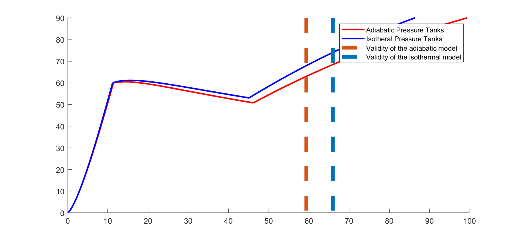
Playing with COPV sizes let to determine a absolute minimum of 5L are necessary. Due to the accuracy of this simulation and a 6L COPV was selected.
¶ Valves
Cylindrical or spherical valve stems are necessary for limited flow control, as a stable ignition can be achieved using only a small fraction of the nominal mass flow. The valve must possess capabilities for flow control. A V-port valve appears ideal for this application due to a linear relationship between the opening angle and the flow coefficient. V-angles below 30 degrees were not considered due to a significant reduction in the total cross-section. In this case, V-ports of 60 degrees and 90 degrees were considered.
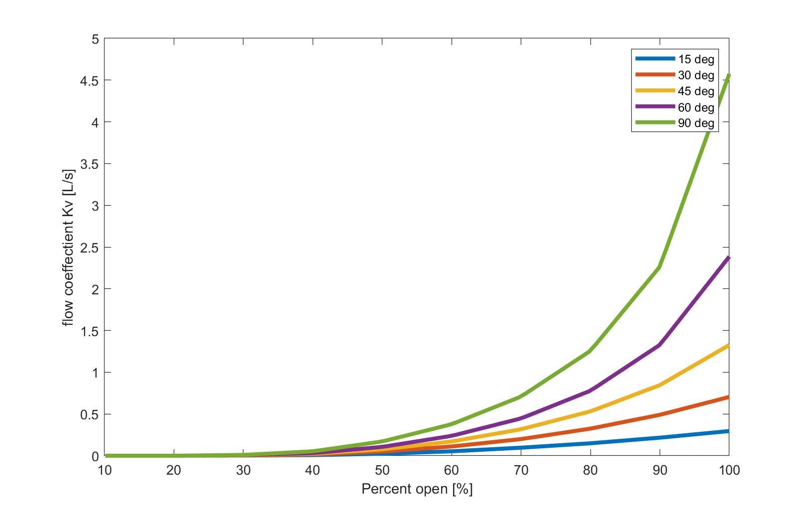
It was decided to use a 90-degree port and order a 60-degree replacement ball. If the flow coefficient of the 90-degree port at low flow rates is unsatisfactory, it can be easily replaced.
¶ Fluid Diagramm
¶ Tubing Arrangement
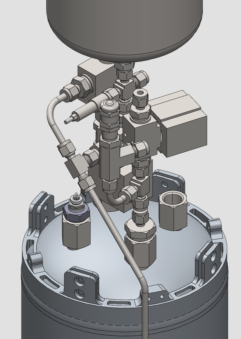
To fulfil the length requirements a spatial arrangement has to be found to make the system as compact as possible. A good method for this task is to have a rough idea of the valve dimensions. Sketch a possible arrangement by hand, then go to CAD to verify if said arrangement is possible and respects integration diameters.
¶ Pressurant Bay
As shown in the fluid diagram the Pressurant Bay contains:
- COPV
- Electronic Pressure Regulator
- Ethanol Vent
- Pressure Sensor 400bar
- Check valve
- Pressure Sensor 60bar
- Fill level Sensor
- Burst disk or Relief device for the ethanol tank
In the following Figure an example was made of a possible configuration of the Pressurant Bay wiht the COPV on top and ethanol tank on the bottom.
The high pressure Nitrogen system will decend on the outside of the rocket. There will be a aerocover protecting the tube and the cables that are routed around the ethanol tank.
¶ Mid Bay
As shown in the fluid diagram the Pressurant Bay contains:
- Electronic Pressure Regulator
- LOX Vent
- Check valve
- Pressure Sensor 60bar
- Fill level Sensor
- Burst disk and Relief device for the LOX tank
The
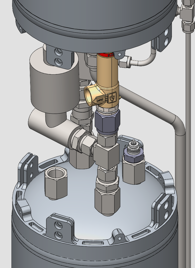
The ethanol main line passes on the outside of the rocket similarly to the Nitrogen line. The Venitng system on the LOX tank is more capable than the ethanol vent system to prevento overpressure due to evaporation and for simplified filling of the LOX tank.
¶ Design Iterations
As this is the inital design until now no deficit in the above described design was discovered as no testing of the system occured. Iterations will follow.