¶ Introduction
The document is the Design Justification File for sensor package of the Test Bench Assembly. The goal of the test bench is to measure the thrust of electric propulsion system in vaccum chambers. The sensors used to fulfill those goals are torque sensors provided by Kistler (model 9329A and 9339A).
¶ Definitions and Abbreviations
- DJF : Design Justification File
- EPFL: École Polytechnique Fédérale de Lausanne
- TVC : Thermal Vacuum Chamber
- PPT: Pulsed Plasma Thruster
¶ Applicable and Reference Documents
The sensors are part of the test bench assembly and the general interface with the TVC
The Test bench is the combination of the mechanical design with two sensors and an electrical interface with the vaccuum chamber.
-
Data sheet Data sheet for the sensors provided
¶ Relevant Knowledge Needed
The conversion to get the thrust from the torque measurement is done by knowing the distance between the torque sensor and the thrust application and dividing the moment measured by this distance.
The DJF for the whole assembly shows where the torque sensor is being used in the assembly.
¶ Detailed Design
Kistler's engineers recommended the sensors to us based on our need (thrust of thruster, vacuum compatibility, etc...). There was no iteration on sensor choice and more so on sensor integration. The sensors recommended do not have the same dimensions. The integration of the sensor is recommended by the sensor's data sheet. The iteration is based on the fedback for Kistler's engineers.
¶ Iterations
This version accomodate one type of sensor at a time. The sensor is flush into both the holder and the attachement in the lever arm. THe first picture shows the sensor in place and the second picture show the hole for the sensor to fit in.
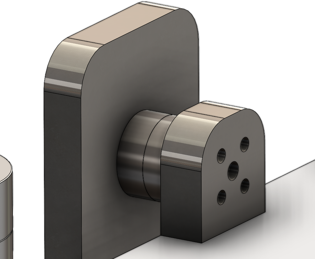
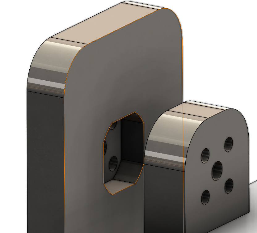
Less load on the sensor
Accomodates only one sensor at a time
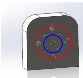
This version can accomodate both sensors using screws instead of a flushing the sensor into a fitted hole. The red circle on the first picture shows the holes to use for the big sensor (9339A) while the blue circle shows the dimensions for the small sensor (9329A).
Accomodates both sensors (more modular)
Bigger load on the sensors and the screws.
¶ Relevant Documents
- Data sheet Data sheet for the sensors provided