¶ Introduction
The objective of the Design Definition File (DDF) is to establish the technical definition of a system or product that complies with its technical requirements specification.
The Filling Station is a crucial part of the Ground Support Equipment (GSE), responsible for managing oxidizer transfer to the Launch Vehicle (LV) in a safe and efficient manner.
This document outlines the structural, thermal, plumbing, and electrical components of the filling station, including the technical specifications and operational constraints.
¶ Definitions and Abbreviations
- GSE : Ground Support Equipment
- LV : Launch Vehicle
- NC : Normally Closed
- NO : Normally Open
- PCB : Printed Circuit Board
- DC : Direct Current
- N₂O : Nitrous Oxide
- FCT : Functional Test
- PHY : Physical Constraint
- OP : Operational Requirement
¶ Applicable and Reference Documents
- EPFL Rocket Team Documentation on GSE Operations (WIKI)
- Industry Standards for Cryogenic and High-Pressure Fluid Handling
- NASA Cryogenic Fueling Guidelines
- ASTM Standards for High-Pressure Valves
¶ Requirements
- The filling station shall support oxidizer transfer at a controlled flow rate of 5 L/min.
- The system shall allow for remote operation up to 500 meters away.
- The station must have emergency shut-off capabilities within 1 second.
- The system shall be able to withstand a maximum pressure of 70 bar.
- The station shall be modular for easy transportation and assembly.
¶ Interfaces
- Mechanical Interface : The oxidizer bottle mounting system and LV connection.
- Electrical Interface : Power supply of 15V DC, 24V DC and 36V DC, and telemetry communication.
- Data Interface : Wireless telemetry link for status monitoring and remote operation.
¶ Overview
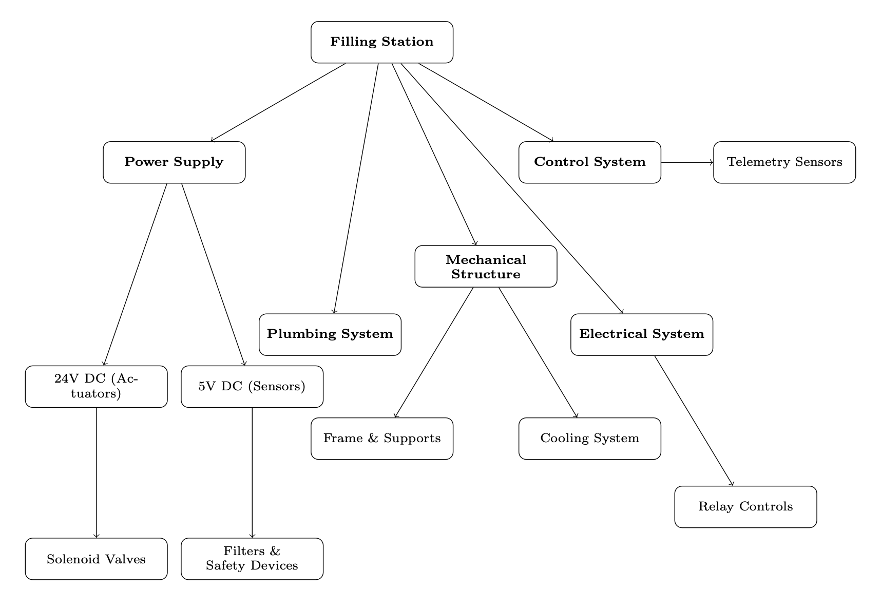
The filling station is designed as a modular unit, integrating:
- A lightweight but sturdy aluminum frame to support heavy loads.
- A thermally controlled oxidizer storage system.
- A high-pressure plumbing network with safety redundancies.
- A remote-controlled electrical actuation and monitoring system.
¶ Parts Description
¶ Mechanical Components
The mechanical structure of the filling station consists of an aluminum alloy frame designed for strength and portability. The frame is constructed from modular aluminum profiles connected via brackets, allowing for easy assembly and disassembly. The oxidizer bottle is mounted on a set of secure brackets with vibration-dampening supports to minimize mechanical stresses during transportation and operation. A wheel system is integrated at the base, enabling smooth transport over uneven terrain. The frame also includes attachment points for securing additional components such as the control electronics and chiller unit.
¶ Plumbing System
The plumbing system comprises stainless steel tubing, high-pressure-rated solenoid valves, and pressure relief components. The primary oxidizer flow path is managed by two solenoid valves: a normally closed (NC) fill valve and a normally open (NO) purge valve. The system also incorporates a Swagelok filter with a 7-micron mesh to prevent debris from entering sensitive components. The plumbing layout is optimized for minimal pressure drop and thermal insulation to reduce heat transfer from the environment.
AJOUTER GRAPHE PLUMBING GSE

¶ Electrical System
The electrical system includes a custom-designed PCB, a sensor array, and
a telemetry module for remote monitoring. The main control board, Super-
TOAST Mk.I, is responsible for processing sensor data and executing commands from the remote ground station. The PCB integrates an 8-channel relay board that interfaces with the solenoid valves and actuators. Power is supplied via 3 different inputs of 15V DC, 24V DC and 36V DC input. The inout of 15V DC is regulated down to 9V for specific components. A set
of thermocouples and pressure transducers provide real-time status feedback, allowing operators to monitor the oxidizer flow rate, pressure levels, and system temperature.
AJOUTER GRAPHE BOX GSE
¶ Power Supply and Voltages
The filling station generates multiple voltage levels for different subsystems:
| Voltage Level | Purpose |
|---|---|
| 36V DC | Dedicated supply for avionics power when interfacing with the LV. |
| 24V DC | Primary power source, used for solenoid valves, relays, and high-power actuators. |
| 15V DC | Dedicated supply for avionics power when interfacing with the LV. |
| 5V DC | Power supply for sensors, microcontrollers, and communication devices. |
| 3.3V DC | Used for logic-level signals and low-power microelectronics. |
¶ Control System - SuperTOAST Mk.I
The control unit of the filling station is the SuperTOAST Mk.I PCB, which
is responsible for:
- Reading sensor data (pressure transducers, thermocouples, flow meters).
- Controlling actuators such as solenoid valves, pistons and relays.
- Determining the filling status of the tanks
- Managing telemetry communication with the ground station.
¶ Interfaces
- 8 Analog Inputs: For precise sensor readings.
- 8 Digital I/O: Configurable for controlling external devices.
- Dual LoRa Radios: For full-duplex wireless communication.
- Ethernet and CAN Bus: For local and vehicle communication.
- Battery Backup System: Ensures operation during power failures.
¶ Technical Budget, Margins, and Deviation
When updating the Filling Station, we determined necessary to upgrade the flow rate of NO2. In order to do that, we ordered a solenoid valve with a better coefficient
than the one used in the original design. This will allow us to fill faster the tank.
¶ Design Constraints
¶ Constraints for Production
The manufacturing process of the GSE structure presents several constraints that must be considered to ensure feasibility and efficiency. Material selection plays a crucial role, as aluminum profiles and sheets require precise cutting, de-burring, and surface finishing to maintain uniformity and prevent injuries during
assembly. The Wheel Support Beams and Axle modifications introduce constraints related to machining accuracy,requiring access to a Drill Press, Lathe,
and tapping tools to achieve the necessary thread dimensions. The Plumbing Plate and Electronics Box modifications demand careful manual drilling
and sanding, emphasizing the need for precision to maintain proper alignment and fitment. Furthermore, the Chiller Plate, initially manufactured from MDF via laser cutting, presents a structural limitation, which could be improved by switching to aluminum or reinforced steel for increased rigidity. These constraints necessitate the use of specialized tools and an optimized workflow to ensure efficient and high-quality production.
¶ Constraints for Operation
The filling station must function in outdoor conditions with temperatures ranging from -10°C to 50°C. The control system must be operable from a remote ground station.
¶ Other Constraints
The design should be lightweight yet robust, meeting safety standards while ensuring easy transportability.
¶ Conclusion
The filling station is designed to facilitate safe and efficient oxidizer transfer. It integrates structural, electrical, plumbing, and safety features, ensuring reliability during launch operations.