¶ Introduction
This document outlines the recent (Fall 2024) structural changes to the drone and describes the detailed design and dimensions. The drone is a testing platform for the Guidance, Navigation, and Control (GNC) team’s algorithms. Please note that the design of the gimbal will not be covered in this document, for more details click here.
¶ Structural Breakdown
Loosely speaking, the structure can be subdivided into 4 segments.
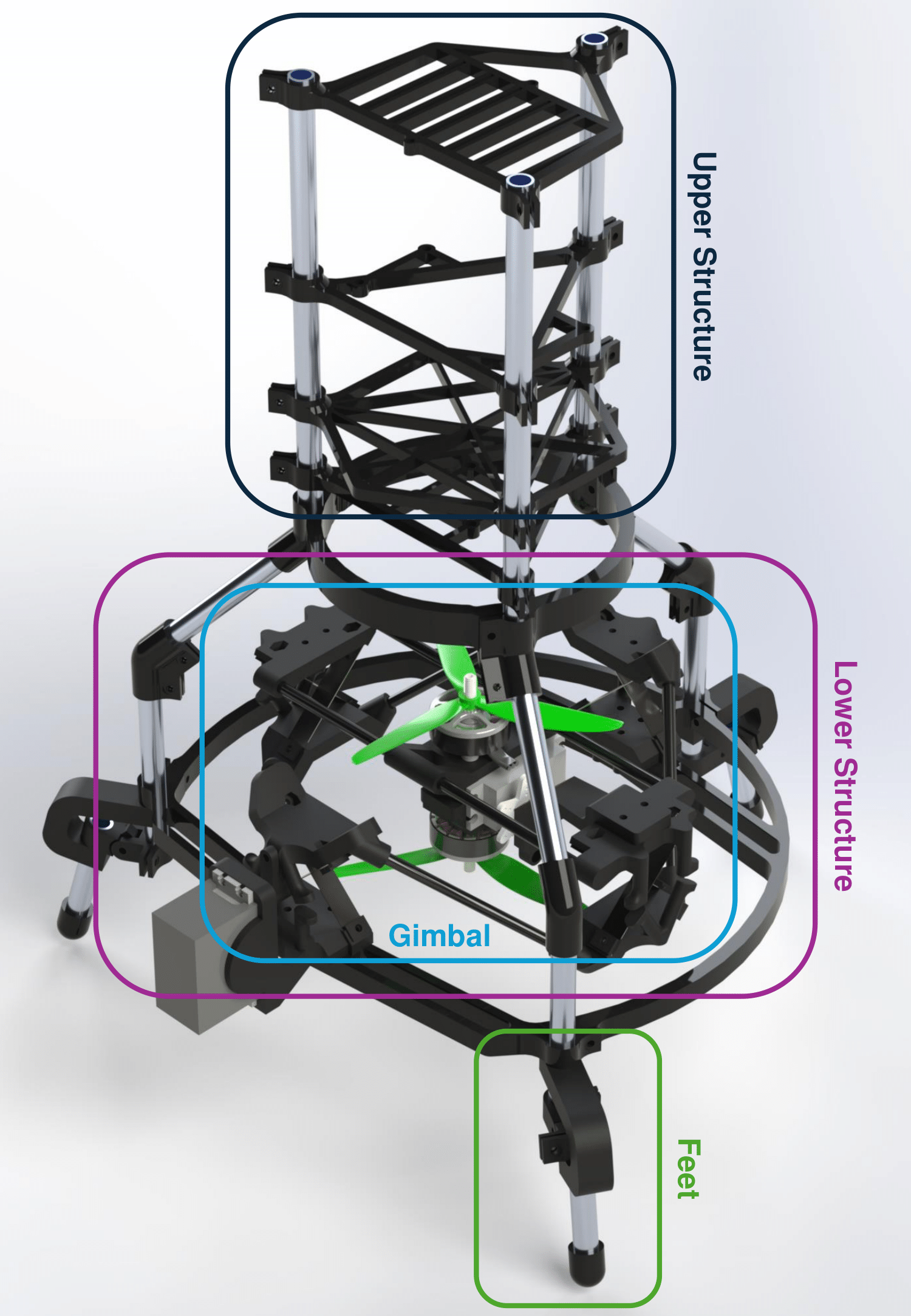
- Upper structure: Houses the shelves for various electronics.
- Lower structure: Supports the Gimbal and connects the feet and the upper structure
- Feet: Dampen impact from potential crash landings
- Gimbal: Vectors the thrust of the motors
¶ Technical Specifications
¶ Feet
¶ End-Cap
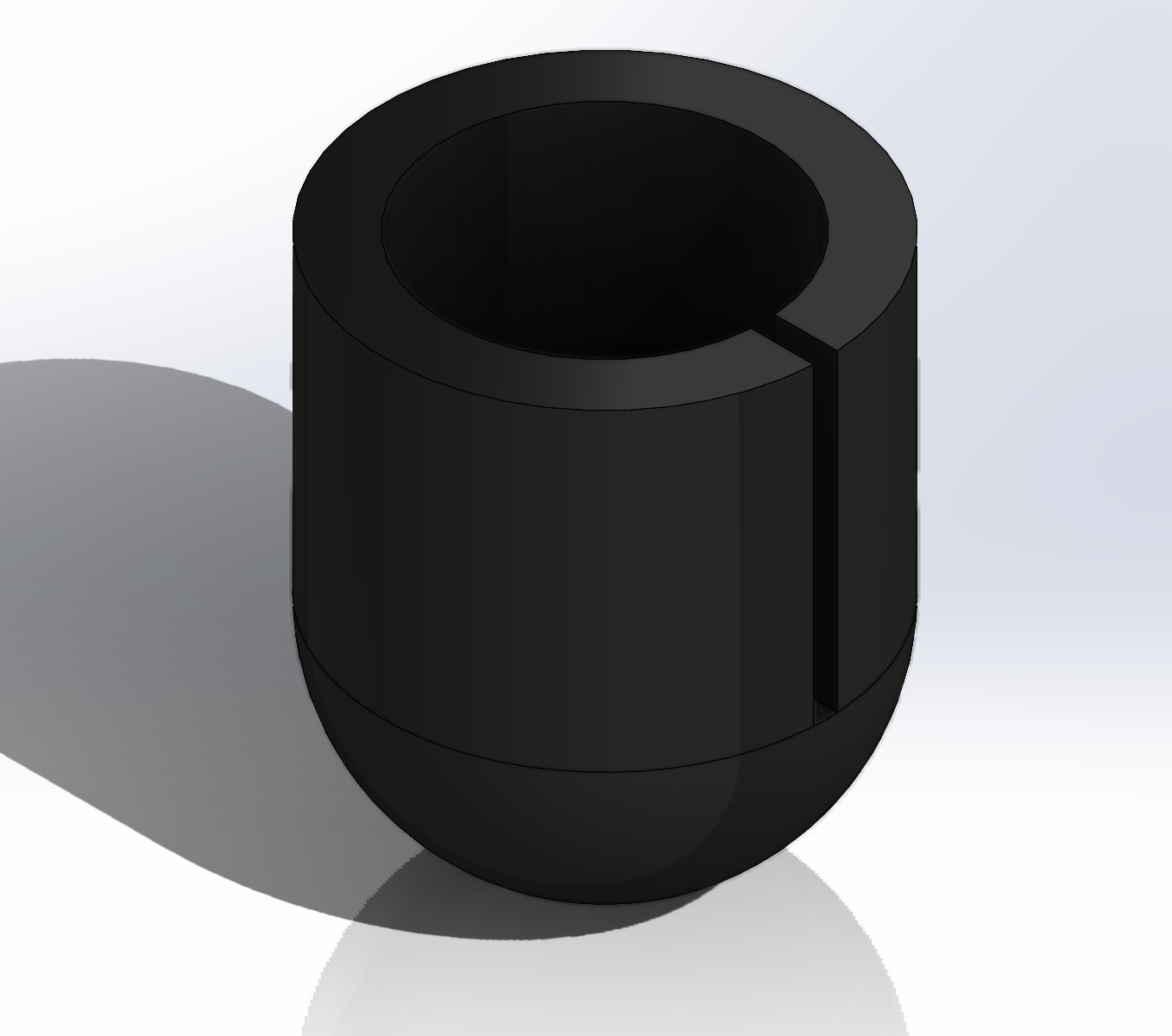
Easy and quick printing foot. It prevents snagging onto the ground. A slit was added to help the cap bend a bit during assembly. Additionally, the inside was chosen to be conical with an angle of 45° to improve printability.
- Material: PETG
- Perimeters: 6
¶ TPU Spring
Compliant piece that acts like a spring and damper in one. It is prestressed to 10°, i.e. the neutral position of the TPU is 10° further than the one of the hinge.
- Material: Ninjaflex TPU
- Perimeters: 4
- Infill: Grid, 15%
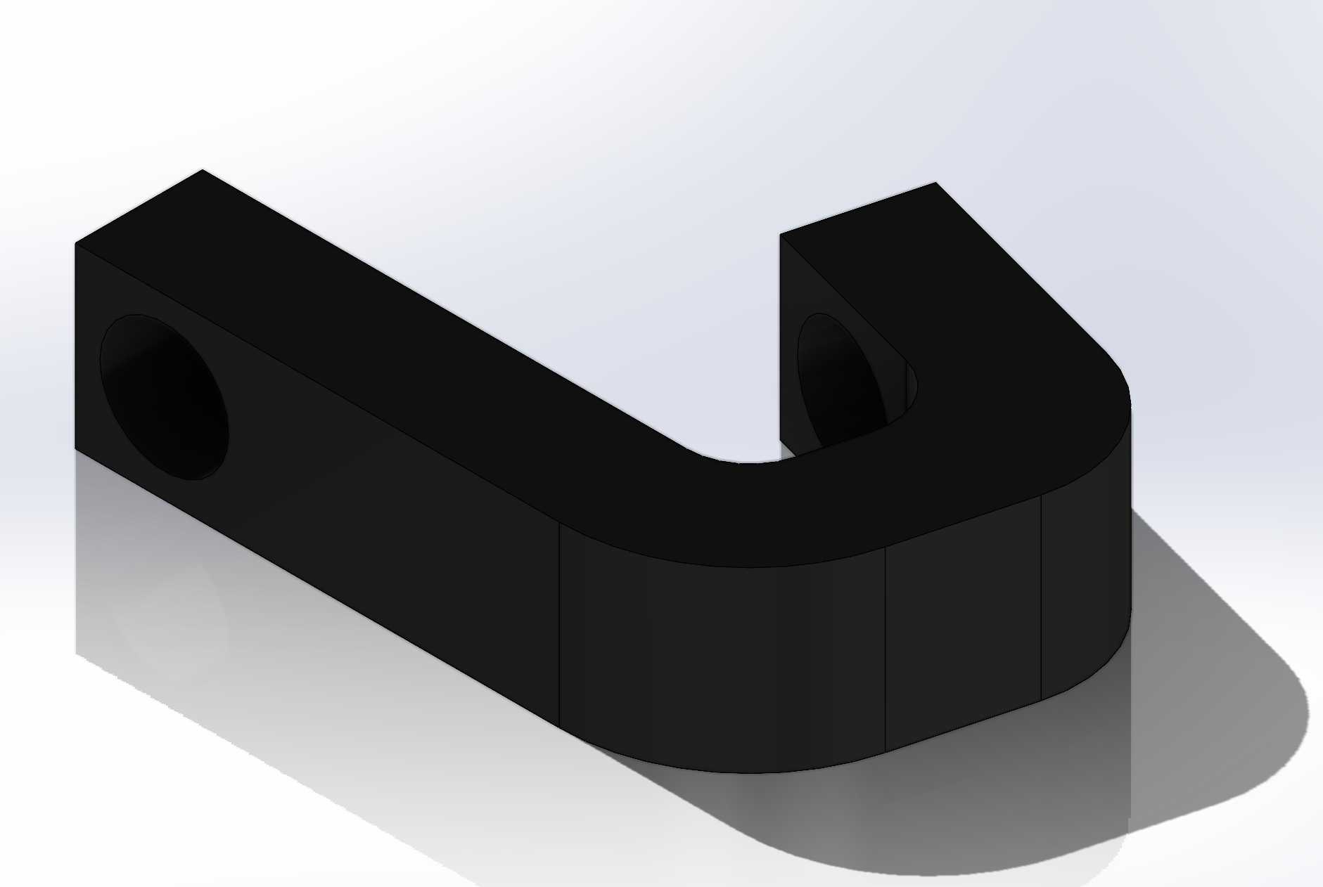
¶ Hinge
As mentioned above the hinge is constructed such that the TPU piece is prestressed by 10°. The hinge pin is simply a M3 screw, secured using a Lock nut to prevent the screw from squishing and therefore blocking the hinge. Note that for better visibility the material has been removed.
- Material: PETG
- Perimeters: 6
¶ Lower Structure
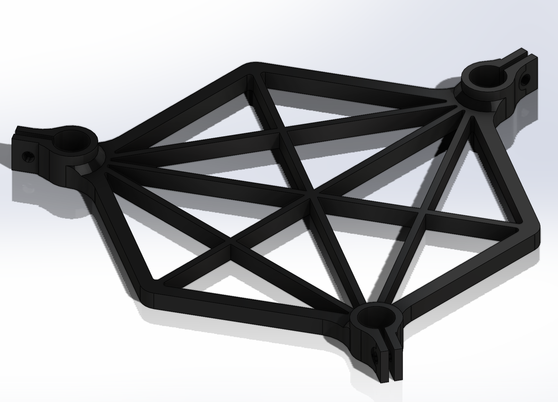
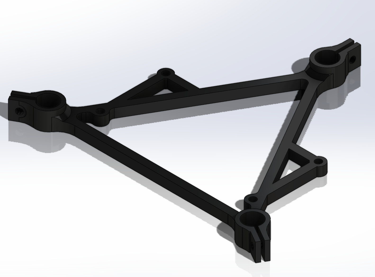
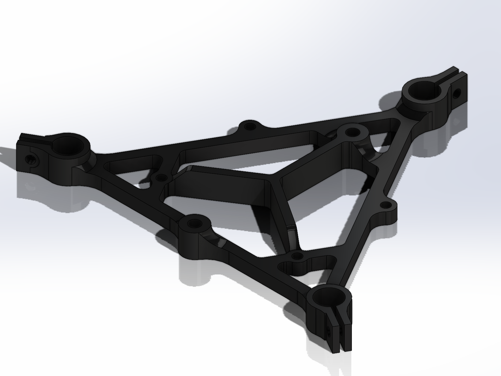
¶ Bottom Ring
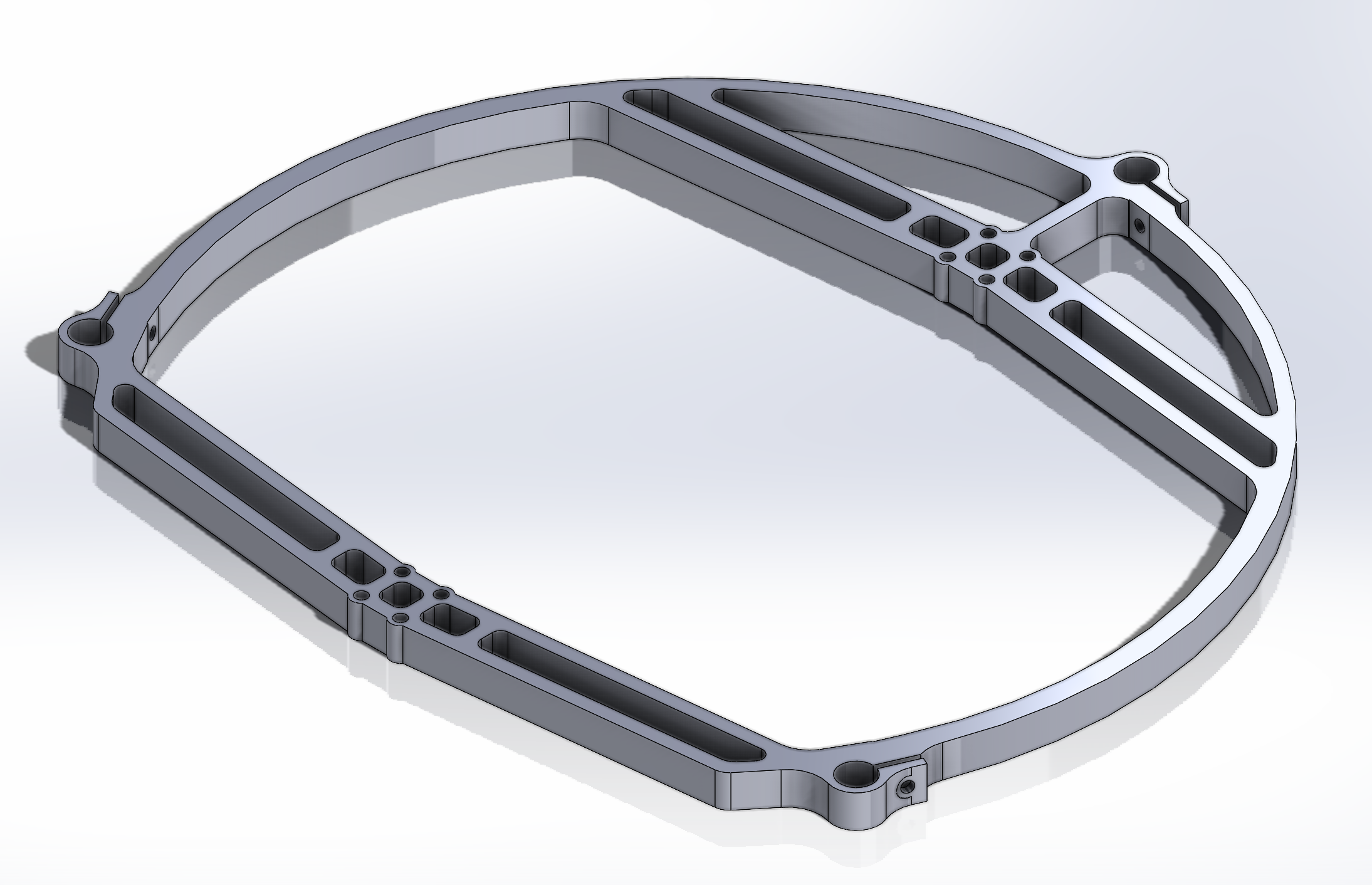
The bottom ring supports the gimbal, and connects to the feet. For added rigidity, as it was a problem with V3R2, the width of the arcs connecting both sides was increased to 6. Additionally, more trusses were added to help reduce the weight.
- Material: PETG
- Perimeters: 6
- Printer: Prusa XL
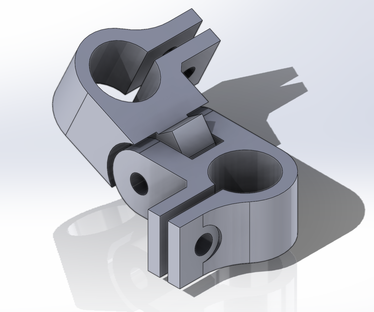
¶ Elbow Joint
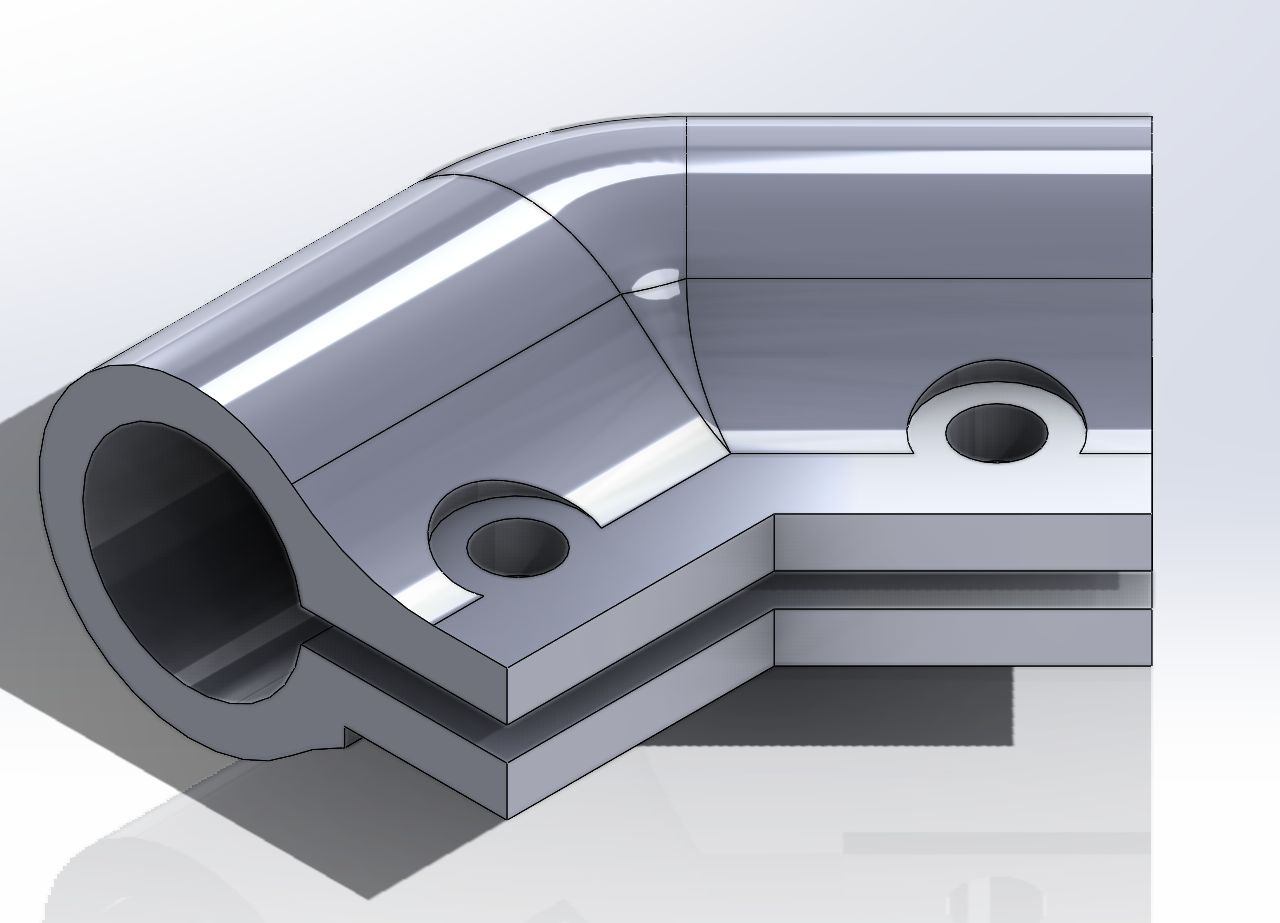
The elbow joint, although small, contributes a lot to the final rigidity of the assembly. The two flaps have been connected for better printability and rigidity, as the first moment of area is increased.
- Material: PETG
- Perimeters: 6
¶ Connection Ring Upper-Lower Structure
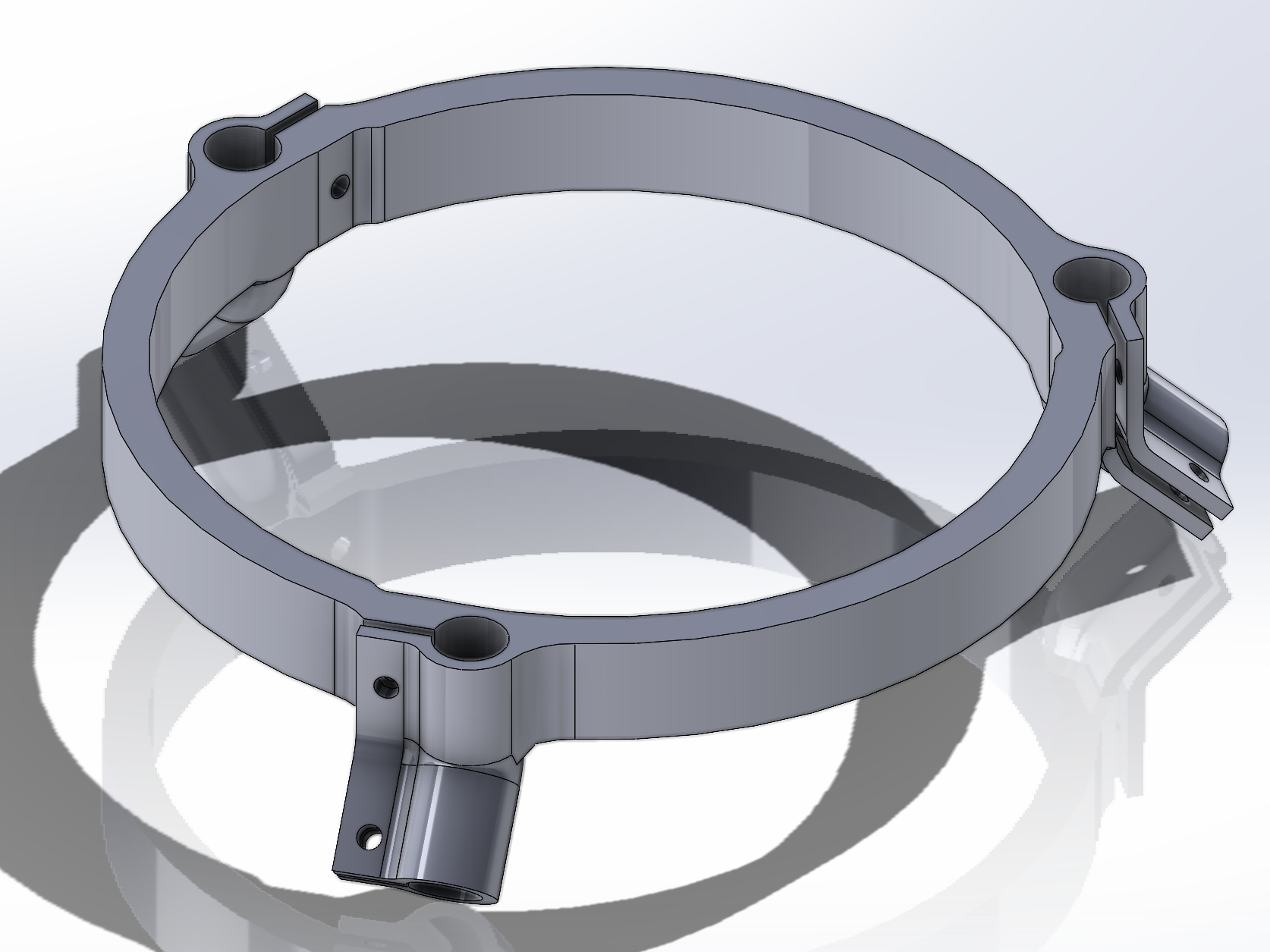
The connection ring must be rigid and strong to link the upper and lower structures. It too makes use of the clamping mechanism. Since the rods sit at a 45° angle, it is perfectly possible to print in one piece.
- Material: PETG
- Perimeters: 6
Drawing (for clamp dimensions please refer to the hinge drawing)
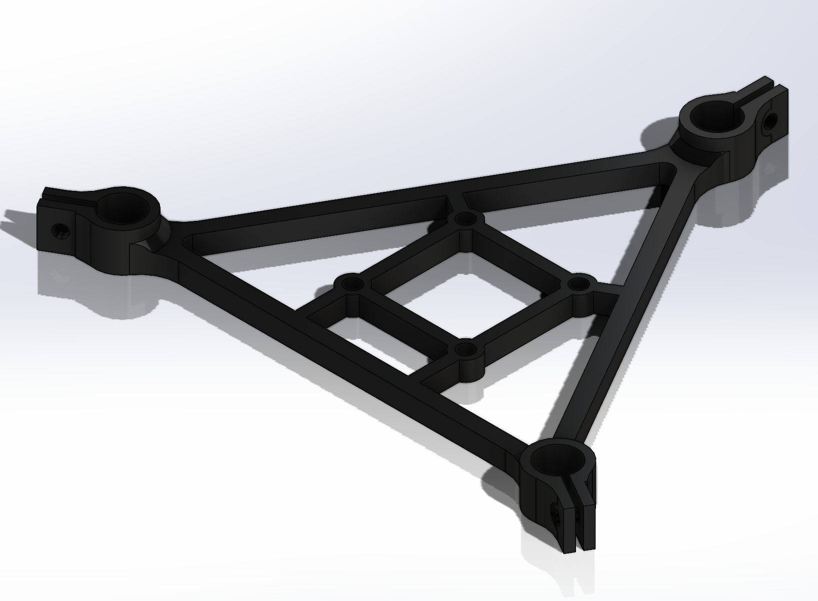
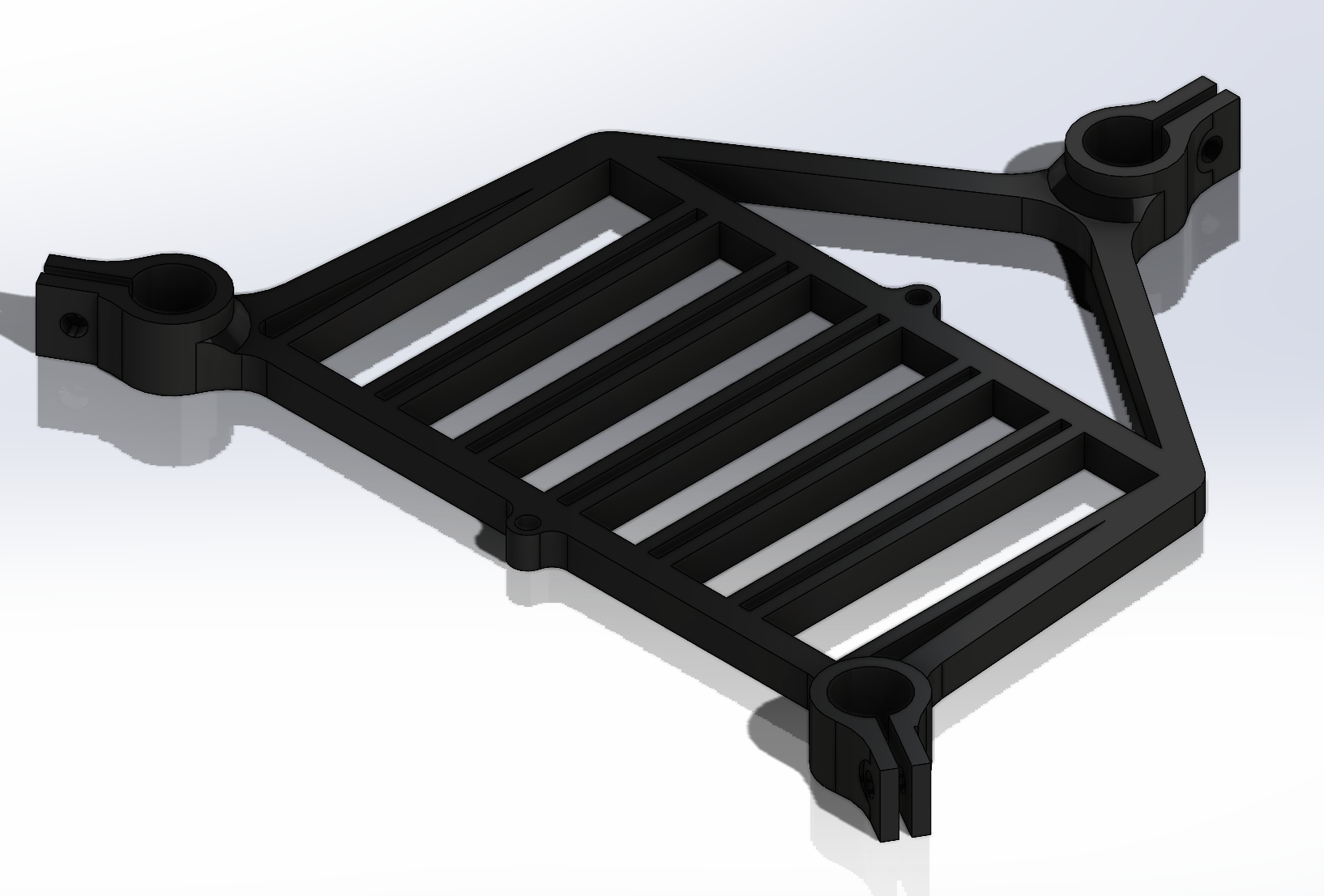
¶ Upper Structure
All mounts are based on the same base design. The clamps are 10 tall, and the structural parts of the mount measure 5x4.
¶ ESC Mount
- Material: PETG
- Perimeters: 6
¶ Battery Mount
- Material: PETG
- Perimeters: 6
¶ Avionics Mount
- Material: PETG
- Perimeters: 6
¶ Auxiliary Board Stablizier Mount
- Material: PETG
- Perimeters: 6
¶ GPS Mount
- Material: PETG
- Perimeters: 6