¶ title: 2023_ST_TN_D02_Internal_Coupling
description: Link: https://rocket-team.epfl.ch/en/rocket_ss/structure/Nordend/2023_ST_TN_D02
published: true
date: 2025-05-21T19:11:28.678Z
tags:
editor: markdown
dateCreated: 2023-07-11T06:36:45.493Z
¶ title: 2023_ST_TN_D02_Internal_Coupling
description: Link: https://rocket-team.epfl.ch/en/rocket_ss/structure/Nordend/2023_ST_TN_D02
published: true
date: 2024-12-30T21:17:56.344Z
tags:
editor: markdown
dateCreated: 2023-07-11T06:36:45.493Z
¶ title: 2023_ST_TN_D02_Internal_Coupling
description: Link: https://rocket-team.epfl.ch/en/rocket_ss/structure/Nordend/2023_ST_TN_D02
published: true
date: 2023-12-01T02:42:11.165Z
tags:
editor: markdown
dateCreated: 2023-07-11T06:36:45.493Z
¶ Internal Coupling Technical Note
¶ 1. Introduction
The internal coupling system allow us to attach the nosecone and the recovery module to the main structure. This system also provides a separation point for access to the payload. Refer to the Nosecone TN for exact location.
¶ 2. Reference Documents
| Ref | Description | Doc. ID | Issue |
|---|---|---|---|
| [G01] | Internal coupling simulations | Link to the report | 2023 |
¶ 3. Definitions and Abbreviations
| --- | --- |
| FoS | Factor of safety |
| FEM | Finite element method |
| ST | Structure |
| ERT | EPFL Rocket Team |
| EPFL | École Polytechnique Fédérale de Lausanne |
| TD | Technical drawing |
| ATPR | Atelier de l’Institut de production et robotique
¶ 4. Design
¶ 4.1. Requirements
Engineering requirements :
- Design of a coupler to attach the nosecone to the rest of the structure
- Need to be an attachment point for the RE module
- Two M8 holes is the interface between the RE module and the internal coupling
- Internal part have to be bonded with the injection bonding method
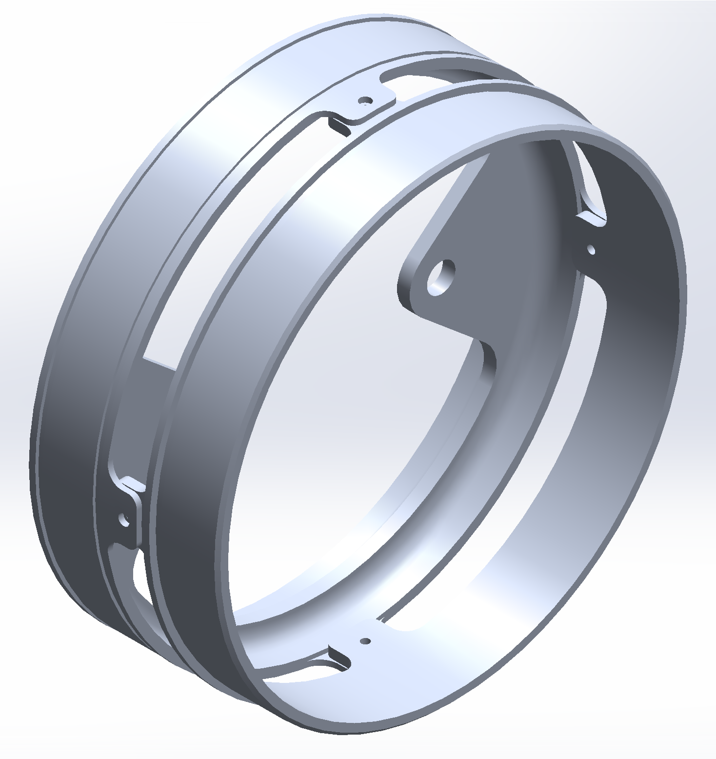
¶ 4.2. Design Overview
The main system consists of two aluminium machined parts. The internal coupler is bonded into the crfp tube with the injection bonding method. The nosecone coupler is bonded to the end of the slide-in of the nosecone. The two parts are attached together with 4 m3 screws, which allow the nosecone to be fixed to the rest of the rocket structure, but also act as a separation point for access to the payload. The internal coupler serves also as an attachment point to the RE module with two M8 holes.
This design has already been used on the Bella Lui II rocket and was tested in real conditions during its nominal flight. However, this design has great potential for improvement, because even though it's a system that has worked on previous flights, it has a few flaws that make it less than optimal. Firstly, the method of attachment between the two parts is not optimal because in this configuration the screws work mainly in shear. Secondly, the system remains two machined aluminium parts, which is rather expensive.
¶ 4.2.1. Design Specifications
| --- | --- |
| Height | 58 [mm] |
| Diameter | 152.8 [mm] |
| Weight | 0.252 [kg] |
| Material | Al 6082 T6 |
¶ 4.2.2. Annotated Renders
¶ 5. Simulations (optional)
¶ 5.1. FEM Simulations
¶ FEMs inputs summary :
| Software | Simulation Type | FoS | Material | Material Yield Stress [MPa] | Poisson's ratio | Simulation Force [N] |
|---|---|---|---|---|---|---|
| Abaqus | Static - isotropic | 1.5 | Al 6082 T6 | 260 | 0.33 | 3000 |
The simulations were carried out as part of a project for the finite element modelling and simulation course at EPFL. The study focused on the internal coupler and the nosecone coupler. The report details the entire simulation methodology and can be found on the report [G01]. The study includes a static analysis, a modal analysis and a thermal analysis for cryogenic temperatures.
¶ 5.3. Final results and comments
With an FoS of 1.5 applied to the force exerted in our simulation, it's important to note that the maximum stress reached on the part is 261.83 MPa. While this value is slightly higher than the elastic limit of aluminum, it is within the acceptable range for our design. However, it's essential to acknowledge that simulations inherently carry some degree of uncertainty, and real-world conditions may vary. Nevertheless, our design has been validated within the specified safety margin, ensuring its structural integrity under normal operating conditions.
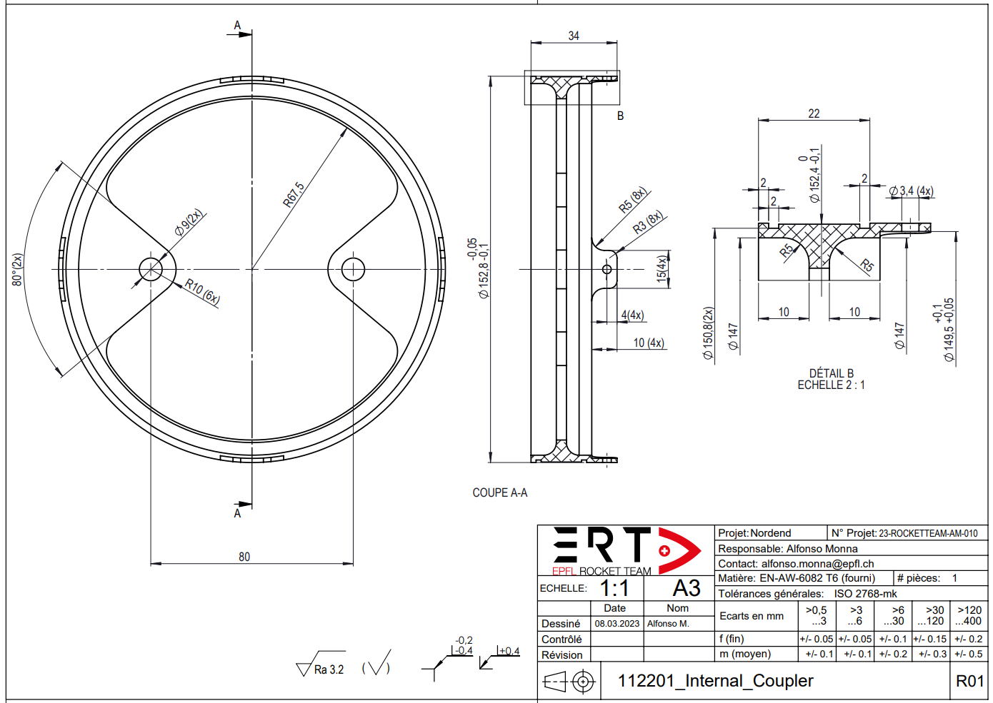
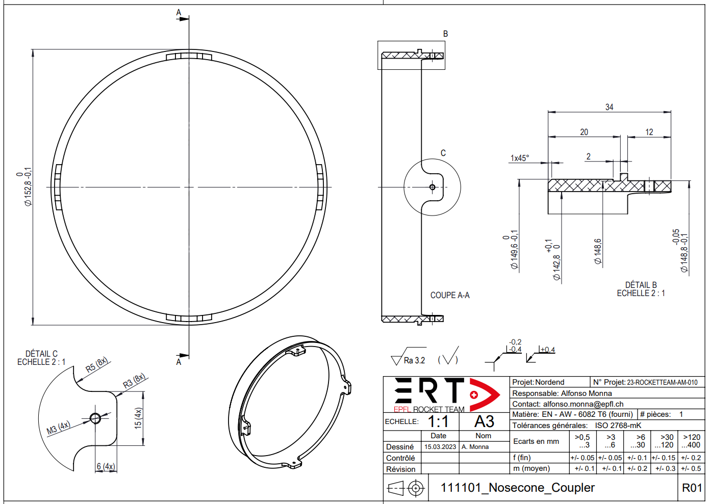
¶ 6. Technical Drawings
The parts were sent to the ATPR workshop. Once the parts have been machined, we can see that the tolerances set on the TDs are sufficient for the parts to function properly.
The technical drawings are also available in pdfs under the following drive folder.
¶ 7. Conclusion
In summary, the internal coupling system consists of two aluminum machined parts: the internal coupler and the nosecone coupler. They ensure the good attachment of the nosecone and the RE module to the main rocket structure.
While this design has been used successfully before, it has room for improvement due to non optimal attachment methods and the use of CNC machined components. Structural analysis shows that the design maintains safety margins. Overall, our design is validated for normal operations, but future iterations can explore improvements in attachment methods for enhanced efficiency and cost reduction.