¶ title: 2023_ST_TN_G03_End_Ring
description: Link: https://rocket-team.epfl.ch/en/rocket_ss/structure/Nordend/2023_ST_TN_G03
published: true
date: 2025-05-21T19:13:03.341Z
tags:
editor: markdown
dateCreated: 2023-08-23T15:04:50.144Z
¶ title: 2023_ST_TN_G03_End_Ring
description: Link: https://rocket-team.epfl.ch/en/rocket_ss/structure/Nordend/2023_ST_TN_G03
published: true
date: 2024-12-30T21:18:21.172Z
tags:
editor: markdown
dateCreated: 2023-08-23T15:04:50.144Z
¶ title: 2023_ST_TN_G03_End_Ring
description: Link: https://rocket-team.epfl.ch/en/rocket_ss/structure/Nordend/2023_ST_TN_G03
published: true
date: 2023-12-01T02:43:50.948Z
tags:
editor: markdown
dateCreated: 2023-08-23T15:04:50.144Z
¶ End Ring Technical Note
¶ 1. Introduction
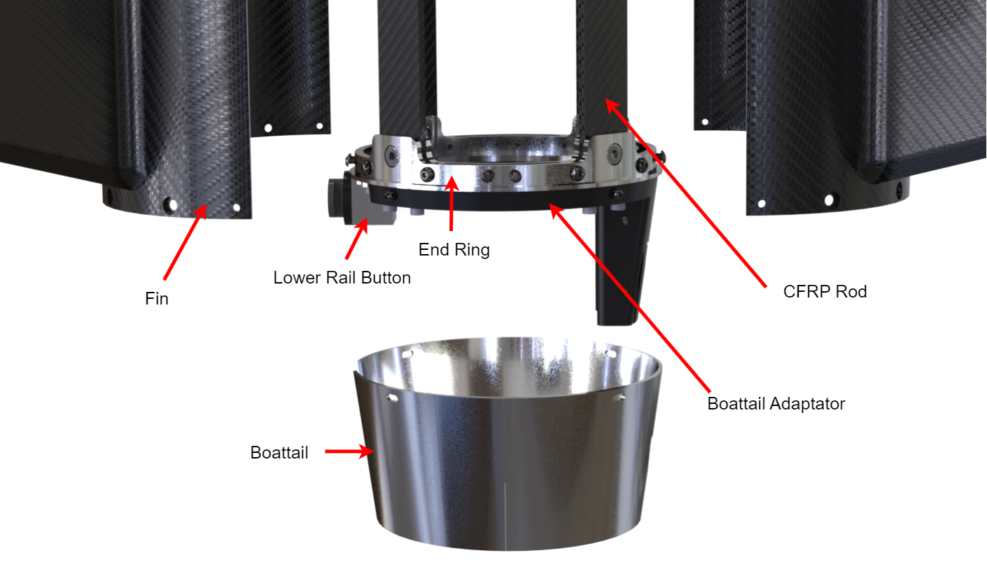
The End Ring is the ring located at the bottom of the rocket just above the Boattail. The role of the End Ring is to be an attachment point for the CFRP Rods, the Boattail adaptator, the lower rail button and the fins.
¶ 2. Reference Documents
| Ref | Description | Doc. ID | Issue |
|---|---|---|---|
| [G01] | Rail Buttons | 2022_ST_TN_G01_RAIL_BUTTONS | 2022 |
| [G02] | Fly away rail buttons | 2022_ST_TN_G02_FARB_Design | 2022 |
¶ 3. Definitions and Abbreviations
| --- | --- |
| CFRP| Carbon Fiber Reinforced Polymer |
| FoS | Factor of safety |
| FEM | Finite element method |
| ST | Structure |
| ERT | EPFL Rocket Team |
| EPFL | École Polytechnique Fédérale de Lausanne |
¶ 4. Design
¶ 4.1. Requirements
Engineering requirements :
- Provides anchoring for the 4 CFRP Rods of the EIS
- "Single hole" clamping "ears"
- 4 “ears” for rods interface
- 8 M4 holes and 8 M3 for fins interface
- Oblong holes for Retractable Rail Button placement with an angle tolerance of at least 5 degrees.
¶ 4.2. Design Methodology
The end ring was subjected to many modifications during it's lifecycle, it is subjected to many interfaces, namely the engine, the internal structure of the EIS, the fins and the boattail assembly.
At the early stages of conception it managed directly these interfaces with a centering geometry for the engine, double holes ears, attachement points for the boattail and a cutout for the cable of the igniter port of the engine.
A preliminary version of the End Ring
However it was found that this design was too complicated to manufacture, thus it was simplified, the boattail, engine and igniter port interfaces points were moved to a 3D printed boattail adaptator part.
Please note a couple remarks :
- The oblong holes for the RRB serves as a way to mitigate the misalignement of the modules due to the threaded coupling solution used on Nordend. A 5 degrees offset beetween the top RRB (attached on the Control Module) and the lower RRB (attached on the End Ring) can be mitigated this way.
- The fin lip serves as a reference point for the fins installation when bolted to the EIS. Without it there is a risk of mis-installation of the fins leading to an inclined fin, inducing an unstable flight.
- In the early stages of conception the fins' anchoring was assured by only 4x M3s per fin, two of them threaded inside the End Ring. It was however found to be insufficient rigidity wise. Thus 4x M4s were added to the fins, close to their root, 2 of them threaded inside the End Ring.
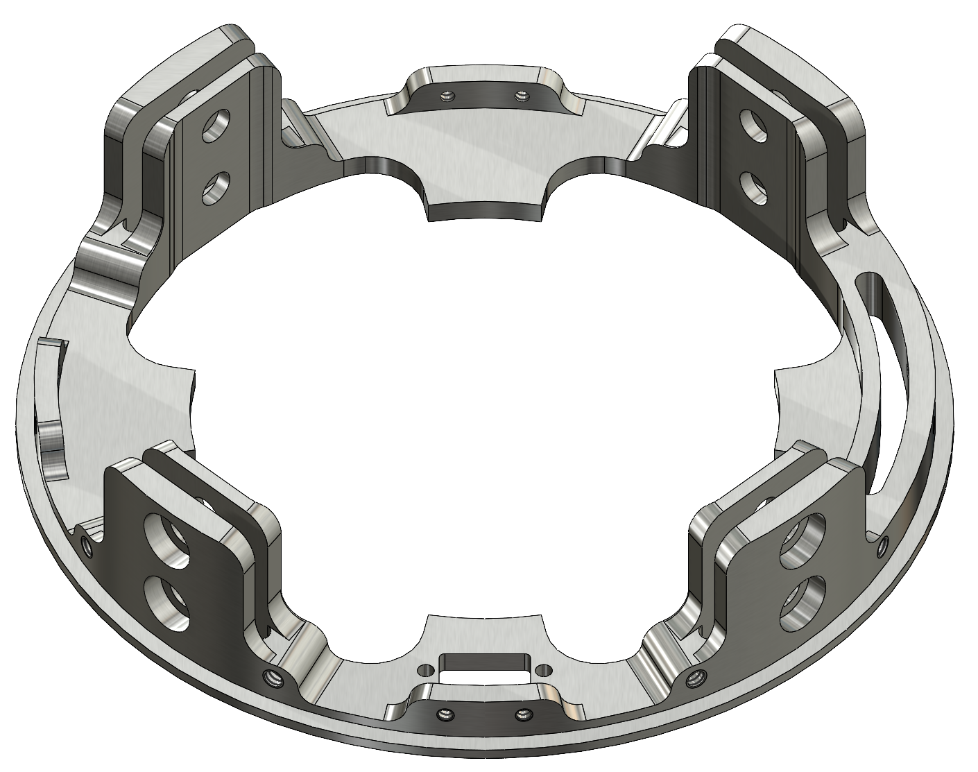
- To reduce part complexity, weight & the dimensions of raw materials, and due to low loads on the parts the end ring "ears" were switched to a one hole design instead of two (used in the rest of the internal structures).
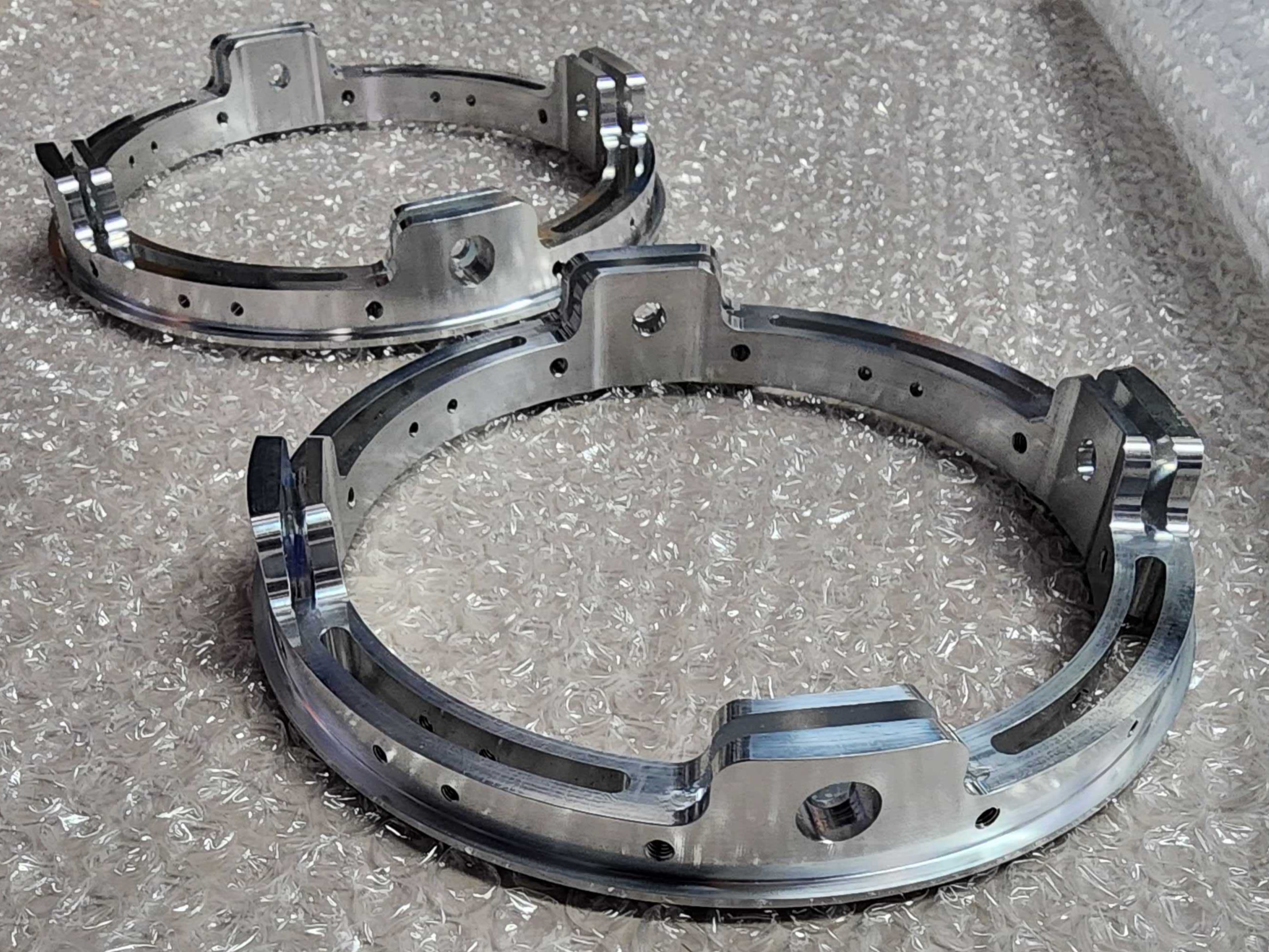
¶ 4.3. Design Overview
¶ 4.3.1. Design Specifications
| --- | --- |
| Height | 24.5 [mm] |
| External Diameter | 159 [mm] |
| Internal Diameter | 128.8 [mm] |
| Weight | 0.162 [kg] |
| Material | Al 6082 T6 |
¶ 4.3.2. Annotated Renders
¶ 5. Simulations
As the end ring is not subjected to high loads, only preliminary simulations were run on the part, indicating very low stress. As such no final simulations were run on it.
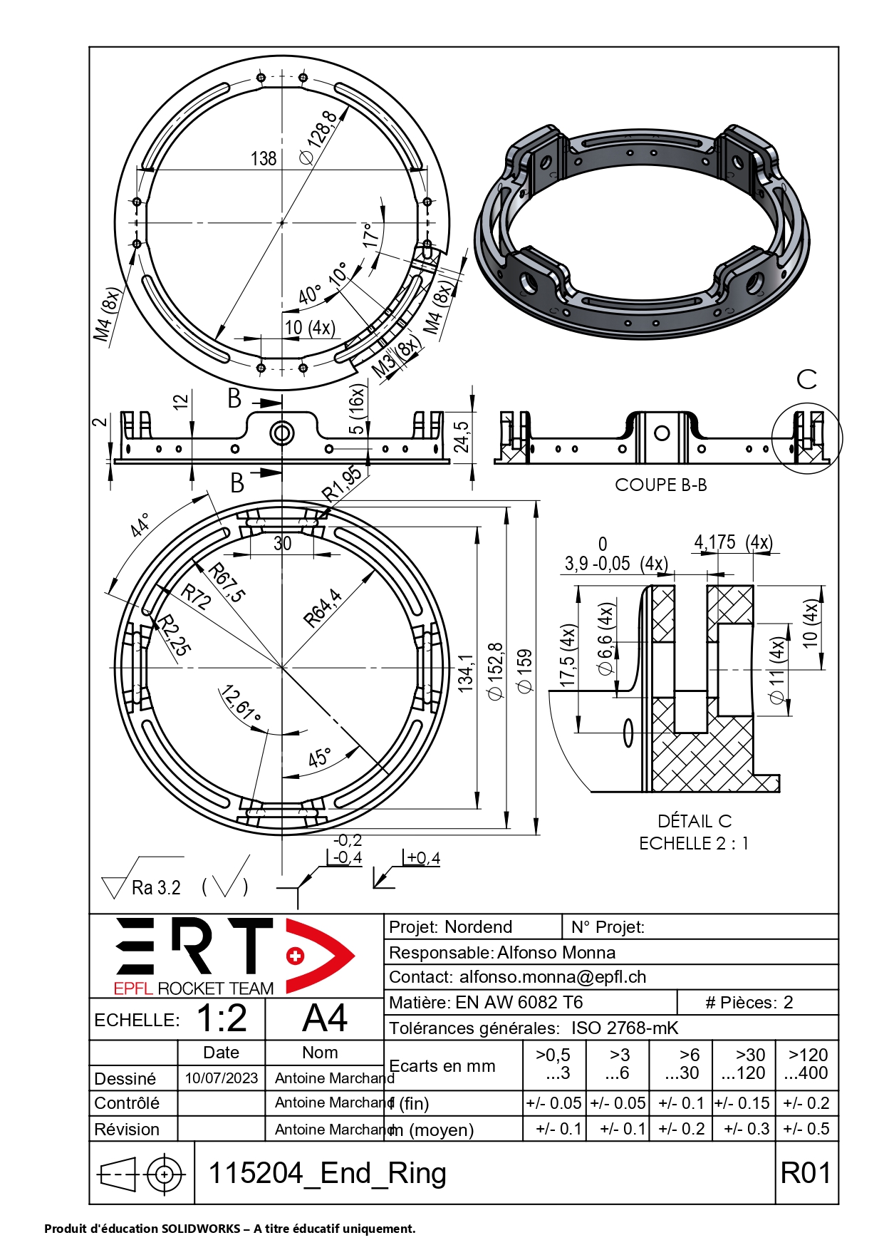
¶ 6. Technical Drawings
The End Ring was sent to ATME workshop, so it does not have any Production Procedure.
This part is machined using a conventional 3 axis milling machine.