¶ Introduction
¶ Purpose, Objective and Scope
The objective of this Design Definition File (DDF) is to go over the computations done on the last version of the Hopper Structure to make sure it complies with the requirements of the vehicle. It will not go into the design choices of each sub assemblies. This is done in summary in the DJF (Design Justification File) of the main structure or in detail in the DJF of the specific sub assemblies. All of these files can be found here.
¶ Definitions and Abbreviations
- ST : Structure
- AV : Avionics
- PR : Propulsion
- LV : Launch Vehicle
- DOF : Degree of Freedom
- CDR : Critical Design Review
- BOM : Bill of Material
¶ Applicable and Reference Documents
- Design Requirement List (2024 DRL)
- High-Level Interface Management (2024 HLIM)
- Bill of Material and production plan of the Hopper (2024 BOM)
- Critical Design Review (CDR) of the Hopper on the 13.05.2024
- Flexure-based gimbal with high support stiffness for rocket thrust vector control (IAC2023)
- Compliant mechanism Simon Henein's thesis
¶ Requirements
Here are the requirements that apply to the design of the structural parts. The rest of the requirements can be found here.
-
2024_I_REQ_7
Total Dry Mass
The LV's total dry mass shall be [69'0000][±2'000]g. -
2024_I_REQ_9
Total Height
The LV's total height shall be [2'300][±200]mm. -
2024_I_REQ_11
Desert environment
The LV should satisfy the IP54 water and dust ingress standard (IP STD). -
2024_I_REQ_12
Temperature Range
The LV shall operate within the temperature range from [-10]°C to [50]°C. -
2024_I_REQ_14
Radial acceleration
The LV and all its components shall withstand [3.5]g of radial acceleration. -
2024_I_REQ_15
Axial acceleraion
The LV and all its components shall withstand [10]g of axial acceleration. -
2024_I_ST_REQ_1
Declaration of Purpose
The ST shall guarantee the structural integrity of the LV. -
2024_I_ST_REQ_2
Subsystems assembly
The ST shall guarantee that every LV's subsystem can be integrated to ensure the functionning of the LV. -
2024_I_ST_REQ_3
Assembly human needs
The assembly of the ST shall require at most [4] operators. -
2024_I_ST_REQ_4
Symmetry
Excluding propulsion elements, the ST shall be quadri-symmetric.
-
2024_I_ST_AVIONICS_BAY_REQ_1
Declaration of Purpose
The Avionics bay shall hold all the boards and antennas of the AV subsystem. -
2024_I_ST_AVIONICS_BAY_REQ_2
Avionics Bay - Avionics Interface
The AV Bay shall host the bards of the AV subsystem. -
2024_I_ST_AVIONICS_BAY_REQ_3
Avionics Bay - Upper Structure Interface
The AV Bay shall be directly mounted on top of the upper structure. -
2024_I_ST_AVIONICS_BAY_REQ_4
Avionics Bay Length Contribution
The AV Bay's length shall be at most [400]mm. -
2024_I_ST_AVIONICS_BAY_REQ_5 Avionics Bay Mass Contribution
The AV Bay's mass shall be at most [2'400]g. -
2024_I_ST_AVIONICS_BAY_REQ_6
Avionics Bay RF Considerations
The AV bay shall be designed to minimize RF interferences. -
2024_I_ST_AVIONICS_BAY_REQ_7
Avionics Bay Accessiblity
The AV Bay shall be designed so as to maximize the antennas's clearence. -
2024_I_ST_AVIONICS_BAY_REQ_8
Avionics Bay Axial Mass Distribution
The AV Bay's center of mass shall be no further that [10]mm from the LV's central axis.
-
2024_I_ST_UPPER_STRUCTURE_REQ_1
Declaration of Purpose
The Upper Structure shall host the propellant tanks. -
2024_I_ST_UPPER_STRUCTURE_REQ_2
Upper Structure Structural Elements
The Upper Structure's flight and pressure loads shall be born by the propellant tanks. -
2024_I_ST_UPPER_STRUCTURE_REQ_3
Upper Structure - Propulsion Interface
The Upper Structure shall host the Propulsion's "pressurization circuit" plumbing. -
2024_I_ST_UPPER_STRUCTURE_REQ_4
Upper Structure - Middle Structure Interface
The Upper Structure shall be mounted onto the middle structure. -
2024_I_ST_UPPER_STRUCTURE_REQ_5
Upper Structure Length Contribution
The Upper Structure's length shall be at most [760]mm. -
2024_I_ST_UPPER_STRUCTURE_REQ_6
Upper Structure Mass Contribution
Excluding propulsive elements, the Upper Structure's mass shall not exceed [6'200]g. -
2024_I_ST_UPPER_STRUCTURE_REQ_7
Upper Structure Axial Mass Distribution
The Upper Structure's center of mass shall be no further that [10]mm from the LV's central axis. -
2024_I_ST_UPPER_STRUCTURE_REQ_8
Upper Structure Accessiblity
The Upper Structure shall be mounted so as to be within arm's reach of any operator. -
2024_I_ST_UPPER_STRUCTURE_TANKS_REQ_1
Declaration of Purpose
The upper structure's tank shall be used as the on-board storage of propellant. -
2024_I_ST_UPPER_STRUCTURE_TANKS_REQ_2
Tanks Nominal Pressure
The propellant tank shall maintain a nominal pressure of [40][± 2]bar. -
2024_I_ST_UPPER_STRUCTURE_TANKS_REQ_3
Tanks Propellant Load
The tanks shall contain propellants for at [15]s-long mission.
-
2024_I_ST_MIDDLE_STRUCTURE_REQ_1
Middle Structure - Avionics Interface
The batteries shall be mounted onto the Middle Structure. -
2024_I_ST_MIDDLE_STRUCTURE_REQ_2
Middle Structure - FTS Interface The FTS shall be mounted onto the Middle Structure. -
2024_I_ST_MIDDLE_STRUCTURE_REQ_3
Middle Structure - Propulsion Interface
The COPV shall be mounted onto the Middle Structure. -
2024_I_ST_MIDDLE_STRUCTURE_REQ_4
Middle Structure - Propulsion Interface
The propulsion's "engine circuit" shall be mounted into the Middle Structure. -
2024_I_ST_MIDDLE_STRUCTURE_REQ_5
Middle Structure - Legs Interface
The legs shall be mounted on the Middle Structure. -
2024_I_ST_MIDDLE_STRUCTURE_REQ_6
Middle Structure Length Contribution
The Middle Structure's length shall be at most [680]mm. -
2024_I_ST_MIDDLE_STRUCTURE_REQ_7
Middle Structure Mass Contribution
The Middle Structure's mass shall be at most [16]kg. -
2024_I_ST_MIDDLE_STRUCTURE_REQ_8
Middle Structure Accessiblity
The Middle Structure shall be mounted so as to be within arm's reach of any operator. -
2024_I_ST_MIDDLE_STRUCTURE_REQ_9
Middle Structure Axial Mass Distribution
The Middle Structure's center of mass shall be no further that [10]mm from the LV's central axis.
-
2024_I_ST_GIMBAL_REQ_1
Declaration of Purpose
The Gimbal shall redirect the thrust of the engine based on commands relayed by the electronics. -
2024_I_ST_GIMBAL_REQ_2
Gimbal - Middle Structure Interface
The Gimbal shall be mounted into the middle structure. -
2024_I_ST_GIMBAL_REQ_3
Gimbal Length Contribution
The Gimbal shall not directly contribute to the LV's total length. -
2024_I_ST_GIMBAL_REQ_4
Gimbal Mass Contribution The Middle Structure's mass shall be at most [5.5]kg. -
2024_I_ST_GIMBAL_REQ_5
Gimbal Mechanically Enforced Limits The Gimbal shall be mechanically prevented from reaching angles beyond [20]°. -
2024_I_ST_GIMBAL_REQ_6
Gimbal Torque
The Gimbal torque shall not exceed [4.5]Nm within the allowed motion range. -
2024_I_ST_GIMBAL_REQ_7
Gimbal Angle Resolution
The Gimbal shall ensure a maximum positioning error of the nozzle [1]% within the mecanically allowed angle range. -
2024_I_ST_GIMBAL_REQ_8
Gimbal Angle Timing Precision
The Gimbal shall be able to travel [10]° in less than [100]ms. -
2024_I_ST_GIMBAL_REQ_9
Gimbal Temperature Rating The Gimbal shall be designed to operate at a maximum temperature of [573] K at the attachment point with the engine. -
2024_I_ST_GIMBAL_REQ_10
Gimbal Total Volume
The gimbal mechanism shall fit within a volume of [150x450x450]mm^3.
-
2024_I_ST_LEGS_REQ_1
Declaration of Purpose
The Legs shall ensure the LV remain safe and steady on the ground for the entire duration of operations. -
2024_I_ST_LEGS_REQ_2
Legs Deployed Length Contribution
The Legs' length when deployed shall be at least [600]mm. -
2024_I_ST_LEGS_REQ_3
Legs Mass Contribution
The maximum total mass of the legs — as a whole — shall be [15]kg. -
2024_I_ST_LEGS_REQ_4
Legs Energy Damping
Each Leg shall feature a reversible passive energy damping system. -
2024_I_ST_LEGS_REQ_5
Feather Falling
Each Leg shall resist an impact at [3] m/s for the dry mass with an additional FoS of [1.5]. -
2024_I_ST_LEGS_REQ_6
Legs Ground Stability
The Legs shall be designed to prevent tipping-over at landing with an inclinaison of [20]°. -
2024_I_ST_LEGS_REQ_7
Legs Engine Clearance
The Legs shall ensure a minimum engine clearance with respect to the ground of [40]cm. -
2024_I_ST_LEGS_REQ_8
Legs Terrain Adaptability
The maximum total mass of the legs — as a whole — shall be [15'000]g. -
2024_I_ST_LEGS_REQ_9
Legs Thermic Resistance The foot of each leg shall resist engine hot gases reflection for at least [2]s.
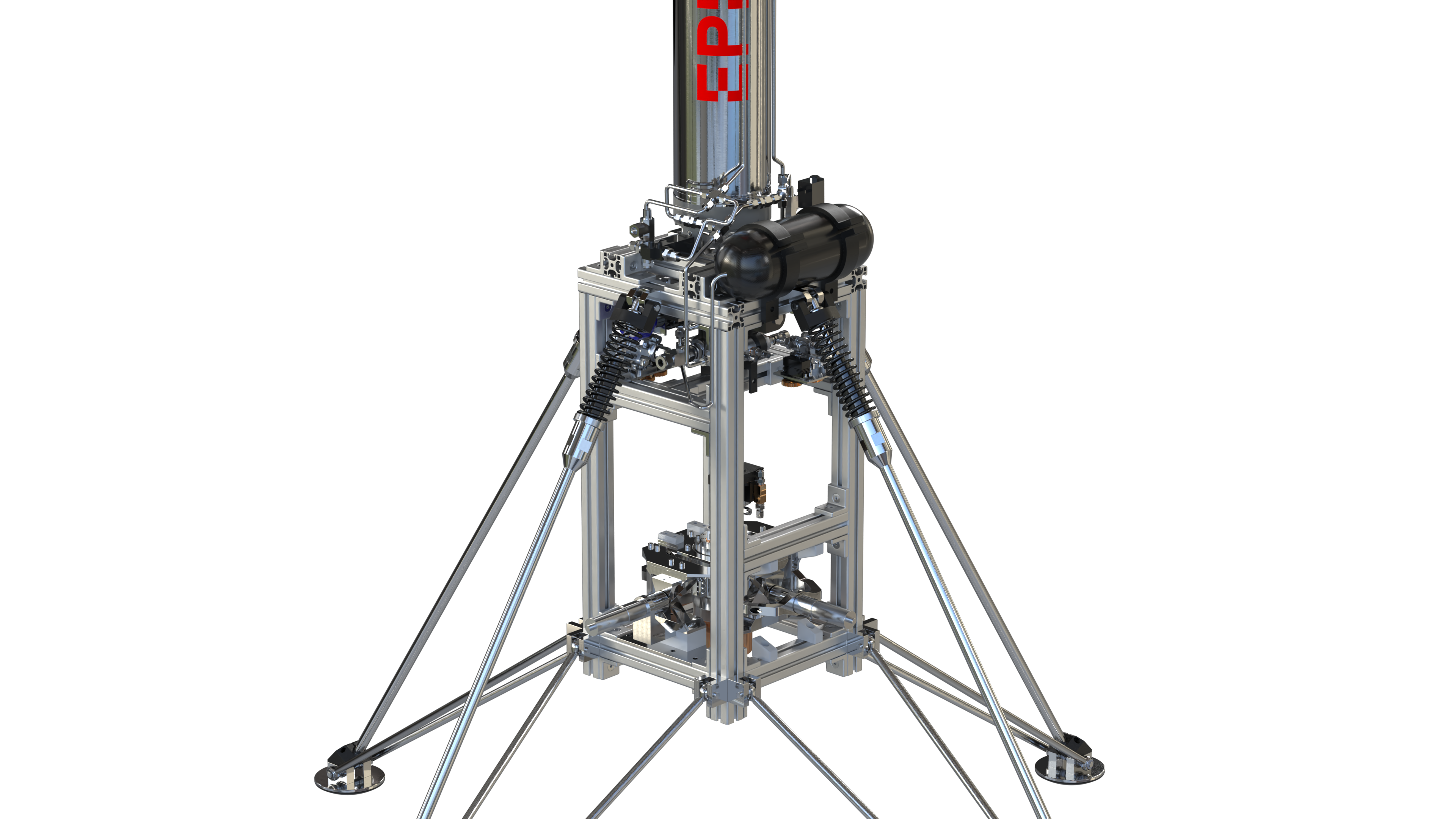
¶ Launch Vehicle Overview
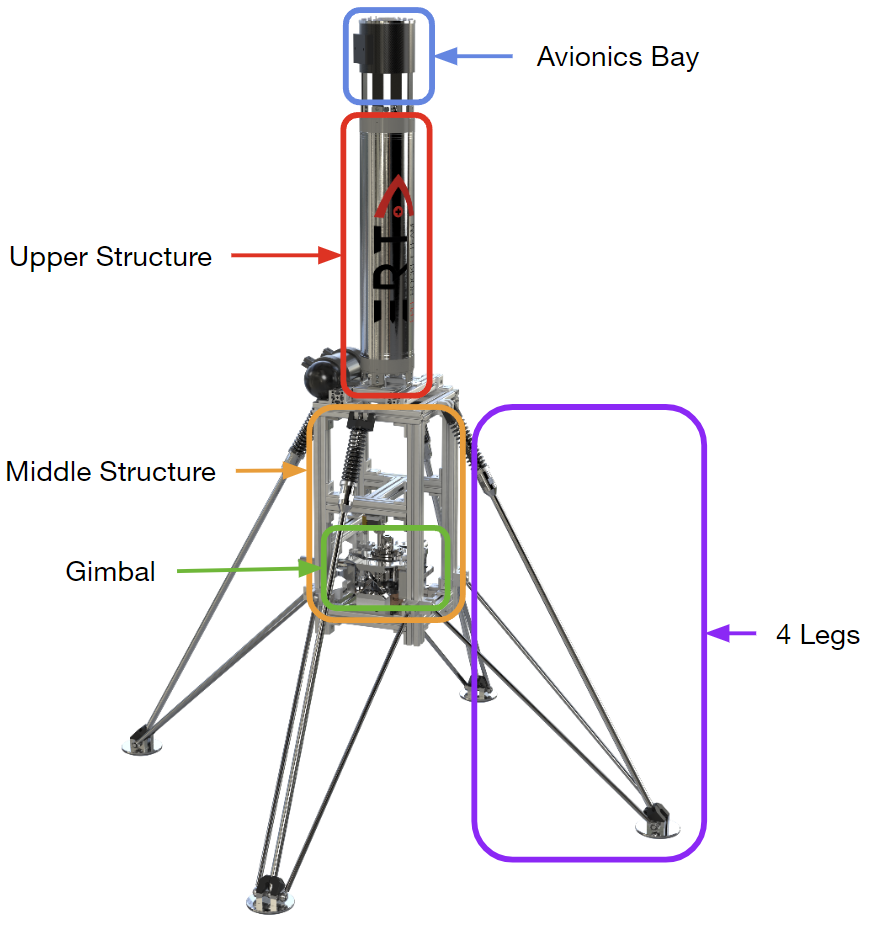
The main function of the structure of the hopper is to link all the parts and subsystems (AV and PR) of the launch vehicle together. The other main function is to assure the protection of the subsystems against the elements and loads. The hopper is seperated into 4 main sub-assemblies:
1. The upper structure: consists of Nordend's backup coaxial tank and of the Avionics bay (where the main sensors stay)
2. The middle structure: composed of an assembly of aluminium profiles. The middle ST connects to all the other sub-assemblies.
3. The gimbal: has the function of holding and guiding the rocket engine DEMO-A3 to achieve the thrust vector control (TVC) necessary to have a stable flight.
4. The Legs : necessary for absorbing the shock of the landing event composed of a damper and spring system
Here is an overview of the current 2024 launch vehicle that has been manufactured.
¶ Sub-sub-assemblies Tree & Nomenclature
As there are over 900 parts on the main Hopper assembly, this tree won't show all the parts but just the sub assemblies of the sub assemblies. It also shows the nomenclature followed to name our parts.
¶ COTS Parts Table
| Part Name | Number of Parts | Main Characteristics | Link to Data Sheet |
|---|---|---|---|
| I14103_Damper | x4 | Stroke = 75mm, Adjustable damping coefficient 300-~300 000 [Ns/m] | Weforma_WE-M 1,25 |
| I14113_Spring | x4 | De = 45mm , L0 = 205, C = 7.94 N/mm, Ln = 81mm | CA 5.00/205.00 on Ressorts du Léman |
| Maxon actuators | x2 | 1:103 Reductor gives : Max nominal torque of 14 [Nm] and Max speed : 6000 [rpm] | Part_3_Datasheet |
| I11303_Oldham_Coupling | x2 | Admissible lateral movement : 2.5 [mm], Outer diameter : 35[mm], Axle diameter : 8 [mm] | MCZ-35-8X8C Coupling |
¶ SRAD Sub assembly Description
¶ Gimbal
The best way to understand the compliant gimbal is to first read the corresponding paper done for the 2023 IAC conference: Flexure-based gimbal with high support stiffness for rocket thrust vector control
This paper regroups all necessary formulas to easily characterise and dimension a flexure based gimbal from the stiffness to the compression or traction force put on a pivot.
A more detailed wiki file on the gimbal can be found in the Gimbal DDF.
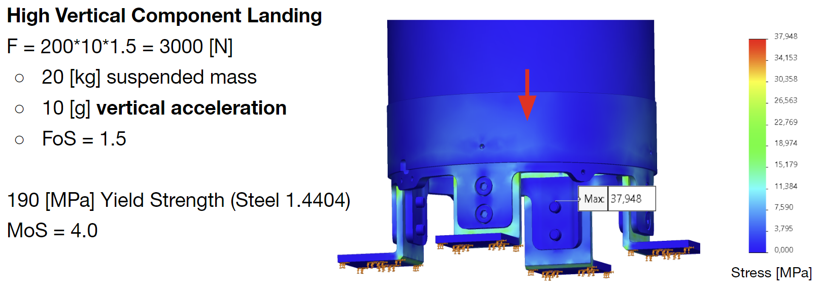
¶ Legs
A more detailed wiki file on the legs can be found in the Legs DDF.
¶ AV Bay
The avionics bay has the purpose to hold the avionics boards.
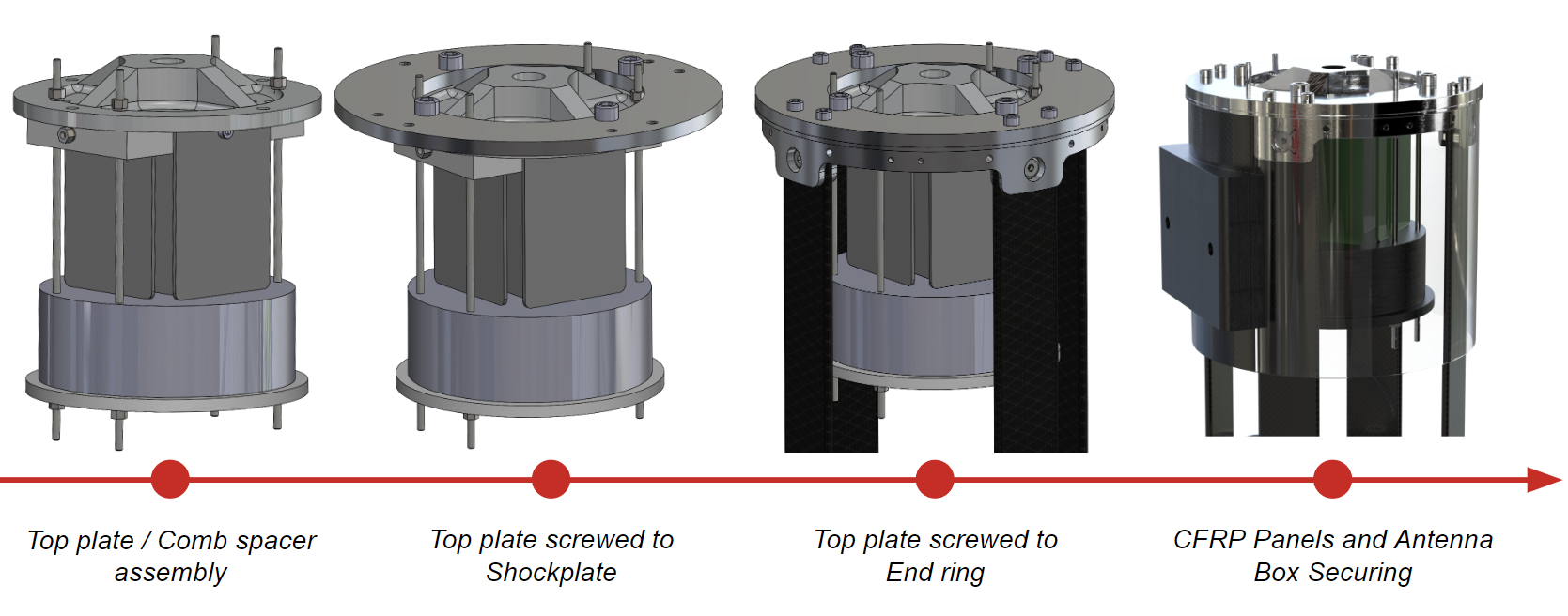
A more detailed wiki file on the AV bay can be found in the Upper structure DDF.
¶ Upper Structure
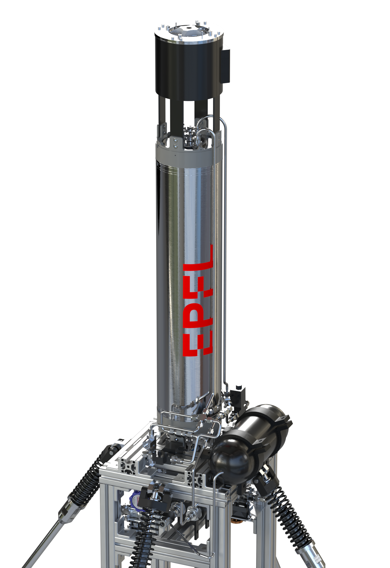
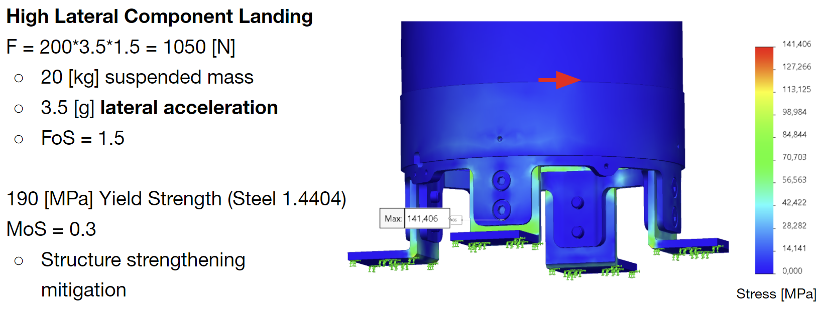
Nordend's tank is fixed to the middle structure using 4 steel brackets. Here are the simulations related to the two axial and radial acceleration loads. The axial simulation has a relatively high margin of safety but the radial load has a quite small margin of safety. This problem could be mitigated by a few solutions; the material could be replaced by a stronger steel with higher yield strength, or the tank could receive bracing with either a structure around it or cables going down to anchor points on the middle structure.
A more detailed wiki file on the Upper Structure can be found in the Upper structure DDF.
¶ Middle Structure
A more detailed wiki file on the Middle Structure can be found in the Middle structure DDF.
¶ Interfaces
The structure part of the hopper has two main interfaces with AV and PR:
The Structure has to hold the main Avionics boards which are in the AV Bay. Then cables run down to a box filled with LiPo batteries and actuator boards (for the gimbal and propulsion). Here is the LLIM with AV:
There are multiple interfaces with the Hyperion Class A rocket engine and plumbing:
- 2024_I_ST_AC_PHY_LLIM_01 Gimbal-Engine Interface
- 2024_I_ST_AC_PHY_LLIM_02 Plumbing Mounting
- 2024_I_ST_AC_PHY_LLIM_03 Plumbing-Tank Interface
¶ Technical Budget, Margins and Deviation
Costs budgets document can be found in 2024_I_SE_BUD.
Length and mass budgets document can be found in 2024_I_SE_LVS.
| Type of value | Units | Actual Value | Requirement Value | Deviation |
|---|---|---|---|---|
| AV Bay | kg | 2.400 | ||
| Upper Structure | kg | 9.800 | ||
| Middle Structure | kg | 15.600 | ||
| Legs | kg | 15.560 |
¶ Design Constraints
¶ Constraints for Production
155 mechanical parts that needed to be machined compose this Hopper ! As these parts were machined by students at the SPOT, this created a need for a production planning so not too many ERT students occupied the machining workshop at once. This document can be found in this document: 2024_I_PRODUCTION-TRACKER. It is advised to use such a document to keep track of which parts are left to machine. This is also a good to not upset Ivan, the mechanical coach.
A maximum of complex curves were made in 5mm thick aluminium plates so these could be laser cut on the laser at the SPOT. Even though the laser had problems, this simplified the production for certain parts.
¶ Constraints for Operation
¶ Transportation
The legs of the hopper can be taken off or can take much less space by removing 8 circlips off of the lower struts of the legs. This allows easy transportation of the dissassembled Hopper. A tool is planned to be designed to more easily remove the legs without the Hopper falling to the ground. This tool should have wheels to easily move the Hopper around.
¶ First flight
When the Hopper will first fly, it is planned to do so attached to a crane. This forced the addition of an eyebolt to the top of the hopper. Calculations were also done to make sure the parts connecting the eybolt to the structure would also hold the stresses.