¶ Introduction
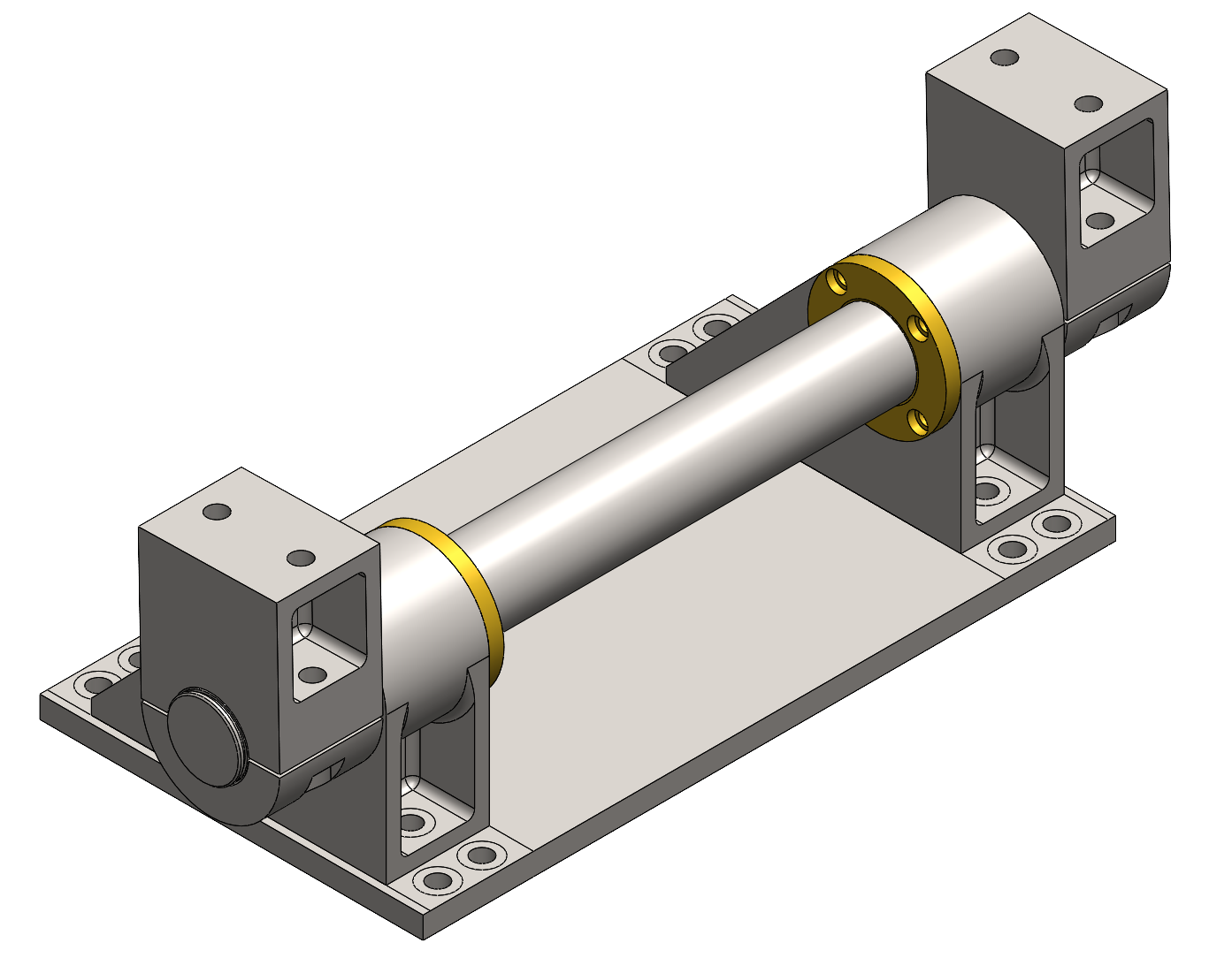
The objective of this Finite Element Analysis Report (FEAR) is to present the results of the mechanical performance of the Hub's pivot.
The geometry and dimensions of the pivot components were refined at the part level throughout the simulations. However, to improve readability, this document presents the simulation of the full assembly, which provides a clear understanding of the overall performance without compromising the accuracy of the results.
The analysis was conducted using SolidWorks Simulation with the Static Simulation plugin.
While the pivot is subjected to multiple load cases (such as compression during wind loading or shear during hoisting) it was found that the worst case one was the Vertical Static Fire test one. Thus we will focus on the result of the simulation regarding this scenario.
¶ Load Case
During Vertical Static Fire Tests the pivot is subjected to excessive loads from the engine thrust.
Using the analysis made in 2025_SH_GS_SLRS_HU_FRAME_FEAR we yield the following load :
| Force | Value |Unit|
|---------------------|-------------------------|
||100 000 |[N]|
¶ Inputs
The material used for the simulations is Stainless Steel 1.4301 (AISI 304) that provides a yield limit of 210 [MPa] with a young modulus of 193 [GPa]
| Assembly Name | Configuration |
|---|---|
| pivot.SLDASM | vsft |
All fasteners have been removed. Although the simulation could have been conducted on half of the pivot assembly due to the symmetry of the load case, the SolidWorks Simulation tool did not support this approach.
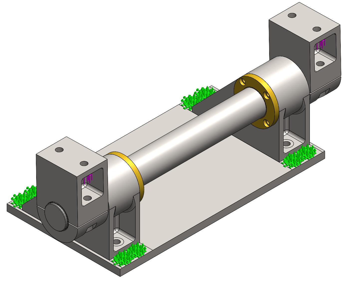
| Boundary Condition | Type | Location |
|---|---|---|
| 1 | Anchored | Hub bolts contact surface |
The bolted connection beetween the interface plate and the hub frame is considered as anchored.
A global united interaction was set on the assembly components.
| Force | Value | Unit | Location |
|---|---|---|---|
| 1 | 100000 (total) | [N] | Tower segment 1 bolts contact surface |
The forces are applied on tower segment 1 bolts contact surface.
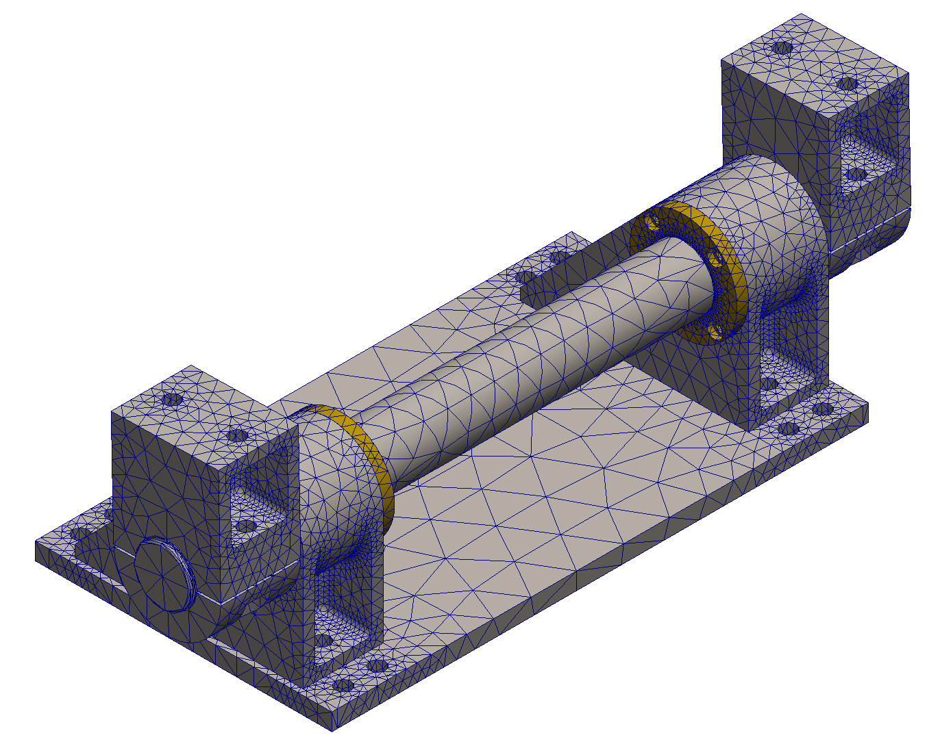
¶ Mesh
| Type | Control |
|---|---|
| 3D Tetrahedric | Program controlled |
| Mesh | Size | Unit | Location |
|---|---|---|---|
| Global | 2 to 40 | [mm] |
¶ Outputs
| Max Stress [MPa] | Min MoS | Max Displacement [mm] |
|---|---|---|
| 144 | 0.45 | 0.32 |
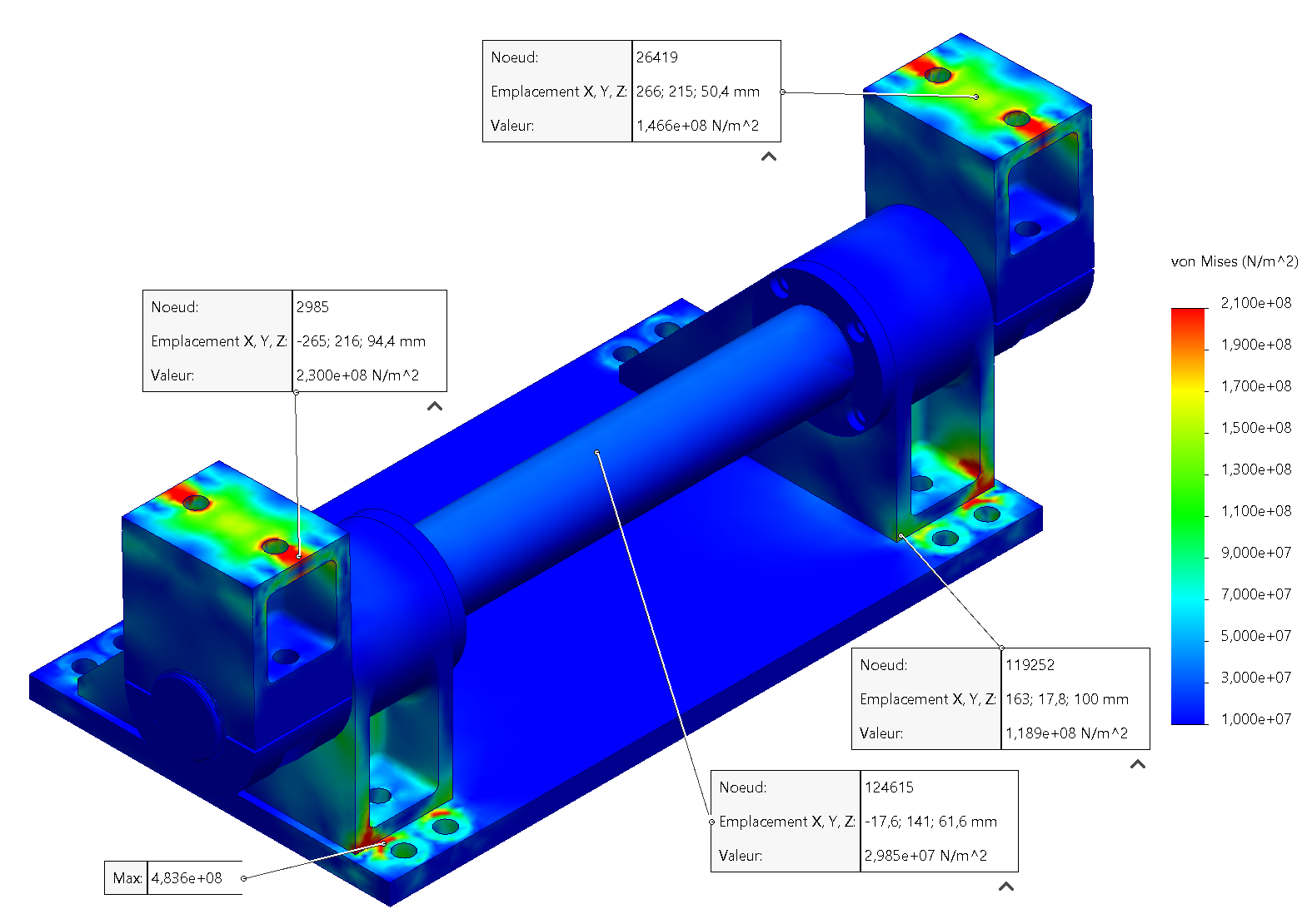
| Stress [MPa] | MoS [-] | Location | Node Number |
|---|---|---|---|
| 144 | 0.45 | Female support | 26419 |
| 110 | 0.9 | Male support | 119252 |
We observe high stress near the bolts heads, these peaks can be ignored as when the mesh is refined (in other part specific simulations) the values lower down to positive MoS.
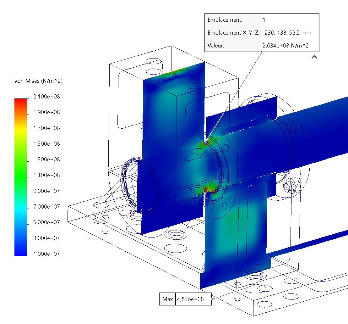
We observed a peak stress significantly exceeding the material's yield limit near the circlip housing. To investigate whether this value was due to a mesh-related issue (divergence), we conducted additional simulations specifically on the axis. The results of which are here under.
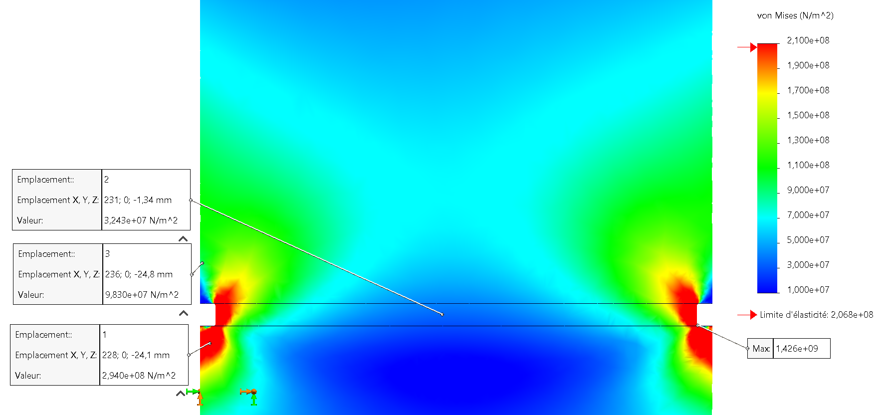
We observed that by reducing the mesh size around the circlip housing, the peak stress increased exponentially, rising from 263 MPa to 1426 MPa. This indicates that the peak stress near the circlip housing is likely a simulation anomaly.
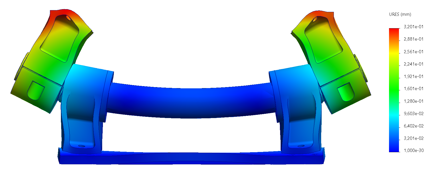
| Displacement [mm] | Location |
|---|---|
| 0.32 | Female support |
The displacement is low and we can consider it a worst case scenario as our analysis does not take into account the interaction beetween the female supports and the tower interface plate, that would lower the peak displacement drastically.
¶ Interpretation
The FEA indicates that the yield limit is exceeded at the circlip junction. However, based on the axis diameter analysis performed in 2025_SH_GS_SLRS_HU_DDF and the mesh convergence studies specifically conducted on the axis component, it is reasonable to regard this as a simulation anomaly.
It should also be noted that the 263 [MPa] peak stress is still under the 700 [MPa] ultimate stress of the S.S. 304 material used, thus even if our assumptions are incorrect it should only translate to minor plastification of the axis' surface.
Except the anomalies all stress values stay under control on all parts, yielding positive safety margins, even with the comprised safety factor of 2.
Regarding the displacement, they are very low at a peak of 0.328 [mm], indicating a rigid pivot.
¶ Conclusion
Based on the analysis performed on the pivot under Vertical Static Fire Test loads, we can conclude that the pivot is compliant with the load cases it will encounter during operation.