¶ Introduction
The purpose of this document is to explain the main objectives, constraints, interfaces, and finally the design of the AIS.
The design must be conceived in such a way as to answer the following questions:
- Who is it intended for?
- Does it withstand the constraints it is subjected to?
- Is it optimal in terms of mass, and does it meet the self-imposed pre-criteria?
- Does it avoid interference with other modules and components of the system?
This document therefore covers the St-Av and St-Pl interfaces.
It will also explain the choice of materials as well as provide a list of the different assembled components.
This document does not cover the internal structure corresponding to carbon rods,anti-buckling rings and shockpler interface
¶ Definitions and Abbreviations
- AIS:
- St: Structure
- PL: Payload
- Av: Avionics
¶ Applicable and Reference Documents
The following documents detail other aspects of this assembly and may provide important elements for understanding this DDF.
¶ Requirements
The AIS is the principal module of the avionics bay. It is used for the installation of different PCBs and a camera.
- Must accommodate four PCBs measuring 100 × 100 mm
- Must accommodate two smaller PCBs measuring 24x24 mm
- Must accommodate a spine connecting the four PCBs
- Must accommodate a battery of 95x85x74 mm and weighing 0,9 kg
- Must provide cable management capability
- Each PCB must be removable and replaceable within 5 minutes on the rocket once the panels are removed
- Must accommodate the Payload module with an upward-facing camera
- Must be as compact as possible
- Must not exceed the mass limit
- Must withstand loads of 30 g
¶ Interfaces
All interface issues and constraints are described in the following document:
¶ Overview
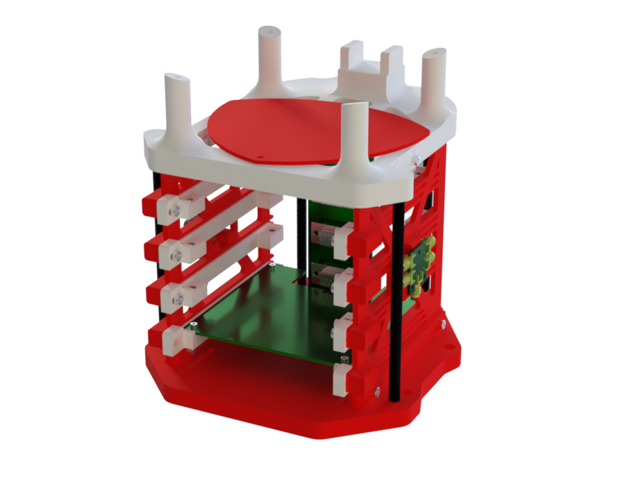
The AIS structure is composed of the following components:
| Component | Quantity |
|---|---|
| Top_Cover | 1 |
| Top_Plate | 1 |
| Walls | 2 |
| Carbon Bars | 4 |
| Sliders | 8 |
| Bottom_Plate | 1 |
| Ais-Camera | 1 |
The entire assembly is secured using M3 screws, 3D-printed inserts, and self-locking nuts.
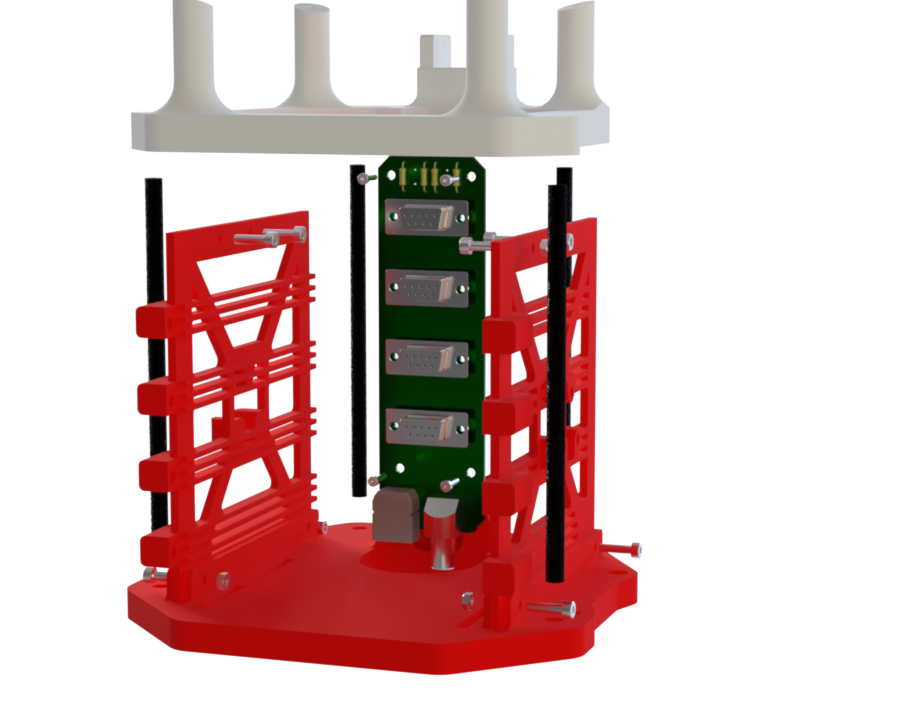
- The spine is secured using four 3D-printed inserts and four screws: two attached to the top plate and two to the base.
- The two wall pieces are attached to the base using two screw–nut assemblies on each side, and then fastened to the top plate with the same number of screws.
- Tensile strength is enhanced by the addition of four hollow carbon bars, bonded using Loctite Blue adhesive.
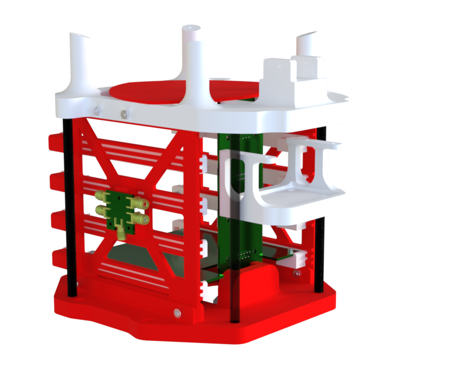
- Each of the four overhangs on the walls is pre-fitted with 3D-printed inserts and two sliding rails for each PCB.
- The rails allow each PCB to slide along the wall, and the assembly is locked in place with two M3 screws per PCB, secured into the wall.
- The smaller PCBs can be mounted on the sides of the wall using three M2 screws.
- A cover can be added on top of the module to protect the PCBs and fixed with one M2 screws.
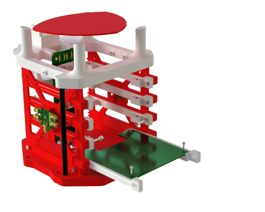
- Under the Top_Plate, a part called AIS-camera is fixed, which allows the PL module to be mounted.
- On the Top_Plate, there is also an area that can be used for mounting the module.
¶ Parts Description
Most of the parts are 3D-printed to facilitate the manufacturing of complex geometries
Regarding load constraints, it is assumed that the carbon reinforcement bars are more than sufficient to support the loads from the battery and the PCBs -->
The only part that requires verification through simulation is the top plate
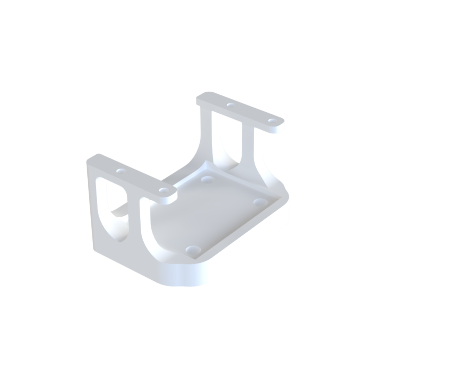
¶ Description
Function:
Supports the payload and its camera, as well as the walls, carbon bars, and the spine.
It is attached to shockpler with 4 through screw and bolts.
Mechanical properties:
This part is the most stressed component, so it is made with 12 perimeter layers and very little infill to ensure high torsional resistance.
Additional features:
We can add a top cover to ensure that no components from the Re Bay interfere with the PCBs.
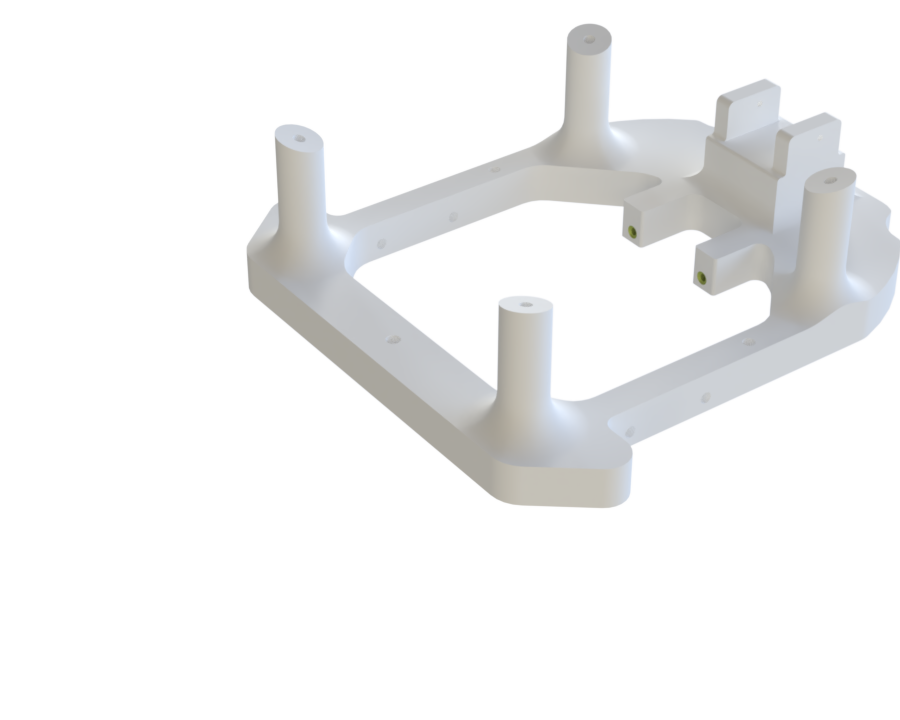
¶ Main Specifications
| Specification | Value | Unit |
|---|---|---|
| Dimensions | 46 x 152 x 162 | [mm] |
| Mass | ? | [g] |
| Manufacturing | 3D Printer | x |
| Fastening | 4x M3 to shockpler | x |
¶ Interfaces
- Four M4 inserts on the top are used to attach the camera payload.
- Two inserts are used to attach the front spine.
¶ Description
Function:
Supports the battery and the spine, and is attached to the wall as well as to the carbon bars using blue epoxy adhesive.
Mechanical properties:
The only stress applied is from the weight of the battery, with no significant deformation observed.
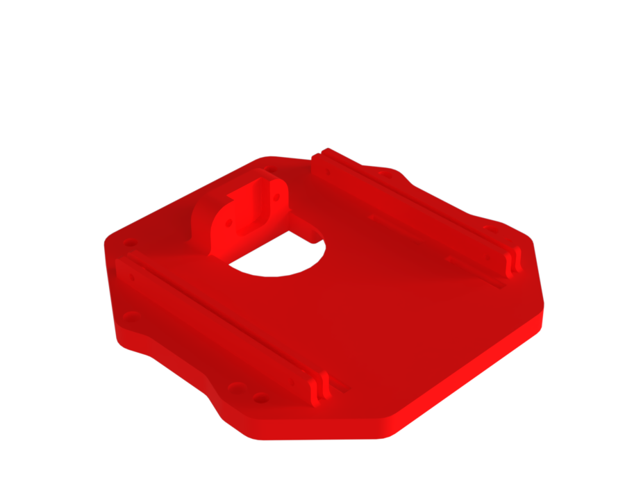
¶ Main Specifications
| Specification | Value | Unit |
|---|---|---|
| Dimensions | 10 x 158 x 160 | [mm] |
| Mass | ? | [g] |
| Manufacturing | 3D Printer | |
| Fastening | 4x M3 to wall + 4 glued carbon bar to Top_PLate | x |
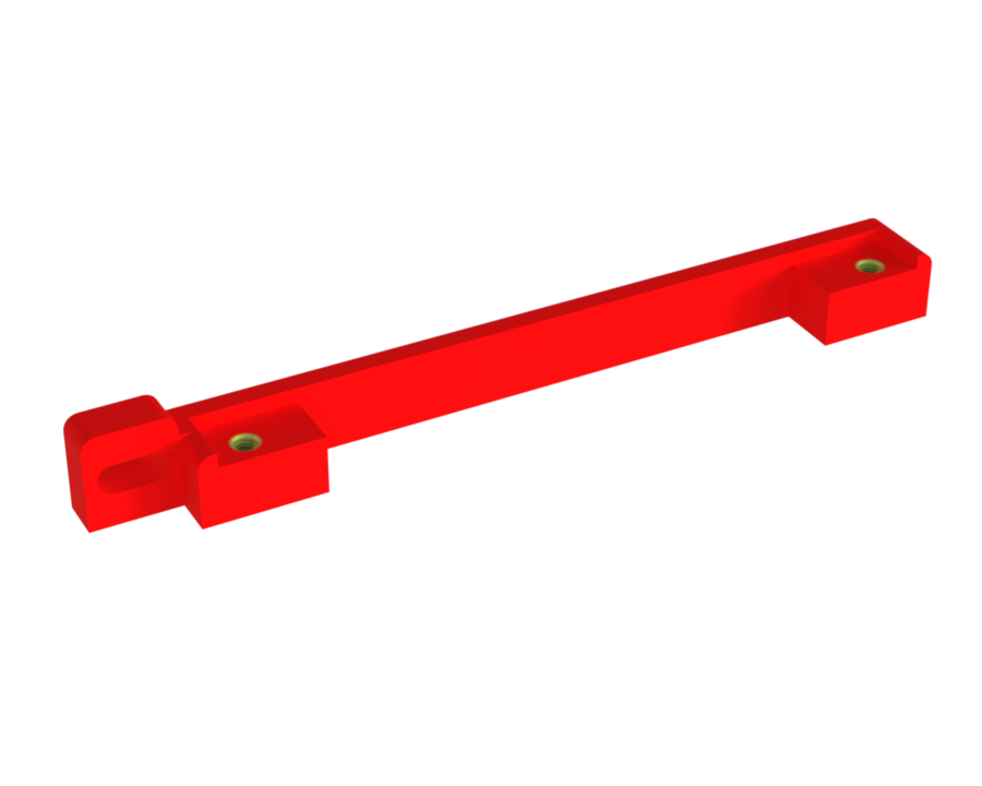
¶ Interfaces
-Two M3 inserts for the front spine.
¶ Description
It is used to protect the PCBs in case the nut falls during screwing.
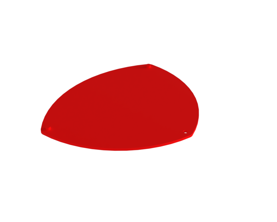
¶ Main Specification
| Specification | Value | Unit |
|---|---|---|
| Dimensions | 3 x 100 x 120 | [mm] |
| Mass | ? | [g] |
| Manufacturing | 3D Printer | x |
| Fastening | 2 fittings and 1 M2 screw on the Top_Plate | x |
¶ Description
Function:
Serves as a guide for the PCB sliders. Both parts are symmetrical to each other and are attached to the bottom plate and the top plate with four M3 screws each.
Mechanical properties:
They do not take any or few tensile load, as this is supported by the carbon bars.
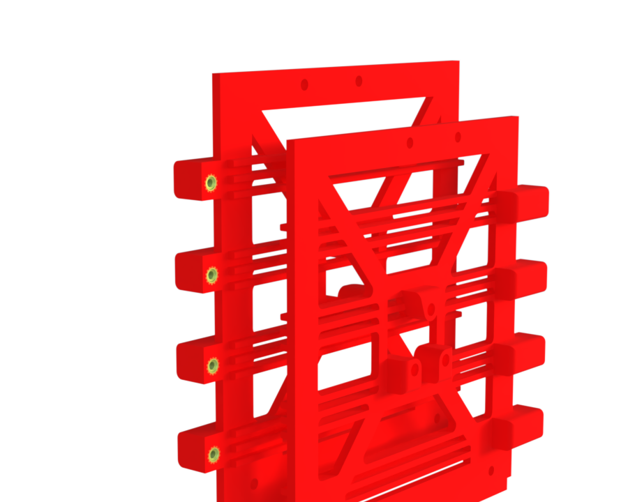
¶ Main Specifications
| Specification | Value | Unit |
|---|---|---|
| Dimensions | 3 x 35.4 x 126 | [mm] |
| Mass | [g] | |
| Manufacturing | 3D Printer | x |
| Fastening | 4x M3 to the Bottom_Base and 4x M3 to the Top_Base | x |
¶ Interfaces
- Eight M4 inserts at the front are used to attach the 4 sliders of PCB AV.
- Two inserts on the side are used to attach 2 smalls PCB.
¶ Description
Function:
Used to guide the PCB along the wall rails. They can be secured with two M3 screws to prevent any backward sliding.
¶ Main Specifications
| Specification | Value | Unit |
|---|---|---|
| Dimensions | 10 x 11.6 x 117 | [mm] |
| Mass | ? | [g] |
| Manufacturing | 3D Printer | x |
| Fastening | 2x M2 to PCB + 1x M3 to Wall | x |
¶ Interfaces
- Two M3 inserts to secure the PCBs. Each PCB therefore has two sliders.
¶ Technical Budget, Margins and Deviation
All printing budgets are managed directly by the Spot’s printing service through the website Spot 3d Printing.