¶ Introduction
The purpose of this document is to explain the arrangement of the avionics bay, its components, and the constraints it faces.
The interfaces of this bay are St-PL, St-Av, and St-St, as it involves the AIS and the bay with its rods and coupler.
Simulations, as well as the arrangement and design of the AIS, will not be addressed in this document.
¶ Definitions and Abbreviations
- AIS:
- St: Structure
- PL: Payload
- Av: Avionics
¶ Applicable and Reference Documents
The following documents detail other aspects of this assembly and may provide important elements for understanding this DDF.
They include an LLIM to understand the different interfaces, and the DDF of the AIS to understand its structure.
¶ Requirements
- Must be able to hold 8 aluminum antennas between the rods, with dimensions … × … mm.
- Must facilitate access to the AIS after removal of the panels and antennas.
- Must not obstruct the Avionics electrical cables.
- Must allow the Payload camera to film the separation of the mechanism.
- Must support the weight of the AIS.
- Must axially and radially lock the AIS.
- Must not exceed mass budget.
¶ Interfaces
¶ Interface ST_AV
- ⬛Physical interface:
The Avionics Bay is crossed by numerous electrical cables. It must therefore facilitate cable management and must not obstruct their access.
¶ Interface ST_PL
- ⬛Physical interface:
The arrangement of the Avionics Bay must not prevent the payload camera module from recording the deployment of the recovery system.
¶ Interface ST_GS
- ⬛Physical interface:
The avionics bay, in addition to supporting the AIS, must also hold 8 flat antennas mounted on the ABR and on 3D-printed MPS brackets. The antennas are connected to the AIS. - 🟦Information interface:
To allow the antennas to properly receive signals without interference, the panels of this bay are made of fiberglass instead of carbon.
¶ Interface ST_RE
- ⬛Physical interface:
The AIS–Shockpler assembly must allow the M8 ring bolts to be properly installed and screwed in place.
¶ Interface ST_ST
- ⬛Physical interface:
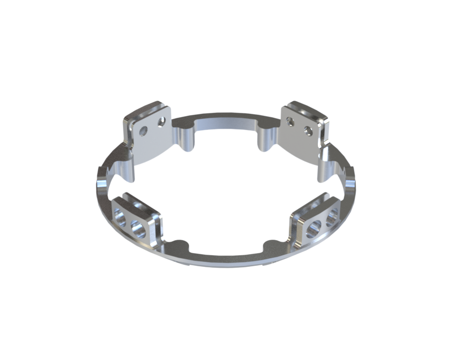
The avionics module must be correctly connected to the separation mechanism through the Shockpler, as well as to the pressurant bay via its male coupler.
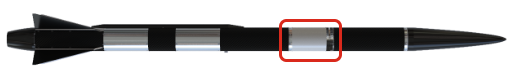
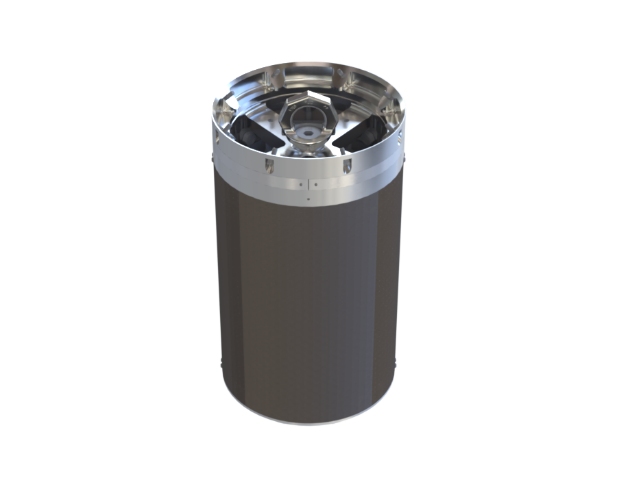
¶ Overview
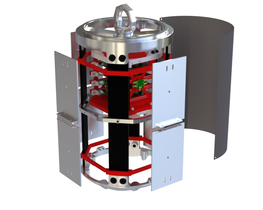
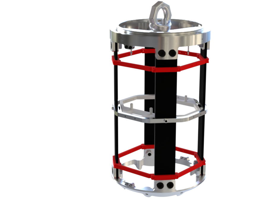
¶ Internal Structure
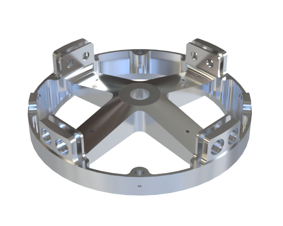
The Avionics Bay is very similar to the others: it includes 4 rods, a male coupler, and an ABR screw together.
It differs in the following aspects: it contains a Shockpler to connect it to the separation mechanism, and its panels are made of fiberglass.
¶ Lower Level :
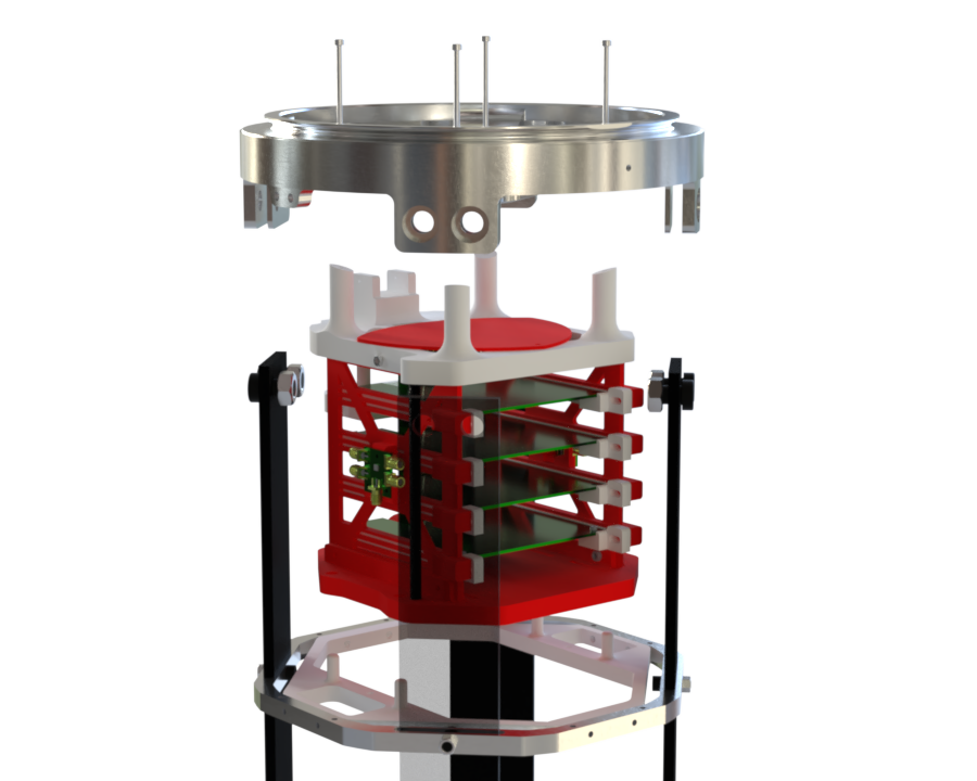
- The AIS is bolted to the Shockpler using 4 long through-bolts, together with nuts and washers, in order to constrain it axially.
- The angular orientation of the AIS will depend on the Payload team’s choice regarding what they want to record.
- The AIS is radially constrained by the following assembly: a 3D-printed ring is fixed to the ABR and interlocks with it at 4 points beneath the module.
- The antennas are mounted on the ABR and the MPS: inserts with nuts are used for the MPS, while standard nut-and-bolt fasteners are used for the ABR.
- The M8 ring is screwed on top of the Shockpler using an M
¶ Parts Description
Here is its composition diagram:
- For any description regarding the shockpler or coupler, please refer to the following page
- For any description regarding Internal Structure, please refer to the following page
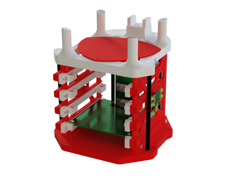
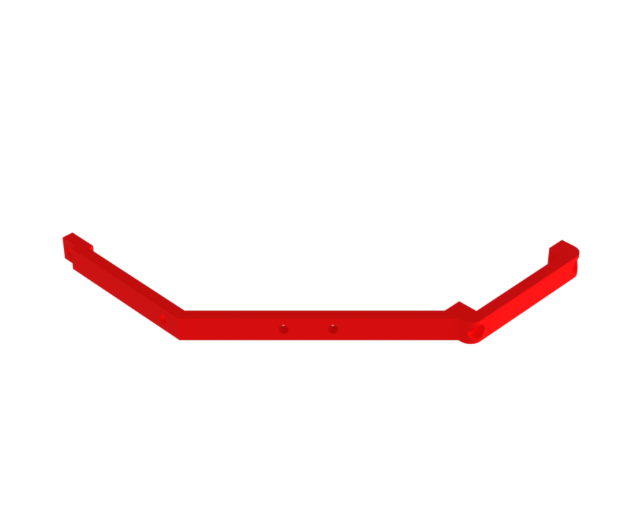
¶ Description
- The purpose of these MPS is to attach the GS/AV antennas to the Avionics Bay.
They are placed on either side of the module — 4 on the top and 4 on the bottom — and once screwed in, they form a closed ring. - They are 3D-printed and equipped with M3 threaded inserts.
¶ Main Specifications
| Specification | Value | Unit |
|---|---|---|
| Dimensions | [mm] | |
| Mass | [g] | |
| Manufacturing | 3D Print | |
| Fastening |
¶ Interfaces
- They have an interface with GS/AV: the antennas are mounted with M3 screws using 2 inserts on each of the 8 MPS segments.
.png)