¶ Introduction
Rocket fins play a vital role in the stability and control of rockets during flight. These aerodynamic surfaces are typically located at the tail end of the rocket and are designed to generate forces that counteract any unwanted motion, such as roll, pitch, or yaw. Fins provide stability by creating aerodynamic forces that help maintain the rocket's desired trajectory and prevent it from veering off course.
This Design Justification File (DJF) aims to present the rationale for the selection of the fins structural design, and to demostrate that the choice meets the baseline requirements.
¶ Definitions and Abbreviations
- DJF: Design Justification File
- ERT: EPFL Rocket Team
- FD: Flight Dynamic team
- FE: Finite Element
- FEA: Finite Element Analysis
- FoS: Factor of Safety
- RF: Reserve Factor
- MoS: Margin of Safety
¶ Relevant Knowledge Needed
¶ Fins design
The fin design must be optimized to balance sufficient stability with minimal drag. Several factors influence rocket fin design, including planform shape, geometry, aspect ratio, and cross-section. Common planform shapes for high-powered and experimental sounding rockets include clipped delta, trapezoidal, and elliptical. The optimal planform shape varies based on the rocket's intended flight speeds. (FALEY EMMA)
One of the most important consideration when designing a fin is fin flutter, or bending-torsion flutter. It happens when torsional vibrations generate lift forces that match or exceed the damping forces from bending vibrations. When these damping forces are insufficient, the oscillations intensify, ultimately leading to the destruction of the fins. (Ramsey, J. K., ed., “NASA Aeroelasticity Handbook Volume 2: Design Guides Part 2,” NASA Technical Reports Server [online], NASA/TP-2006-212490-VOL2-PT 2, E-14035, November 2006, https://ntrs.nasa.gov/archive/nasa/casi.ntrs.nasa.gov/20070008370.pdf [retrieved July 2018].)
 https://www.youtube.com/watch?v=pyct1Pii_cg
 https://wikis.mit.edu/confluence/display/RocketTeam/Fin+Can+Design
¶ Previous work at the ERT
- Geometry: trapezoidal
- Material: CFRP
- Fixation: plates clamped using aluminium rings
- Speed regime: subsonic
- Geometry: trapezoidal
- Material: CFRP sandwich with epoxy foam
- Fixation: part of the airframe
- Speed regime: supersonic
- Geometry: trapezoidal
- Material: CFRP
- Fixation: part of the airframe
- Speed regime: subsonic
¶ Requirements
- 2024_C_SE_ST_ENGINE-BAY_REQ_09 Fins loads bearing - Radial force
The fins fixation points shall withstand radial forces caused by the fins of up to [TBD]N with a FoS of [2]. - 2024_C_SE_ST_ENGINE-BAY_REQ_18 Fins loads bearing - Axial force
The fins fixation points shall withstand axial forces caused by the fins of up to [TBD]N with a FoS of [2]. - 2024_C_SE_ST_ENGINE-BAY_REQ_19 Fins loads bearing - Bending moment
The fins fixation points shall withstand bending moments caused by the fins of up to [TBD]Nm with a FoS of [2]. - 2024_C_SE_ST_ENGINE-BAY_REQ_11 Engine bay structure mass
The total mass of the Engine Bay structure shall be maximum [7000]g.
¶ Structural interfaces
The fins are mounted on the Engine-Bay.
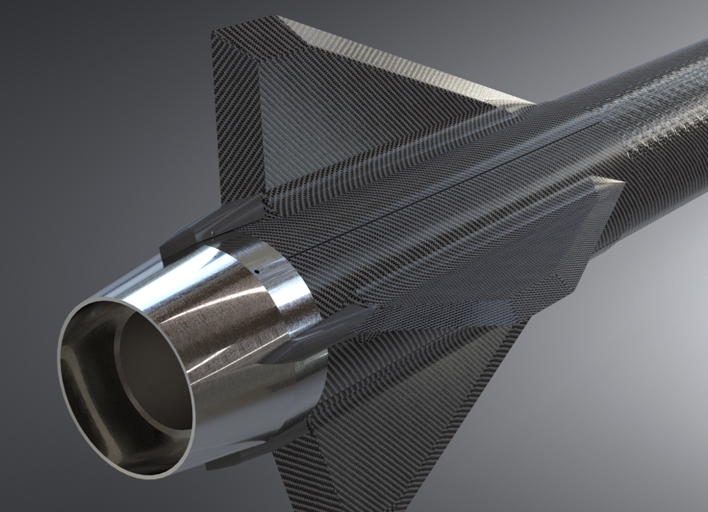
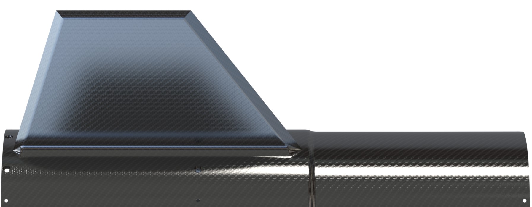
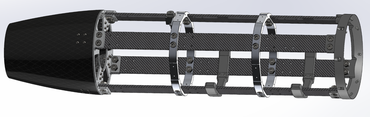
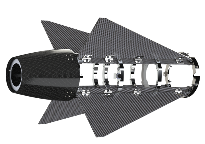
If the chosen design is similar to that of Wildhorn and Nordend, the fins will be attached the the mechanical parts at the end of the rods. If the chosen design is similar to that of the Bella Lui II, the fins shall be mounted on the rods and not between in order guarantee the radial access to the Engine-Bay. The airframe will then be composed of separate panels.
¶ Design Options
Fin flutter velocity is given by the formula:
(Martin, D. J., “Summary of Flutter Experiences as a Guide to the Preliminary Design of Lifting Surfaces on Missiles,” NASA Technical Reports Server [online], NACA-TN-4197, 1958, https://ntrs.nasa.gov/archive/nasa/casi.ntrs.nasa.gov/19930085030.pdf [retrieved July 2018].)
where,
- : aspect ratio (semi-span2/fin area)
- : speed of sound
- : average of root chord and tip chord
- : effective shear modulus
- : air pressure at sea level
- : air pressure at altitude
- : fin thickness
- : taper ratio (ratio of tip chord to root chord)
Preventing fluttering means maximising the the flutter velocity. So, increasing the thickness and decreasing the aspect ratio of fins can reduce the risk of fin flutter.
Note that fluttering is linked to the natural frequencies. Maximising the flutter velocity is equivalent to maximising the natural frequencies.
Moreover, using multiple materials in fin construction reduces the likelihood of fin flutter. Each material has a distinct resonance frequency, preventing the fins from vibrating at a single frequency that could lead to failure.
(Simmons, J.R., “Aeroelastic Optimization of Sounding Rocket Fins,” Defense Technical Information Center
[online], June 2009, http://www.dtic.mil/dtic/tr/fulltext/u2/a502110.pdf [retrieved July 2018].
[)
CFRP sandwich is an appropriate material as it is light and stiff.
¶ Lay-up conception flow-chart (ad-hoc)
¶ Preliminary lay-up
Some preliminary lay-ups are studied in order to identify the pattern of composite properties.
Prepregs
| Denomination | Prepreg | Type | Thickness [mm] |
|---|---|---|---|
| a | 8552/40%/160WUD/AS4C-3K | UD | 0.13 |
| b | 8552S/37%/280H5/AS4-3K | Plain | 0.289 |
Core
- Material: ECA C2-3.2-29 (aramid honeycomb)
- Denomination: C
- [kg.m-3]
Geometry
- Root chord = [mm]
- Tip chord = [mm]
- Height = [mm]
- Sweep length = [mm]
- Sweep angle = [°]
- Targeted thickness = [mm]
Lay-up
Software: Altair EsaComp
Due to software limitation, the fin is approximated to a rectangle with identical root and tip chord.
Boundary condition: clamped at the root chord
| Core [mm] | 1.5 | ||||
|---|---|---|---|---|---|
| Lay-up | [ [0ₐ,45ₐ,90ₐ,-45ₐ,0ₐ]₂,C ]ₛₒ | [0_b[45ₐ,0ₐ,-45ₐ,0_b]ₛₒ,C]ₛₒ | [0_b,0ₐ,45ₐ,90ₐ,-45ₐ,0ₐ,0_b,C]ₛₒ | [0_b,0ₐ,45ₐ,0ₐ,-45ₐ,0ₐ,0_b,C]ₛₒ | [0_b[0ₐ,90ₐ,0ₐ,45_b]ₛₒ,C]ₛₒ |
| ID | A | B | C | D | E |
| Thickness [mm] | 4.1 | 4.216 | 3.956 | 3.956 | 4.216 |
| Mass [g·m⁻²] | 4151.5 | 4323 | 3912.4 | 3912.4 | 4323.2 |
| Sizing Freq. [Hz] | |||||
| Flexural strength [MPa] | 668.1 | 616.92 | 605.37 | 599.7 | 688.85 |
| Core [mm] | 2.0 | |||
|---|---|---|---|---|
| Lay-up | [[0ₐ,45ₐ,-45ₐ,0ₐ]₂,C]ₛₒ | [[0ₐ,45_b,0ₐ]₂,C]ₛₒ | [0_b,0ₐ,45_b,0ₐ,0_b,C]ₛₒ | [0_b,45ₐ,0ₐ,-45ₐ,0_b,C]ₛₒ |
| ID | F | G | H | I |
| Thickness [mm] | 4.08 | 4.196 | 4.254 | 3.936 |
| Mass [g·m⁻²] | 3344.4 | 3516 | 3602 | 3105.3 |
| Sizing Freq. [Hz] | ||||
| Flexural strength [MPa] | 498.92 | 498.92 | 443.74 | 363.25 |
| Core [mm] | 3.0 | |
|---|---|---|
| Lay-up | [0ₐ,45_b,0ₐ,C]ₛₒ | [[0ₐ,45_b,0ₐ]₂,C]ₛₒ |
| ID | J | K |
| Thickness [mm] | 4.098 | 4.04 |
| Mass [g·m⁻²] | 1816.1 | 1730.2 |
| Sizing Freq. [Hz] | ||
| Flexural strength [MPa] | 189.92 | 178.48 |
¶ Clamps
For a design similar to that of Bella Lui II, clamps are necessary to assemble the fins to the rods.
The clamps are designed to minimise as much as possible the deflection () of a fin under normal load.
- Material: aluminium
 https://mechanicalc.com/reference/beam-deflection-tables
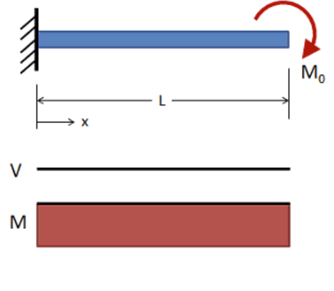
A clamp can be sized by modelling it using beam theory. In this case, it is modelled by a cantilever beam with end moment. In fact, the moment () applied to a clamp is the reaction moment due to a normal load applied on the tip chord of a fin.
The height () is chosen so that it does not exceed the height of a fin close to its leading edge. Therefore, the optimal clamp width () can be computed in function of the thickness ().
Maximum deflection is given by:
where,
The optimal width is then:
The maximum deflection was chosen arbitrarily for a fin. The one for a clamp was deduced with trigonometry: .
It is also important to verify that the maximum stress is not exceeding the yield strength of the clamp.
Inputs
| Fin | Clamp | |
|---|---|---|
| Height () [mm] | 240 | 20 |
| Deflection () [mm] | 6 | 0.50 |
| Number | / | 8 |
| Force () [N] | 2000 | / |
| Moment () [Nmm] | / | 5000 |
| Modulus () [MPa] | / | 70000 |
Outputs
| Thickness () [mm] | 1 | 1.5 | 2.0 | 2.5 | 3.0 |
|---|---|---|---|---|---|
| Inertia () [mm⁴] | 28.57 | ||||
| Width () [mm] | 342.86 | 101.59 | 42.86 | 21.94 | 12.7 |
| Stress () [MPa] | 87.50 | 131.25 | 175.00 | 218.75 | 262.50 |
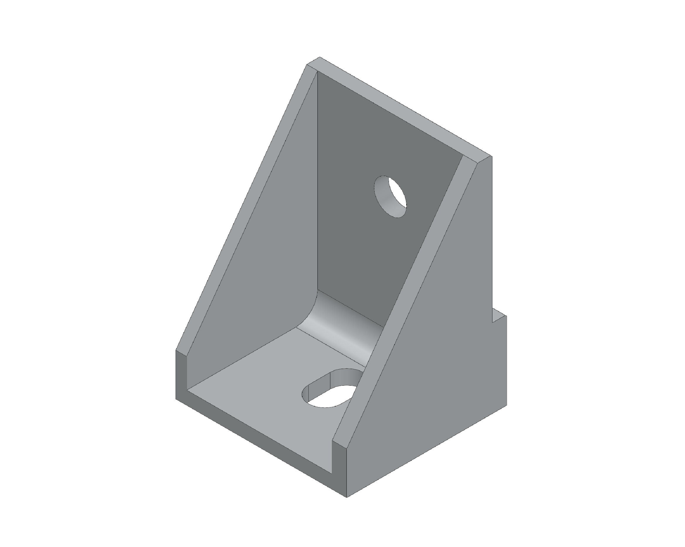
Clamp Single
The idea is to clamp a fin using two clamps assembled together using screws and nuts. Then, the base of the clamp is screwed to a CFRP rod using also a nut. The through-hole there has an oblong form to adapt to the fin's thickness irregularities while ensuring a good positioning.
The fin rests on top of stop, allowing the fixation of other parts to the rod.
The clamp also has two ribs for additional stiffness.
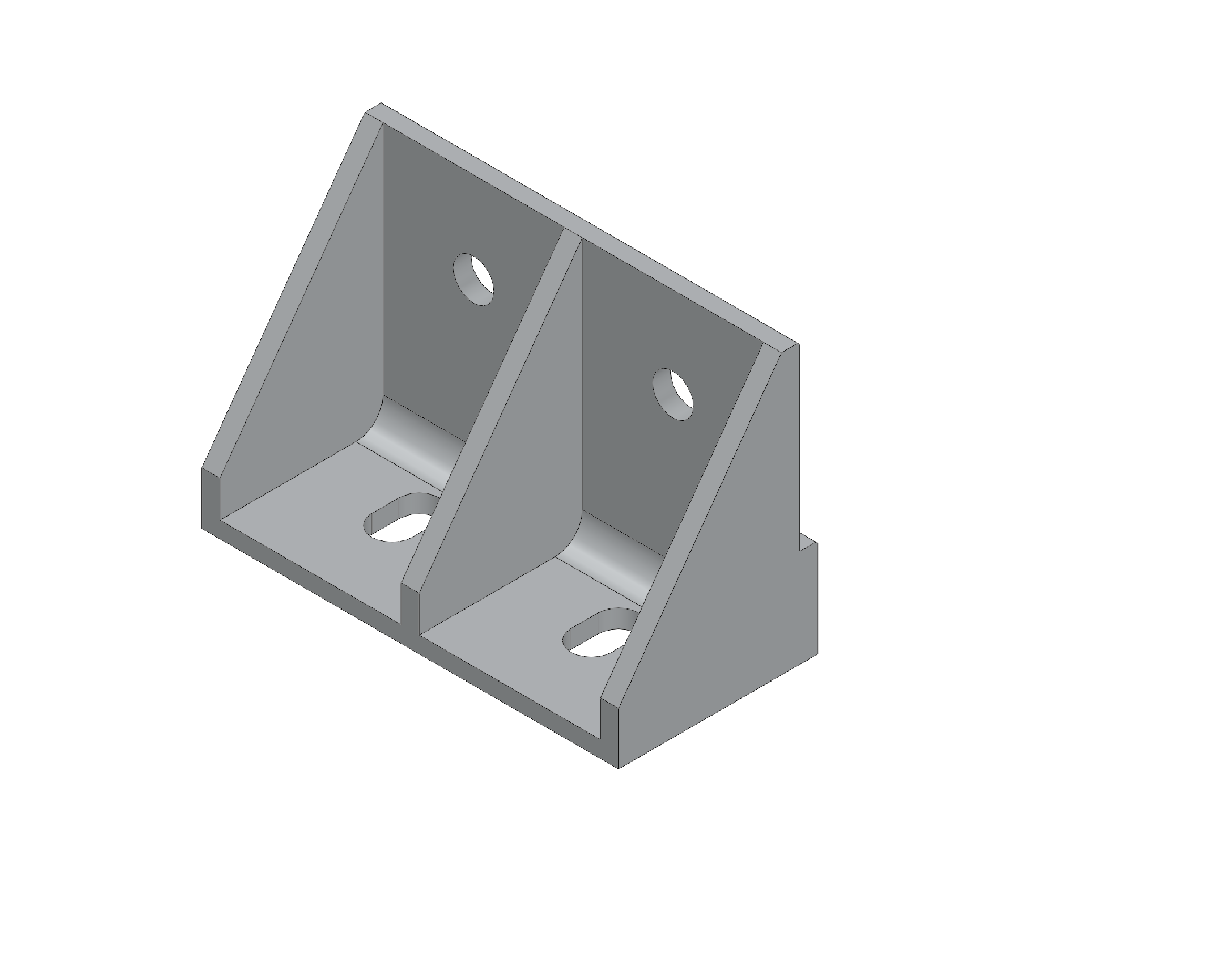
Clamp Double
Similar to the Clamp Single.
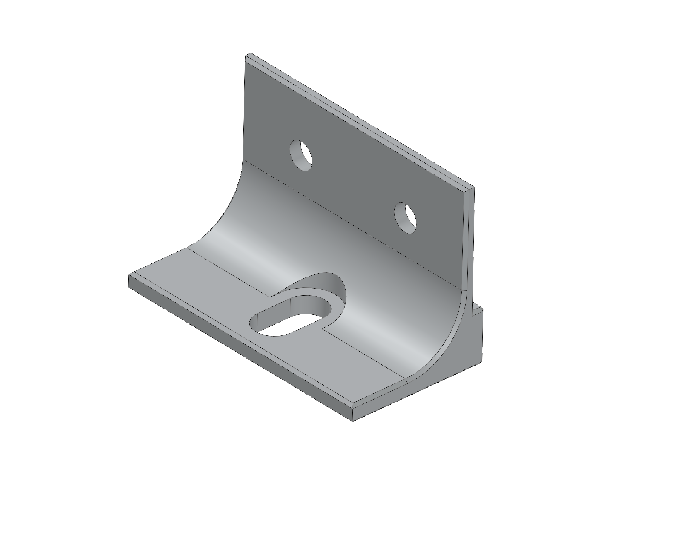
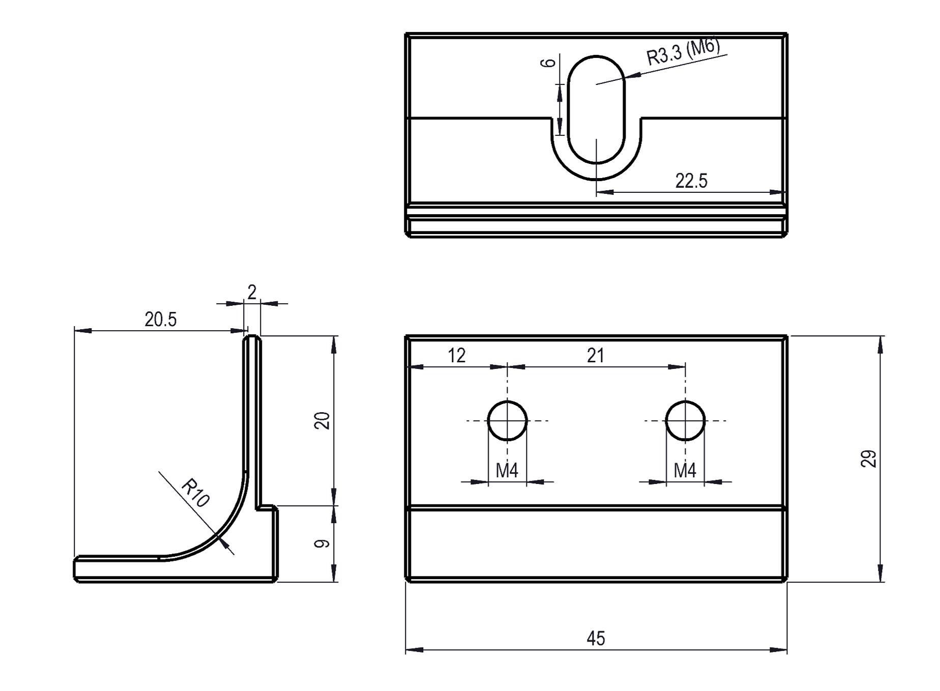
Clamp L
The previous designs are difficult to machine due to the ribs. Additionally, other members of the team suggested removing them as they were aerodynamically inefficient.
It was also suggested to use a bigger screw at the base in order to reduce the number of screws and so the number of assembly operations.
¶ Narrowing the Design Options
¶ Design Criteria
As the requirements are still vague at this stage of the design phase, other criteria are considered:
- Ease of manufacture
- Cost
¶ Trade-off Results
¶ Lay-up
Software: ABAQUS CAE & ABAQUS Standard
Boundary condition: clamped at the root chord
The best lay-up for each core thickness:
| Core [mm] | 1.5 | 2.0 | 3.0 |
|---|---|---|---|
| Lay-up | [0_b[0ₐ,90ₐ,0ₐ,45_b]ₛₒ,C]ₛₒ | [[0ₐ,45_b,0ₐ]₂,C]ₛₒ | [0ₐ,45_b,0ₐ,C]ₛₒ |
| ID | E | G | J |
| Natural Freq. [Hz] |
As expected:
- the first vibratory mode is a flexion mode and the second, a torsion mode
- increasing the thickness increases the natural frequencies.
The first point implies the necessity of "0a" plies, especially close to the surface of the laminate, in order to prevent flexural vibration. Favouring a direction weakens the laminate from other load cases. Nonetheless, adding a-plies oriented differently decreases the natural frequencies if there is a thickness constraint. b-plies are then, the good trade-off (due to bi-directionality) to equilibrate the laminate, improving its flexural strength.
As a matter of fact, the lay-ups are symmetric and balanced in order to avoid any undesired coupling between extension and flexion and, between extension and shear.
¶ Clamps
A fin is cut from a rectangular CFRP sandwich plate
| Advantages | Disadvantages |
|---|---|
| Easy to manufacture | Al clamps |
| Stiffness | |
| Modularity |
¶ Nordend like design
A fin is moulded first using epoxy foam tooling. Second, it is cut into the desired shape. Third, it is glued to a substrate, forming the airfrmae. Then, it is trimmed to the right size. Lastsly it drilled for screws.
https://shop.swiss-composite.ch/pi.php/Formenbau/RAKU-Tool/RAKU-TOOL-WB-0691-PU.html
| Advantages | Disadvantages |
|---|---|
| One unique part | Tooling machining (>9 h per half-mould) |
| Reliable assembly technique | Tooling cost (1072.60.- 1500×500×100 mm) |
| Modularity | Difficult manufacturing procedure |
¶ Detailed Design
A fin is made of CFRP sandwich with aramid honeycomb core and clamped to the Engine-Bay using aluminium clamps. The CFRP part is cut into the desired shape from a sandwich rectangular panel, offering therefore a modularity.
¶ Definitive lay-up
Prepregs
Epoxy based CFRP from Hexcel (HexPly®)
| Denomination | Prepreg | Type | Thickness [mm] |
|---|---|---|---|
| a | EH25/34%/UD136/HTA-12K | UD | 0.14 |
| b | W3T-282-42'-F593-14 | Plain | 0.24 |
Core
- Material: ECA C2-3.2-29 (aramid honeycomb)
- Denomination: C
- [kg.m-3]
- Thickness = [mm]
Geometry (updated during the semester)
- Root chord = [mm]
- Tip chord = [mm]
- Heigth = [mm]
- Sweep length = [mm]
- Sweep angle = [°]
- Targeted thickness = [mm]
Lay-up: [0b,[0a,45b,0a]S,0b,C]SO
Thickness = [mm]
Due to the uncertainties on the load cases, the fin has been thickened. Its lay-up was inspired from the laminate "G", with b-plies at the surface and at the interface with the core. In fact, a woven ply at the surface prevent from peeling damages. A woven ply can adapt more easily to the interface with the honeycomb core compared to a uni-directional ply.
¶ Clamps
- Material: Al 2050 T84
- Yield strength = $$ [MPa]
An arbitrary load case was considered to dimension the screws.
- The fin attachement system shall hold in place the fin in the case where the vehicle with a mass of [kg] is lifted from a fin with an additional .
Load case
- Traction: [kg] [N]
Fin clamping
Two screws and nuts are used per pair of clamp to bolt a fin. the latter is then held by friction. The required clamping force per screw for a friction coefficient between aluminium and carbon epoxy of is then:
M4 screws according to VDI 2230:
| Grade | Force [N] | |
|---|---|---|
| 8.8 | 2500 | 1.04 |
| 10.9 | 4000 | 1.67 |
| 12.9 | 6300 | 2.63 |
M4 screws grade 8.8 are sufficient to clamp the fins.
Assembly to a rod
One screw is used per clamp to bolt a fin on a rod. The required pre-charge per screw is then:
M6 screws accordingto VDI 2230:
| Grade | Force [N] | FoS |
|---|---|---|
| 8.8 | 6300 | 11.45 |
| 10.9 | 10000 | 18.18 |
| 12.9 | 16000 | 29.09 |
M6 screws grade 8.8 are largely sufficient to bolt a clamp on a road. As a matter of fact, M4 screws grade 8.8 offer a .
¶ Leading and trailing edges
The leading and trailing edges are often sharp in order to reduce the drag. In the previous years, this was achieved by just sanding the CFRP fin. However, with the current design, the honeycomb core cannot be sanded. Some research work were already done on the thermal protection for a spaceshot rocket's fins (NOAH) and it provides indication on how to protect the edges. A protection system composed of two parts was proposed: a titanium shell (i.e. metallic shell) glued using of Resbond™ 940LE paste (silica based ceramic adhesive). Using a similar system can mitigate the issue with sandwich fin while providing a thermal protection.
¶ FEA
 2024_C_ST_FINS_FEA
¶ Perspectives
- Clamping system
Additional FEA will will be needed to refine the clamping system design once the FD division has given CFD data. - Leading and trailing edges
Same problematic as for the nosecone, these edges shall resist to thermal load. Again, CFD data are needed. Moreover, some reseaech needs to be done on the manufacturing of the provided solution. - Testing plan
Vibratory tests with the clamping boundary condition can be performed to measure the natural frequencies, qualifying therefore the structural integrity.
¶ Relevant Documents
- 2024_C_SE_REQ_01 LV declaration of purpose
The LV shall be a mean of testing spaceshot technologies and participate in the L9 flight category at the 2025 EuRoC competition ([9000]m apogee).
- 2024_C_SE_REQ_01 LV declaration of purpose
The LV shall be a mean of testing spaceshot technologies and participate in the L9 flight category at the 2025 EuRoC competition ([9000]m apogee).
- 2024_C_SE_REQ_01 LV declaration of purpose
The LV shall be a mean of testing spaceshot technologies and participate in the L9 flight category at the 2025 EuRoC competition ([9000]m apogee).
- 2024_C_SE_REQ_01 LV declaration of purpose
The LV shall be a mean of testing spaceshot technologies and participate in the L9 flight category at the 2025 EuRoC competition ([9000]m apogee).
- 2024_C_SE_REQ_01 LV declaration of purpose
The LV shall be a mean of testing spaceshot technologies and participate in the L9 flight category at the 2025 EuRoC competition ([9000]m apogee).