¶ Introduction
¶ Purpose, Objective and Scope
This document aims to describe the detailed manufacturing procedure of the sandwich pannel of FIREHORN's fins.
It is addressed to the team members of C-ST and serves as a reference for the future CFRP fins.
The document will only cover the laminating part of the procedure. It will not describe the cutting of the fins.
Legends for highlighted text:
Function
Warning / Things to be careful of
Risks
Tips and Indications
Methods
- C: Competition
- CFRP: Carbon Fibres Reinforced Polymers
- MS: Makerspace
- Prepreg: Pre-impregnated fibres
- ST: Structure team
- UD: Uni-directional
¶ Applicable and Reference Documents
- 2024_C_ST_FINS_DJF
- UD: HexPly® EH25
- Woven: HexPly® F593
- Adhesive: HexBond® 312L
- HoneyComb: ECA C2-3.2-29
¶ Curing Cycle Report
¶ Parts List
| Description | Part Ref | Qty |
|---|---|---|
| Sandwich pannel | TX | 1 |
¶ Pre-Operations Checklist
¶ Participants
Number:
¶ On-site
| Check | Responsible for: | Name |
|---|---|---|
| COO | (x1) | |
| Cutter prepregs | (x2) | |
| Cutter consumables | (x1) | |
| Compactage/drappage | (x4) |
¶ Raw Material
¶ Makerspace / DLL
| Check | Item | Qty |
|---|---|---|
| Bubble wrap (OBI) | \ | |
| HoneyComb | 1250x1250 [mm] |
¶ APCO
| Check | Item | Qty |
|---|---|---|
| HexPly®EH25/34 %/UD136/HTA-12K | \ | |
| HexPly® W3T-282-42'-F593-14 | \ | |
| Adhesive | \ | |
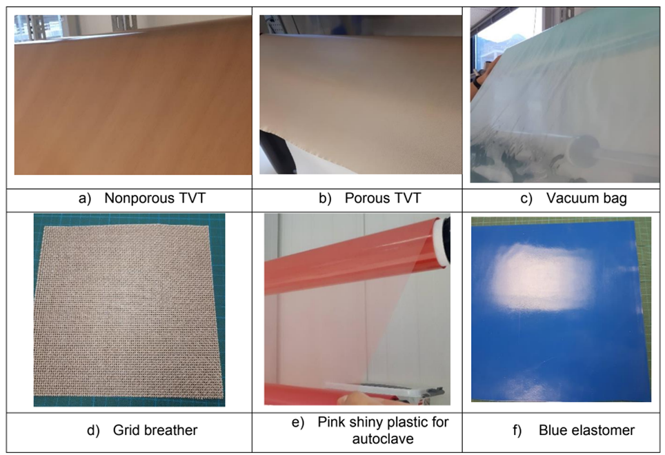
| Substrate (~table) | \ | |
| Porous TVT / Peel-ply | \ | |
| Non-porous TVT | \ | |
| Non-perforated film release | \ | |
| Breather | \ | |
| Grid breather | \ | |
| Vacuum bag | \ | |
| Elastomer | \ |
¶ Tools
¶ Storage Location
| Check | Item | Tool Ref | Qty | Image |
|---|---|---|---|---|
¶ APCO
| Check | Item | Tool Ref | Qty | Image |
|---|---|---|---|---|
| Safety goggles | ||||
| Nitrile gloves | ||||
| Measuring tools | ||||
| Weights | ||||
| Cutting tools | ||||
| Spiker | ||||
| Freeze spray | ||||
| PTFE tape | ||||
| Tacky tape | ||||
| Vacuuming connectors | ||||
| Manometer | ||||
| Autoclave |
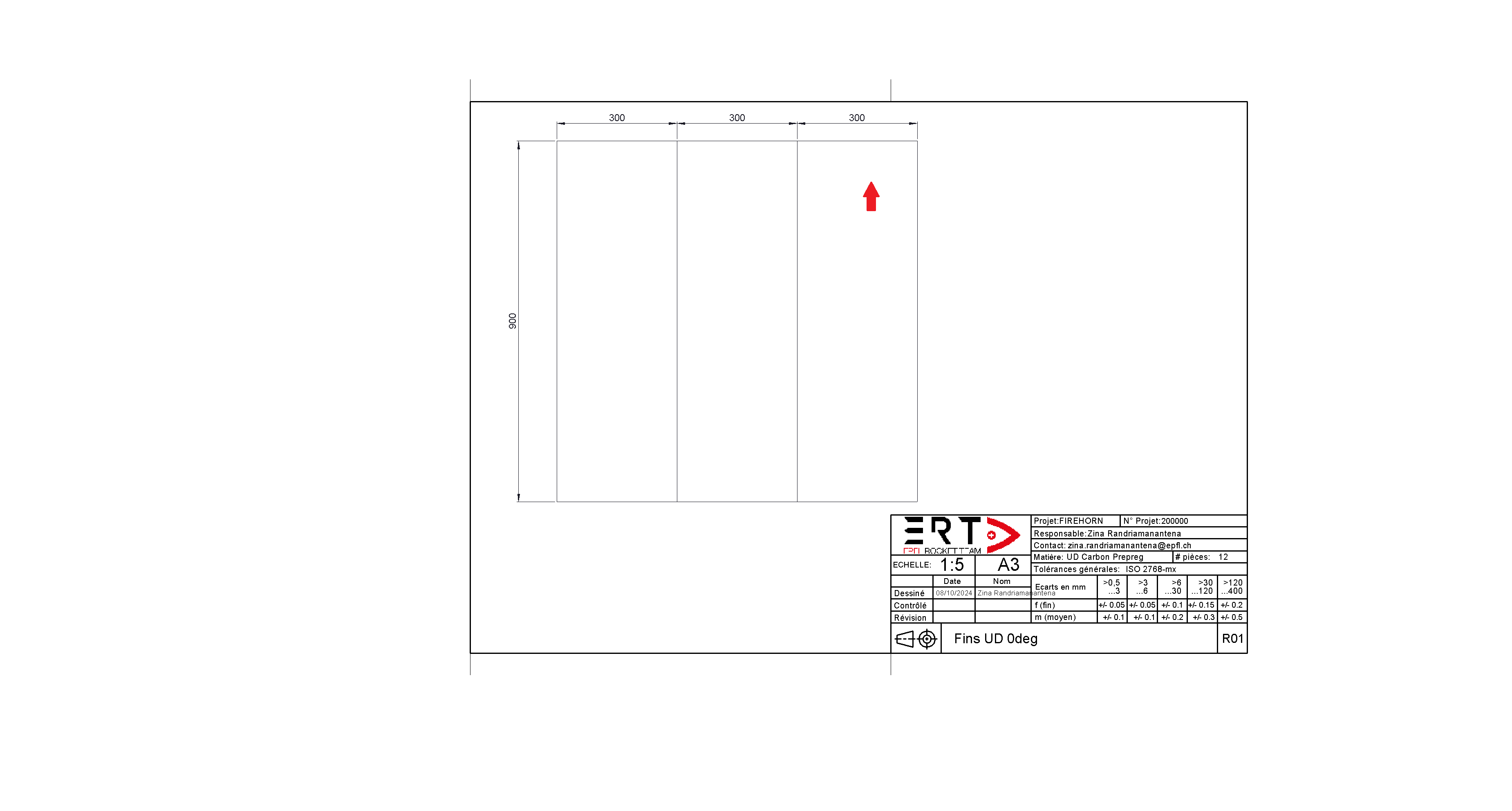
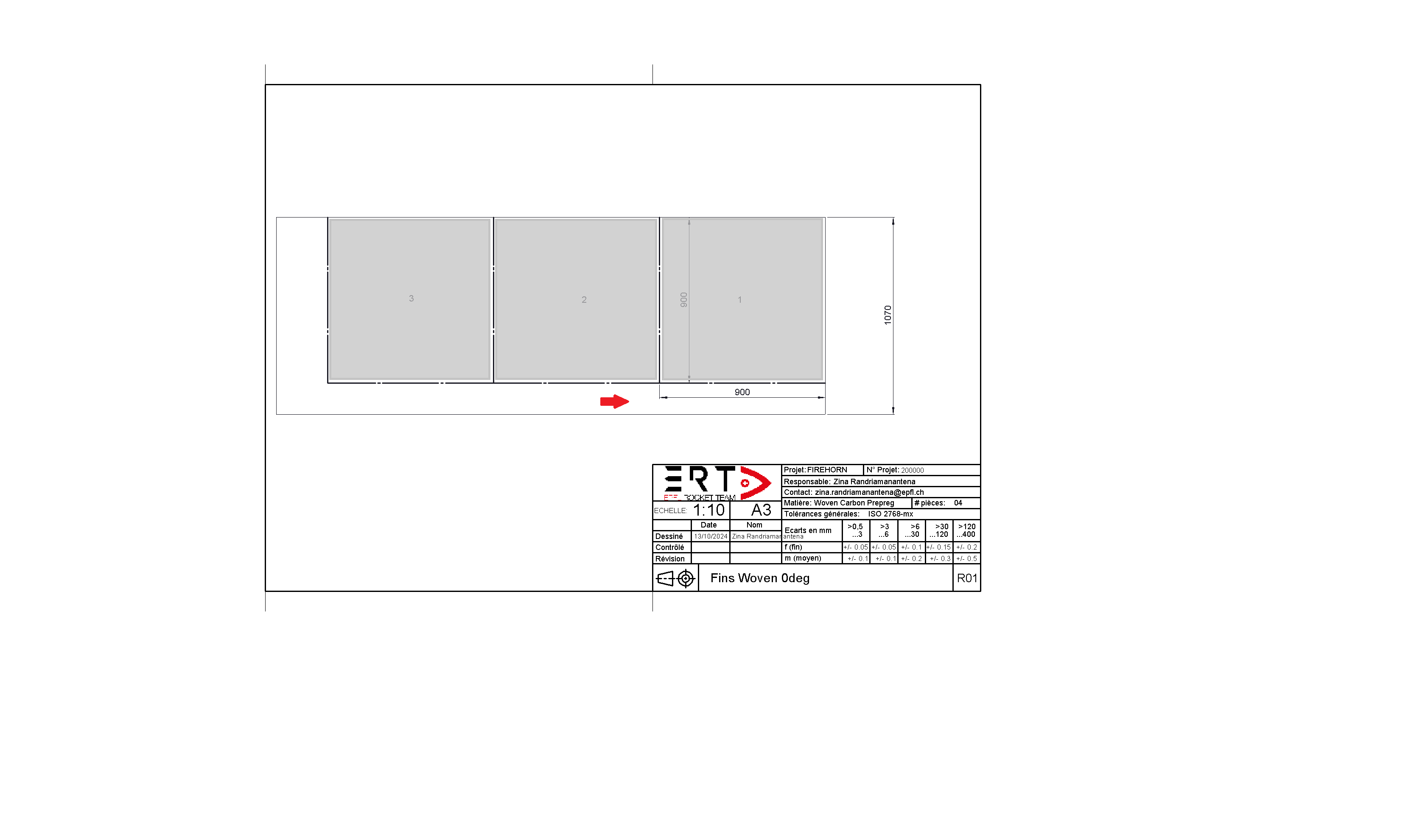
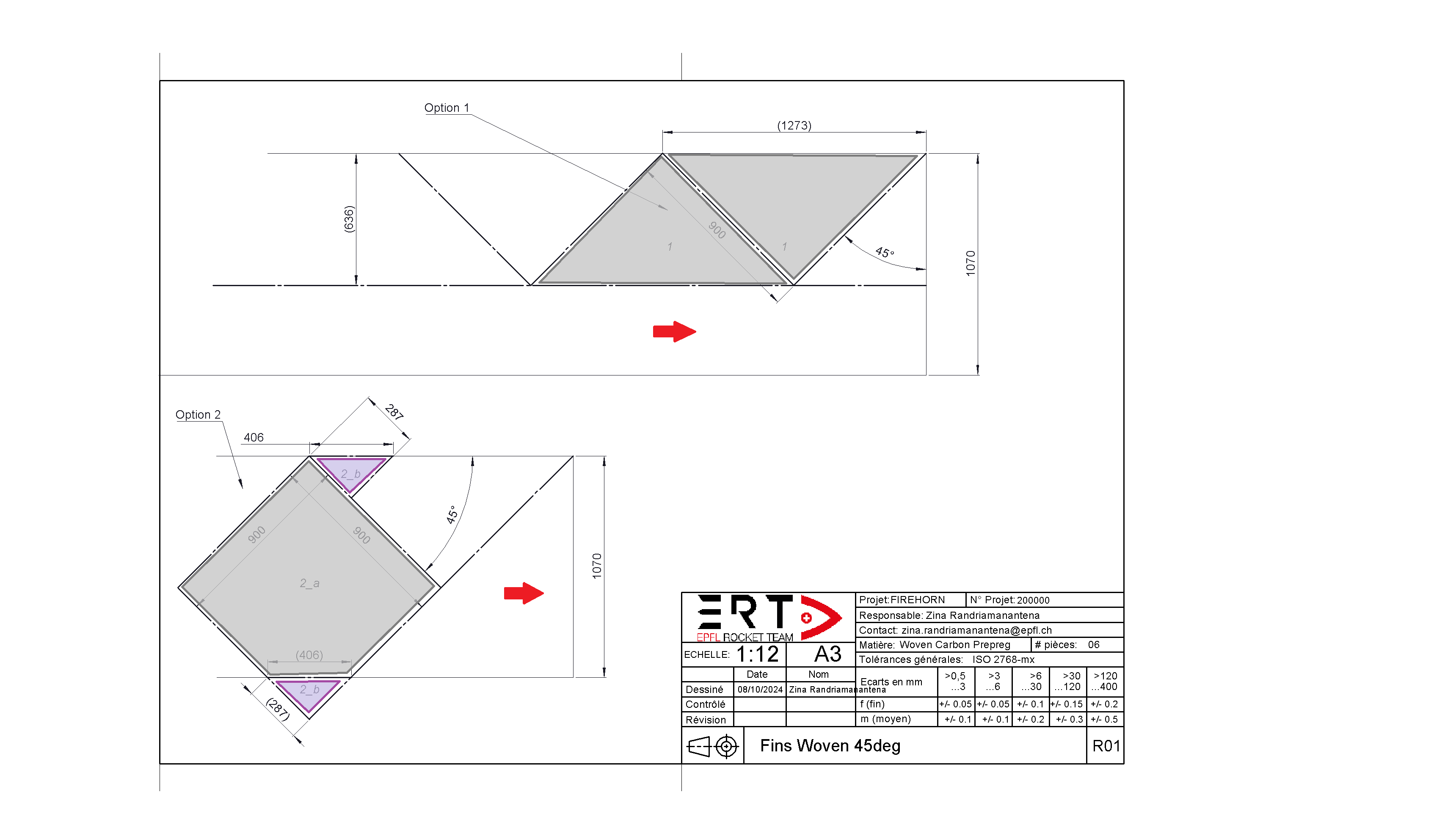
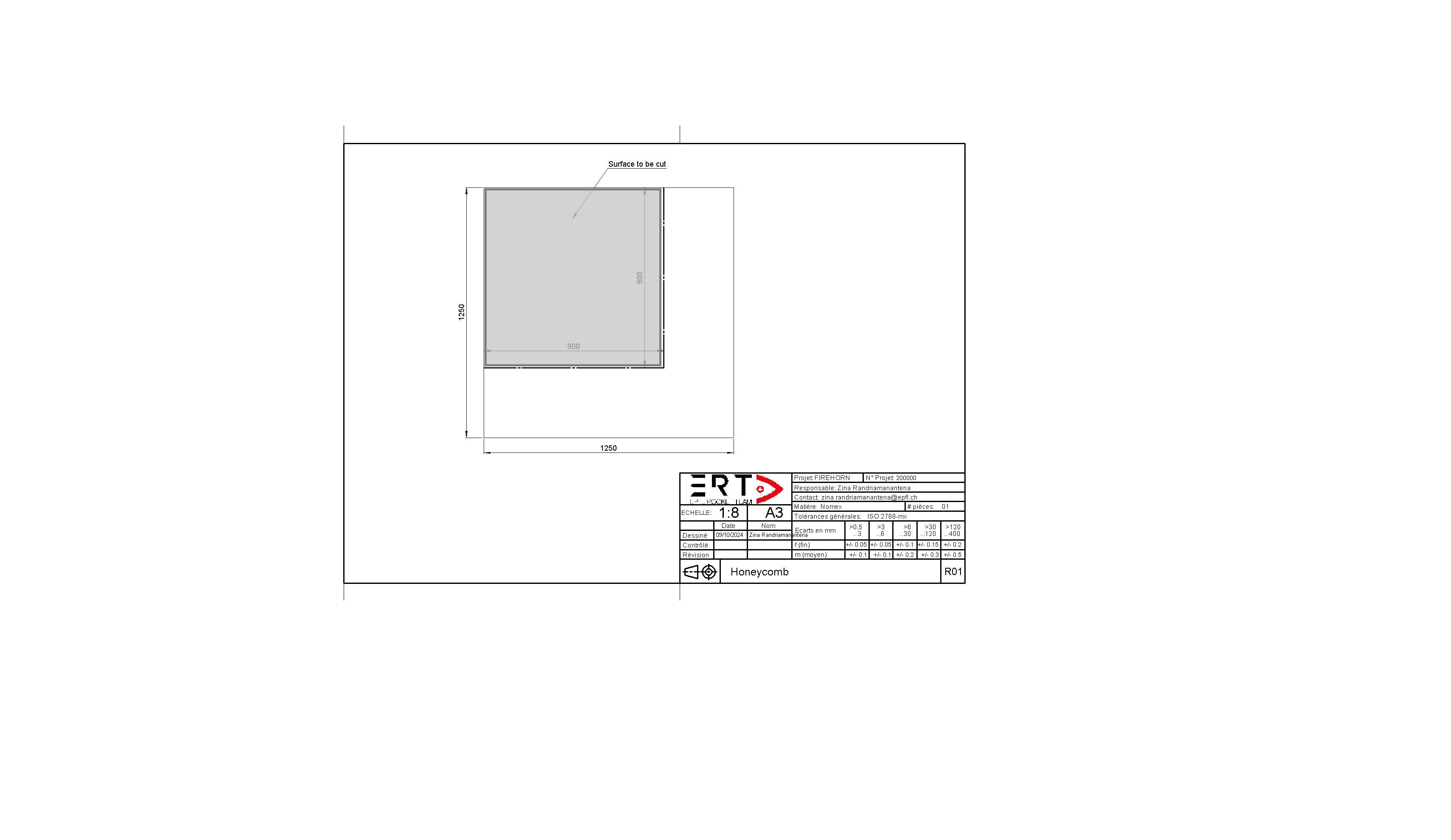
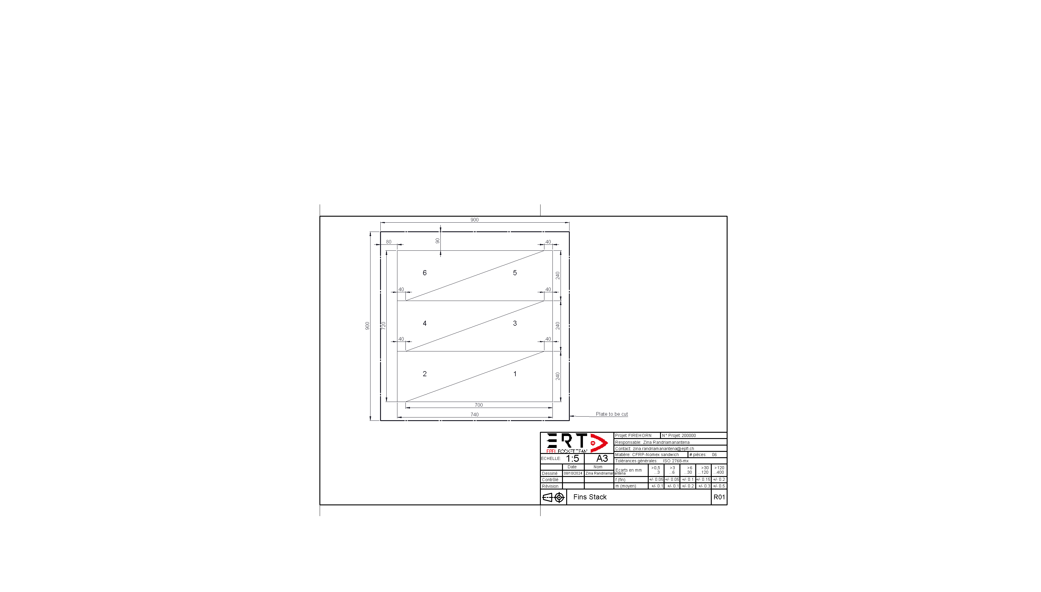
¶ Technical drawings
- Solid lines indicate the prepreg roll
- Dashed lines are the cutting lines
- Couloured areas indicate the desired cut
- Red arrow indicates the orientation of the roll's fibres
Be careful not to make the mistake of producing square plates as in 2024. This increases the risk of misaligning the fibers when assembling the sheets with honeycomb.
¶ Workflow
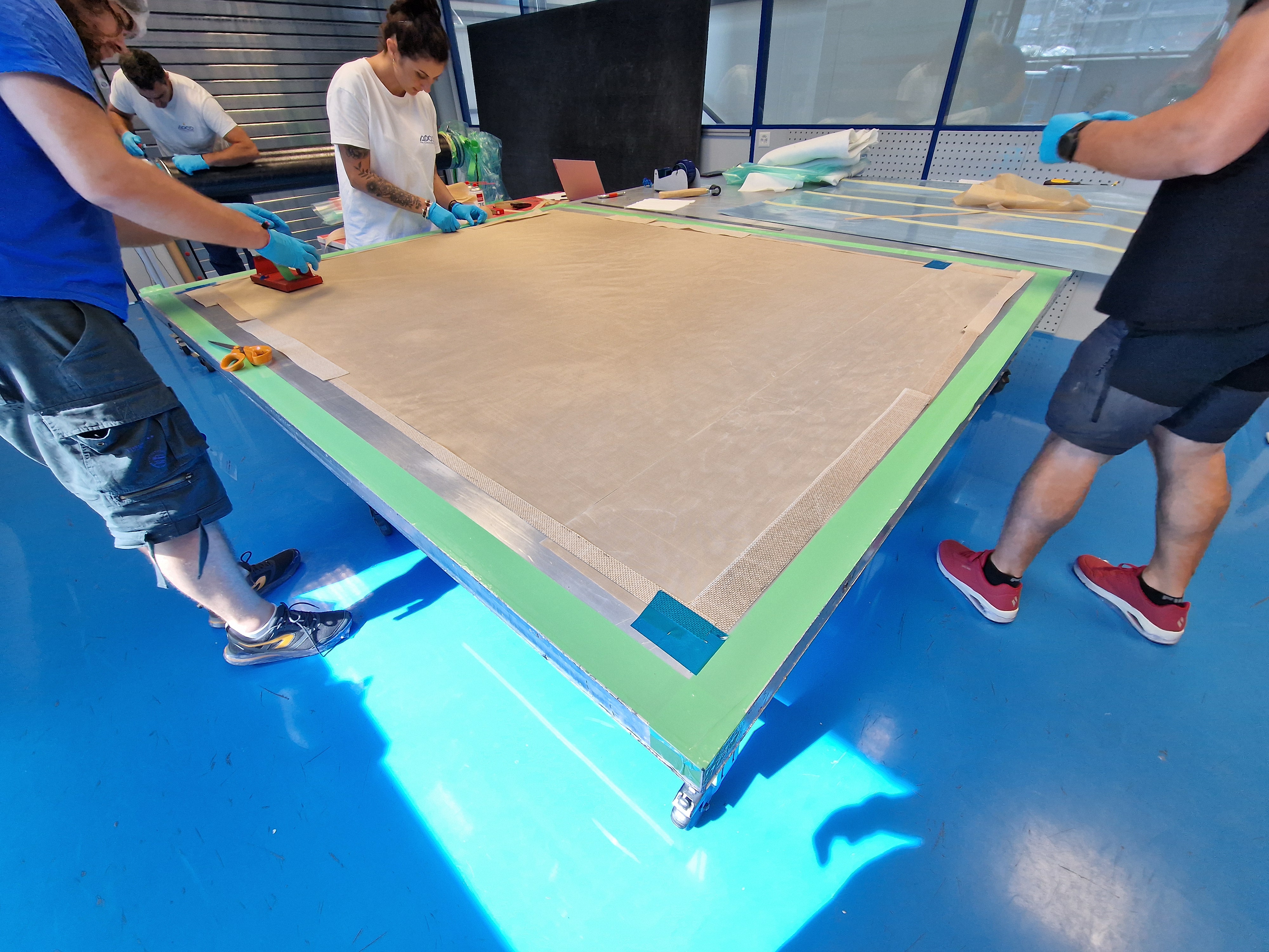
¶ Substrate preparation
- Cut porous TVT of slighly bigger than the desired plate (i.e. leave >20cm of margin on each side).
- Dimensions ~ 1100 [mm] x 1100 [mm]
- Clean the substrate with alcohol.
- Apply porous TVT on the substrate.
- Tape the TVT with PTFE tape.
Make sure that the TVT is well tensioned
- Tape one side of the substrate with scotch "carrossier".
- Draw a rosette on the tape with clear indication of axis.
These are references for the lay-up application
¶ Prepregs cutting
The cutting patterns are given as a technical drawing
¶ 1. Raw cut 0°
- Cut 900 [mm] (x3) from the UD roll.
- Tape together (no need for the whole length) the strips using carrossier tape.
- Write the number of the obtained ply.
¶ 2. Raw cut 45°
- Draw lines at +45° and -45° (alternatively) from the main axis of the roll.
- Cut half squares of 900mm sides with the main axis of the roll as diagonals
- Tape halves together with the smallest possible gap.
- Write the number of the obtained ply.
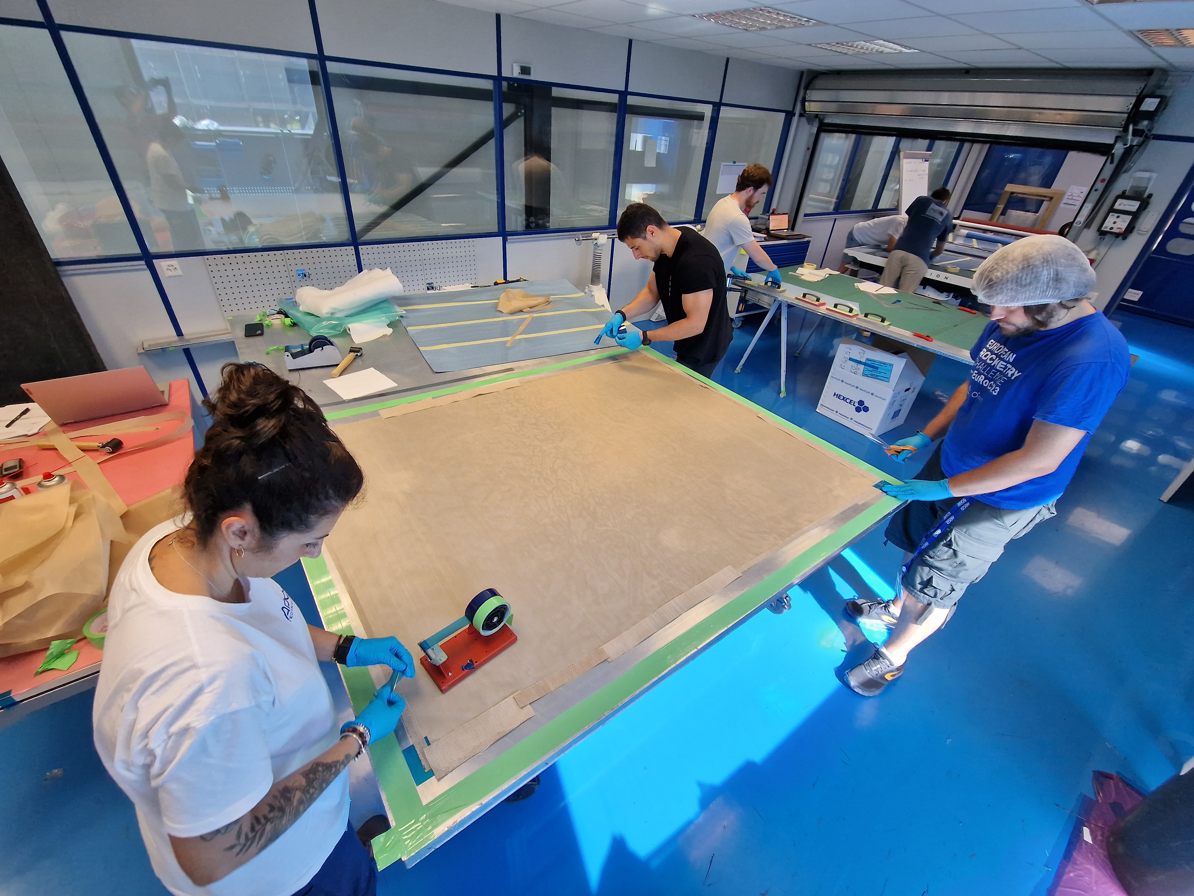
¶ Lay-up
- The operator must sign each time a ply is layed-up
- The COO have to verify that intermediate vacuuming has been done before allowing the application of next ply
Do not forget to remove patchworking tape
Place a piece of paper next to the plate on which is written the layer number, the fiber orientation and the intermediate vacuum. Be flexible when it comes to intermediate vacuum. If the layer has not been perfectly draped and you have a few bubbles, or if the layer does not adhere well to the underlay, make an intermediate vacuum even if it is not written on the control sheet.
¶ Skin 1
| n° | Type | Orientation [°] | Operator | Check |
|---|---|---|---|---|
| 1 | Woven | 0 | ||
| Vaccum | 10 [min] | |||
| 2 | UD | 0 | ||
| 3 | Woven | 45 | ||
| Vaccum | 10 [min] | |||
| 4 | UD | 0 | ||
| 5 | UD | 0 | ||
| 6 | Woven | -45 | ||
| Vaccum | 10 [min] | |||
| 7 | UD | 0 | ||
| 8 | UD | 0 | ||
| 9 | Woven | 45 | ||
| Vaccum | 10 [min] | |||
| 10 | UD | 0 | ||
| 11 | Woven | 0 | ||
| Vaccum | 10 [min] |
¶ Skin 2
| n° | Type | Orientation [°] | Operator | Check |
|---|---|---|---|---|
| 1 | Woven | 0 | ||
| Vaccum | 10 [min] | |||
| 2 | UD | 0 | ||
| 3 | Woven | 45 | ||
| Vaccum | 10 [min] | |||
| 4 | UD | 0 | ||
| 5 | UD | 0 | ||
| 6 | Woven | -45 | ||
| Vaccum | 10 [min] | |||
| 7 | UD | 0 | ||
| 8 | UD | 0 | ||
| 9 | Woven | 45 | ||
| Vaccum | 10 [min] | |||
| 10 | UD | 0 | ||
| 11 | Woven | 0 | ||
| Vaccum | 10 [min] |
¶ How to apply prepreg ?
¶ Reference corner definition
Because the layups don't have the exact same dimensions, it can be hard to place them accurately on top of eachother. Define a corner from which you will start all layups to increase the precision of the process.
¶ 0° prepreg
- Apply the ply directly on the substrate, starting from the reference corner.
¶ 45° prepreg
- Apply the ply directly on the substrate, starting from the reference corner.
If you have overlaps, do not stack all the overlaps on the same side
Localised overlaps stacking is a point of failure
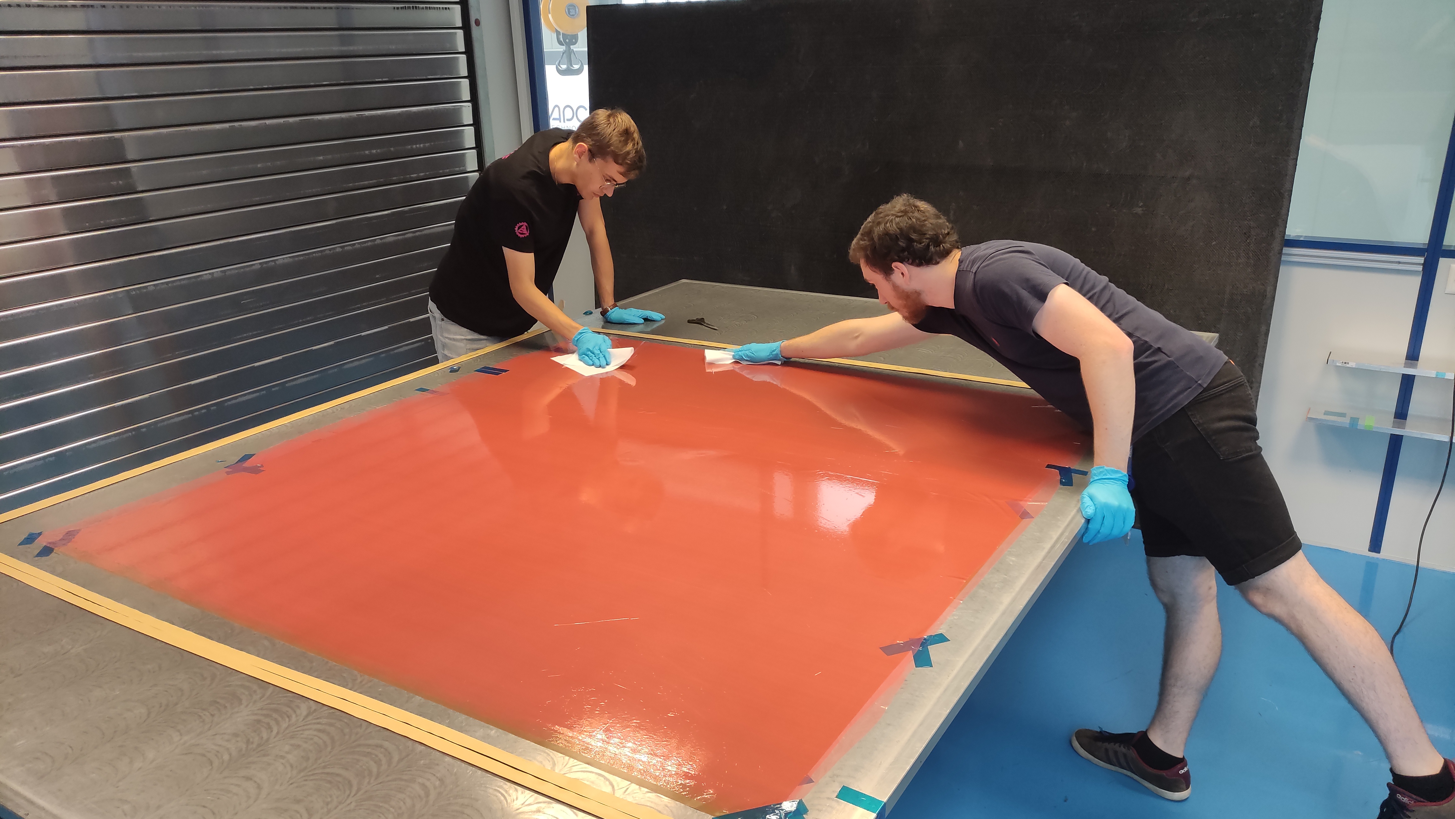
¶ How to Intermediate vacuum ?
To compact properly the ply against the substrate
- Apply non-porous TVT on the top of the laminate.
- Put grid breather around the plate and secure it with tape
- Put a vacuuming disc on top of the grid breather strip.
- Cover the stacking with a vacuum bag.
- Seal the vacuum bag against the substrate.
The vacuum bag is bigger than the laminate and this is normal. Ask for help to fit this bag with the laminate using "ears" technique.
Ears allow the 2D bag to adapt to the 3D laminate
- Screw the "teton" to the vacuuming disc.
- Vacuum.
Look for help when using the "teton"
Mishandling of the "teton" can pierce the vacuum bag.
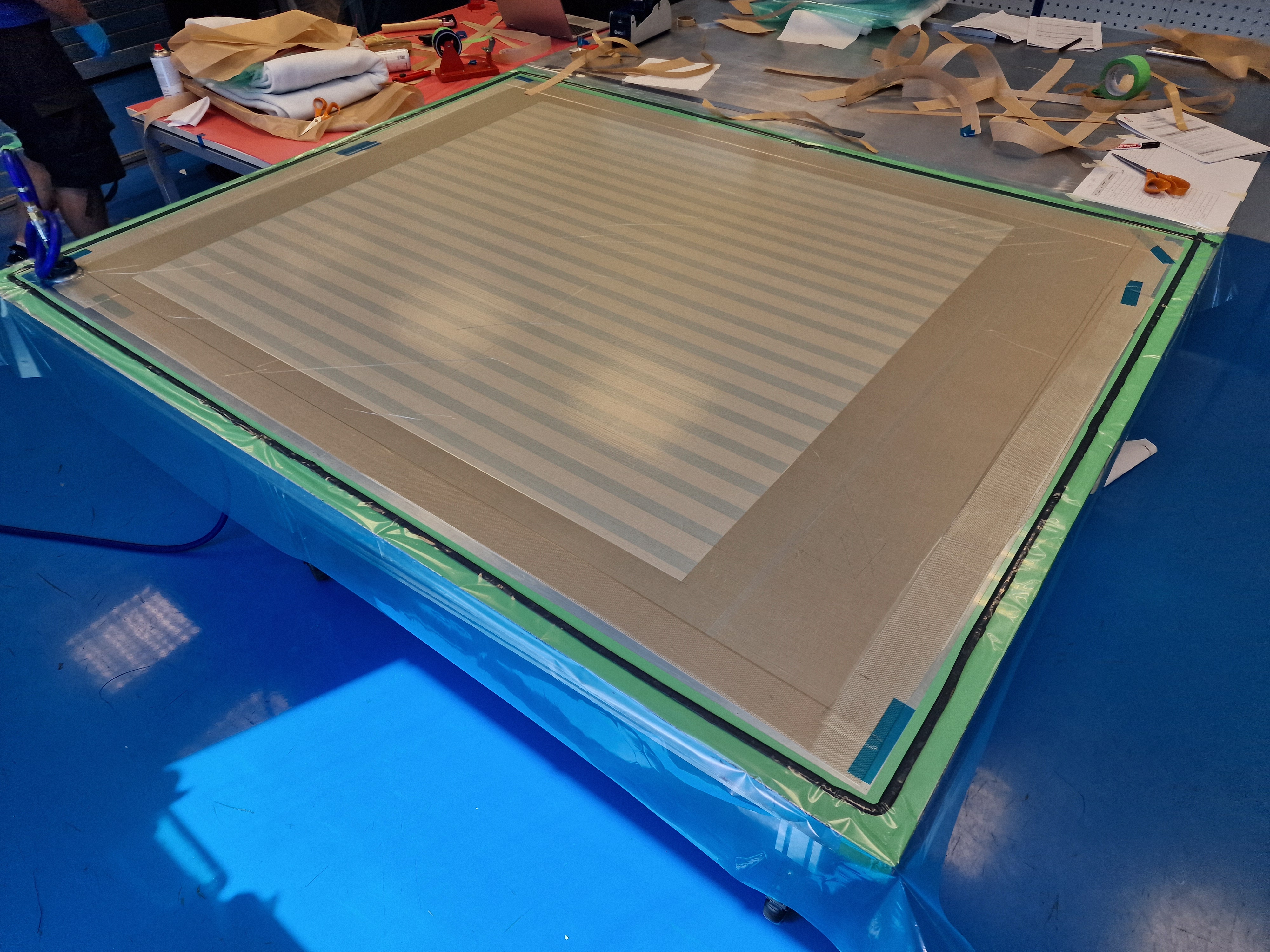
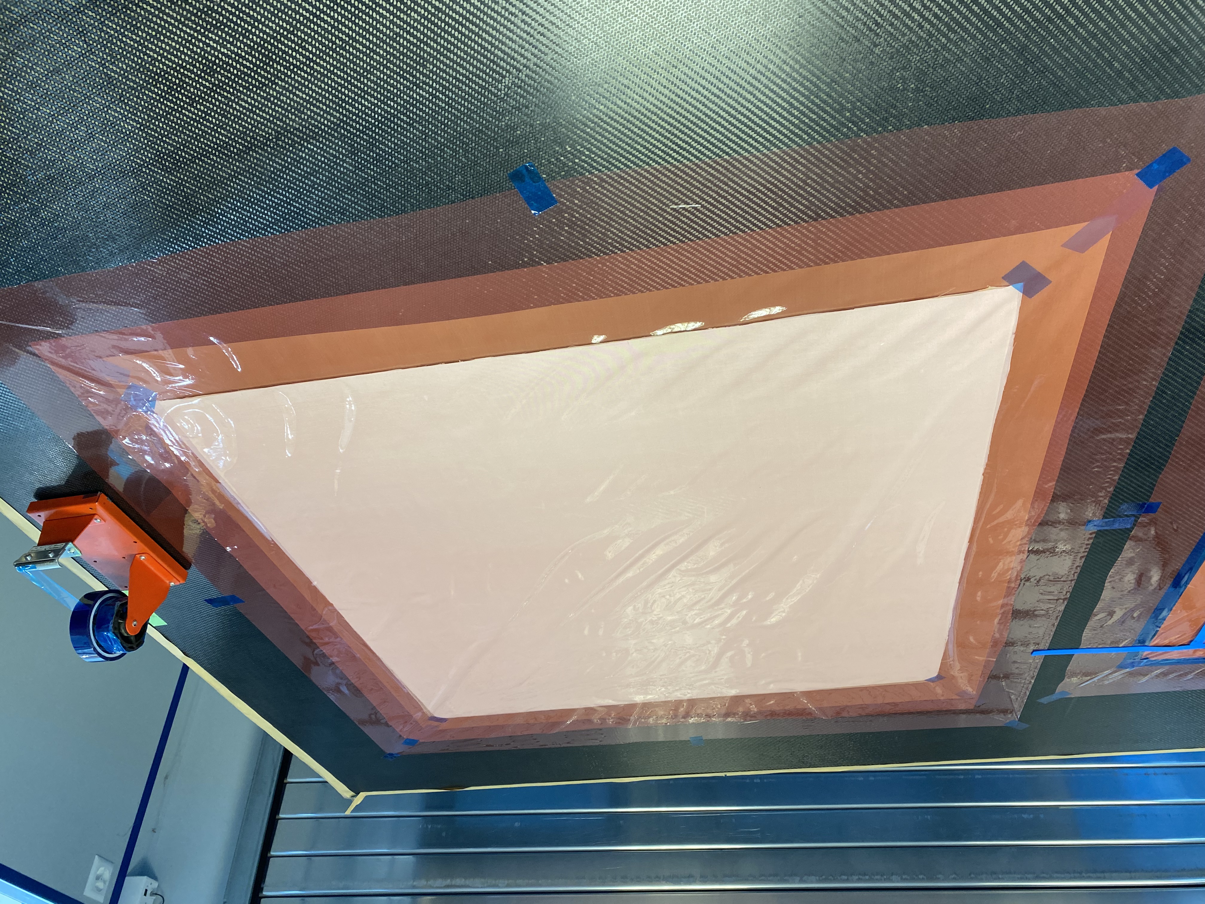
¶ Final vacuum
- Apply 1 layer of Non-Porous TVT larger than the plate (add 10cm on each side) on the subtrate.
- Apply 1 layer of A5000 larger than the plate (add 20cm on each side).
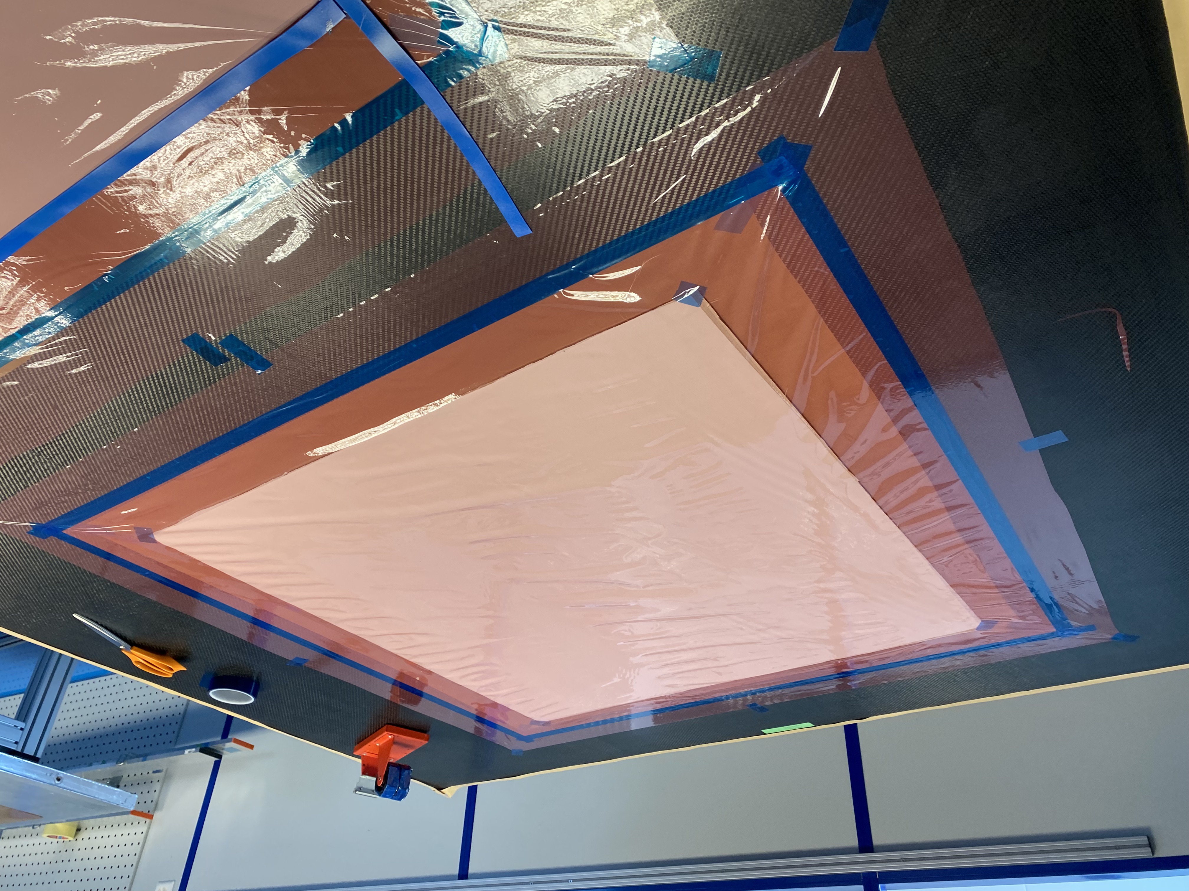
A good way to apply this layer is to do a kind of Swiss cross with the PTFE tape by putting 4 of them on the centers of the sides of the layer. Do that while keeping the layer under slight tension (not too much) in order to not fold and not let air bubble under it. Then do the same for the corners of the layer.
If you need two strips to make one layer, align the joint in the same direction as the 0° fiber and place it in a location where carbon will not be used. Create a 1 mm overlap, and avoid placing the joints of every layer in the same position.
- Apply the carbon plate
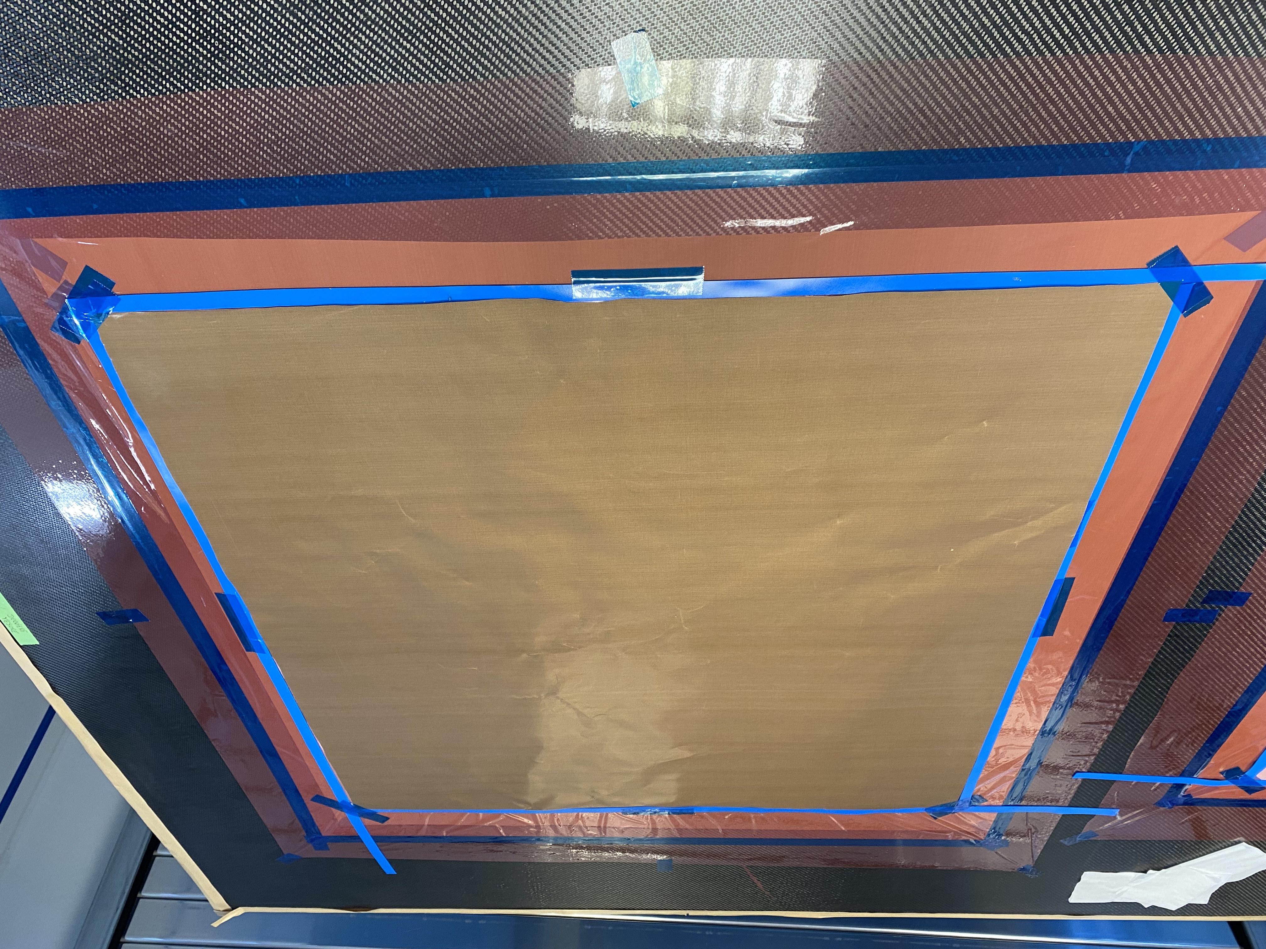
- Apply a layer of Porous TVT the same size as the plate
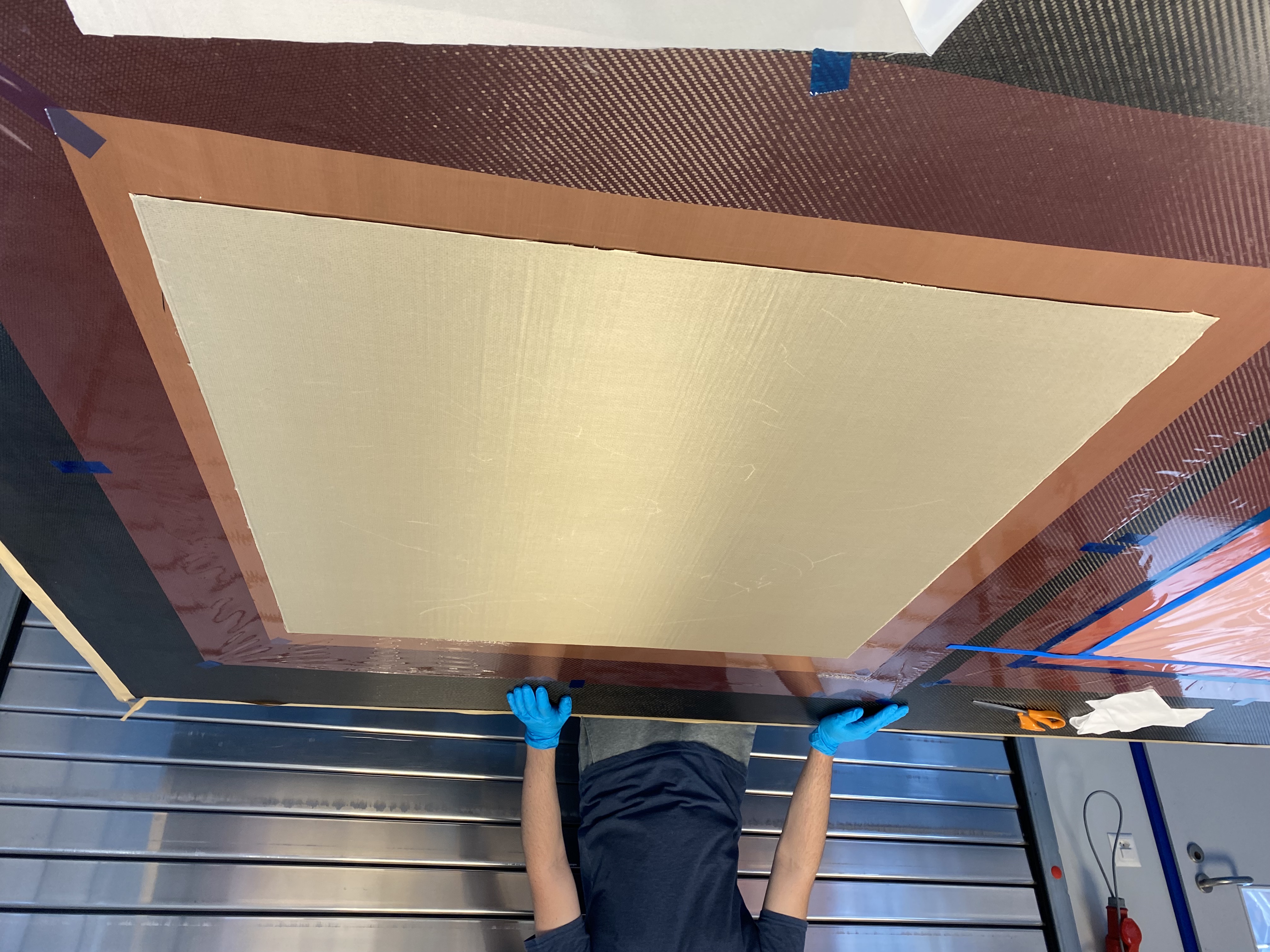
- Apply a layer of 'white' the same size as the plate
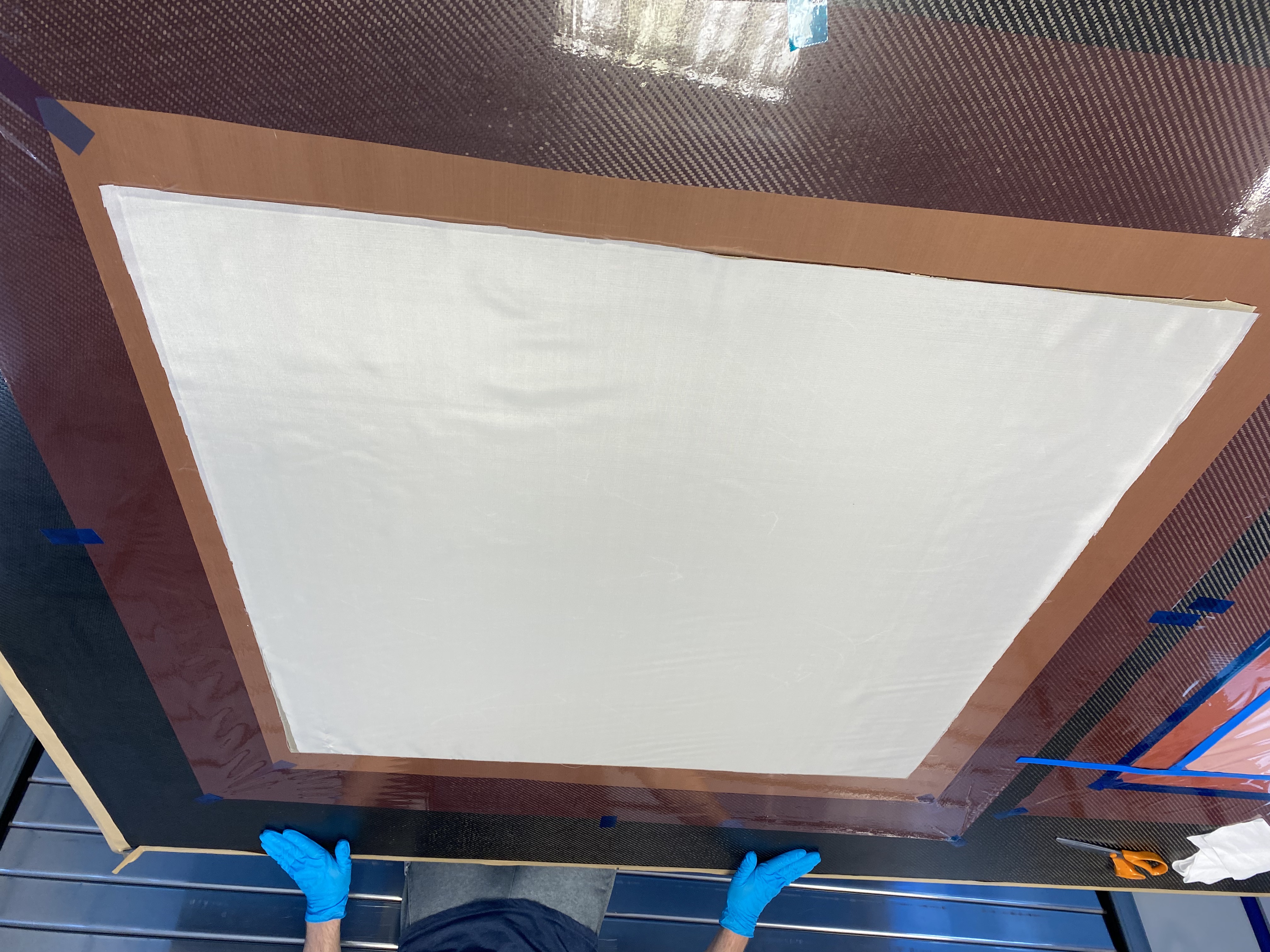
- Apply 1 layer of A5000 larger than the plate but smaller than the previous A5000 layer (add 10cm on each side).
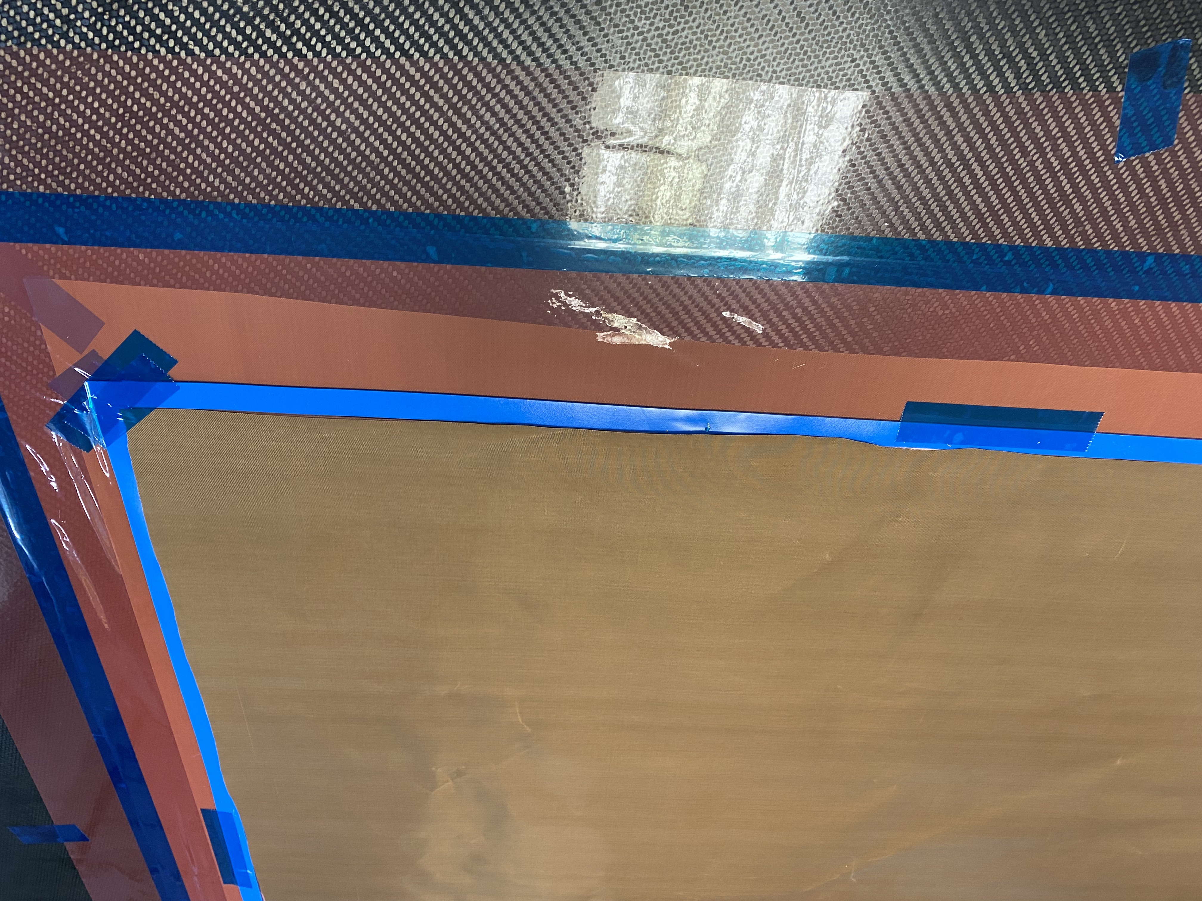
- Use PTFE tape to connect the two A5000 layers together (apply tape on the entire length to make the connection leak-proof).
- Apply a layer of Non-Porous TVT the same size as the plate.
- Apply strips of Amosite tape along the edges of the carbon plate (no overlap with Non-Porous TVT).
- Apply a layer of Breather on the entire marbre.
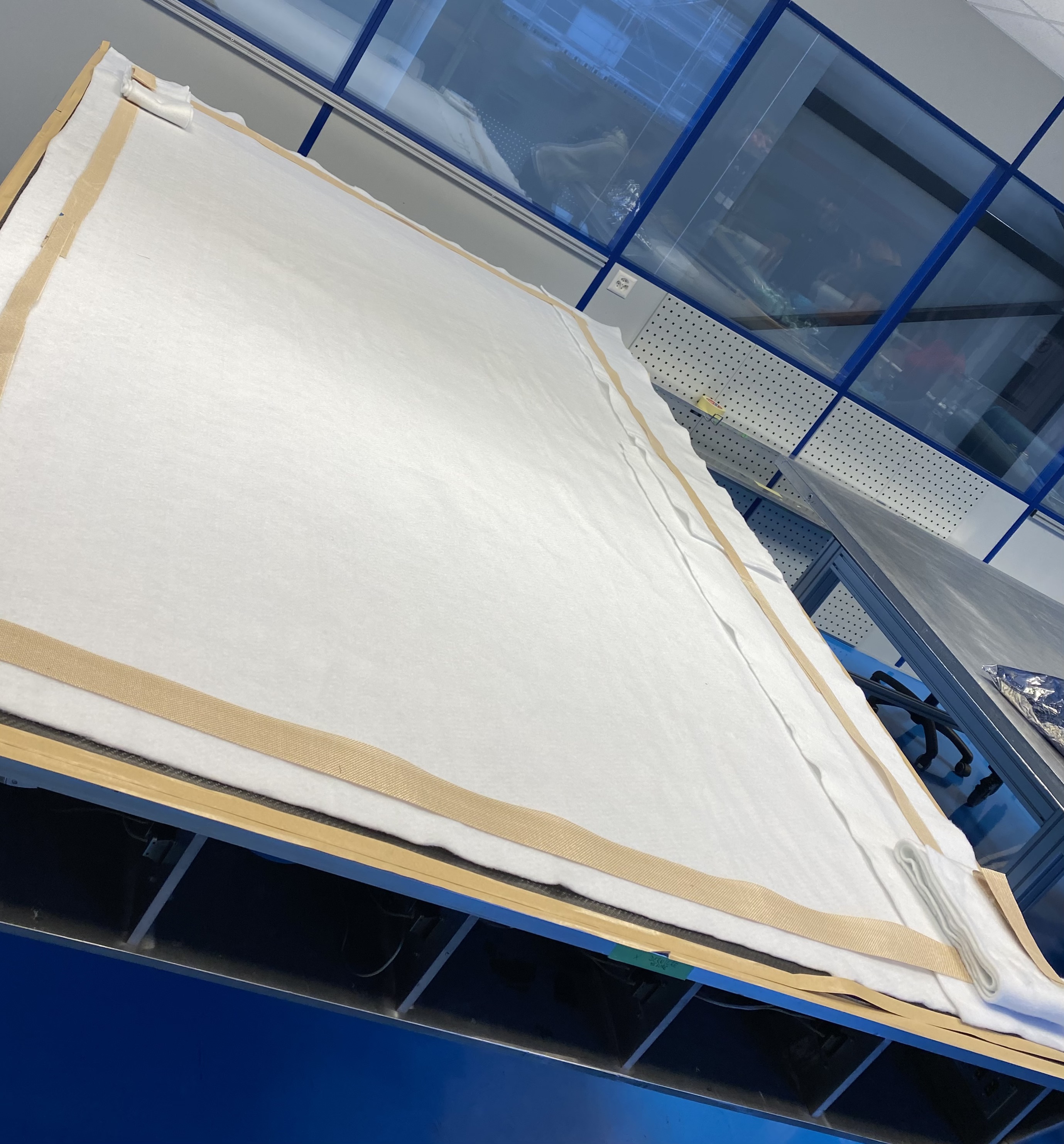
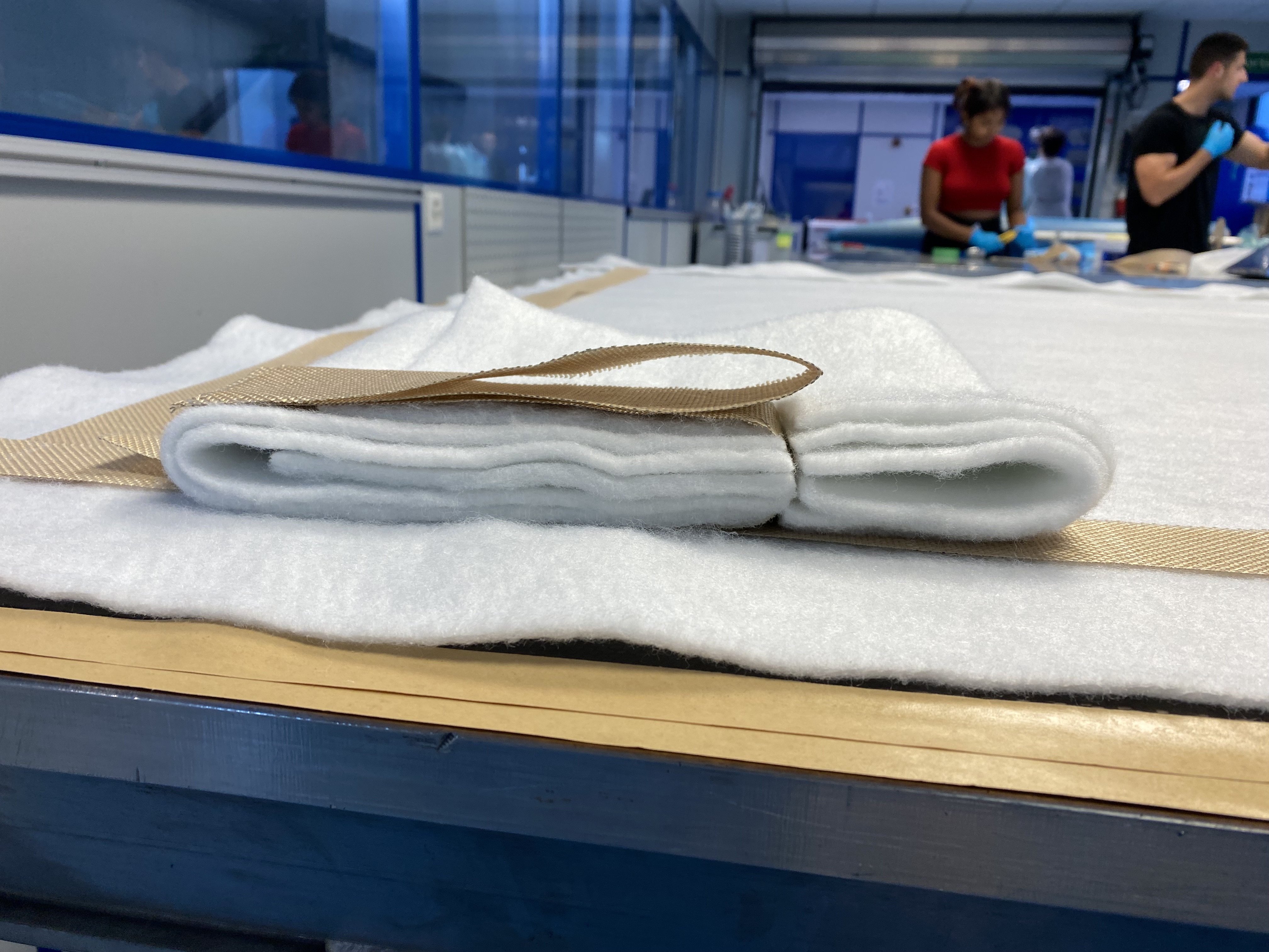
- Cut a ~20cm wide and ~100cm long strip of breather and fold it 5 times to make at least 6 layers.
- Add 1 layer of grid breather on the breather and secure the vaccum discs to the staking with PTFE blue tape.
- Apply the vaccum bag larger than the plate (add 40cm on each side and make ears).
- Seal the ears.
- Apply vacuum and plug any leak.
Vacuum need to be maintained successfully (without any leak) for 20' before it can be transferred to the autoclave. (To make sure that the vacuum bag will not burst in the autoclave)
¶ Curing cycle 1
- Time: 350 [min] 5 [h] 50 [min]
- Heat the part to 60 [°C] with a speed of 2 [°C.min−1]
- Keep it at 60 [°C] for 30 [min] while applying 5 [bar] of pressure
- Heat the part to 180 [°C] with speed of 2 [°C.min−1]
- Keep it at 180 [°C] for 150 [min]
- Cool the part to 20 [°C] with speed of 2 [°C.min−1]
- Depressurise the autoclave
¶ HoneyComb
- Cut two 900x900 [mm] squares of adhesive film
- Remove peel-ply from skins
- Lay the adhesive films on to skin 1 & 2
- Peel off the polythene interleave of skin 1
- Apply the honeycomb to the exposed adhesive surface of skin 1
- Peel off the polythene interleave of skin 2
- Apply the exposed adhesive surface of skin 2 to the honeycomb
- Final vacuum process
¶ Curing cycle 2
- Time: 104 [min] 1 [h] 44[min]
- Heat the part to 60 [°C] with a speed of 5 [°C.min−1]
- Keep it at 60 [°C] for 30 [min] while applying 3 [bar] of pressure
- Heat the part to 120 [°C] with speed of 5 [°C.min−1]
- Keep it at 120 [°C] for 30 [min]
- Cool the part to 20 [°C] with speed of 5 [°C.min−1]
- Depressurise the autoclave
¶ Post Conditions
| Check | Step | Description | Image |
|---|---|---|---|
| 1 | Check for wrinklings | ||
| 2 | Check for cracks | ||
| 3 | Check the surfaces | ||
| 4 | Do some dimension checks |