¶ Introduction
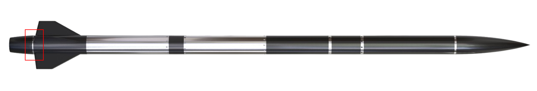
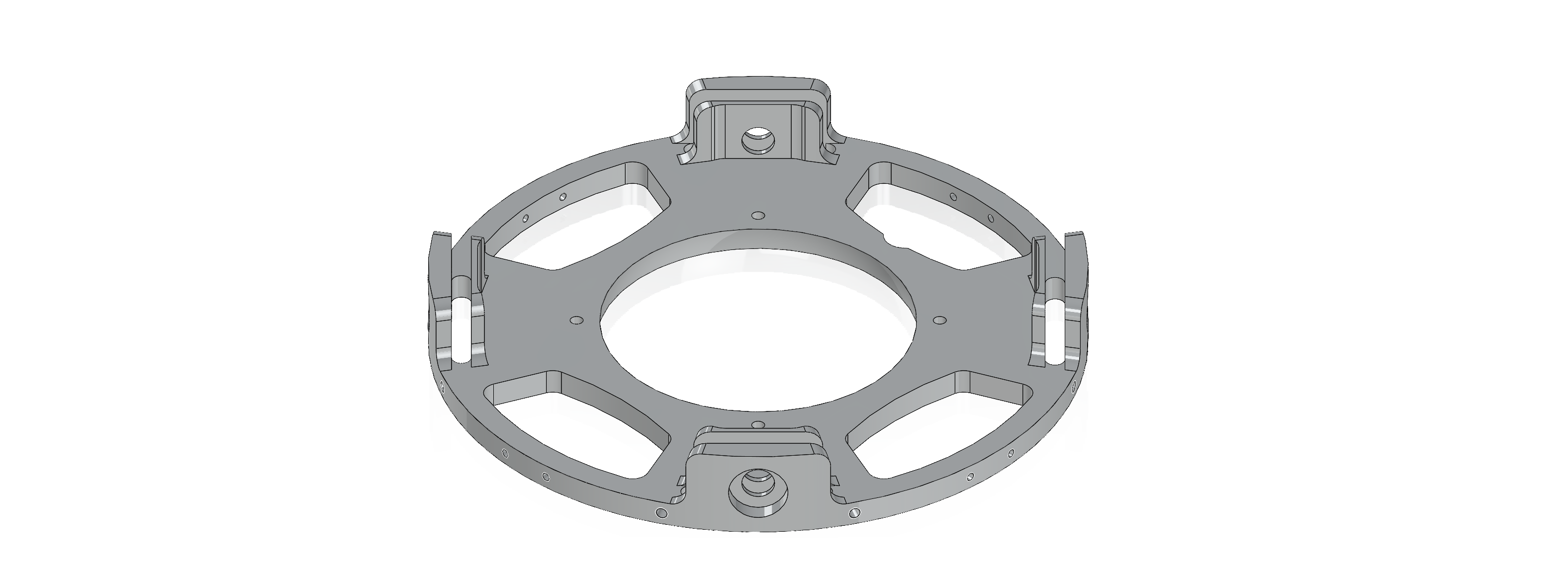
The Thrust_Plate is one of the main components of Engine Bay. It is responsible for the full integration and fixation of the Engine as well as the distribution of its Thrust through the Internal Structure. It also offers multiple fixation points for the bottom part of the fins and for the Fixation Trees, which are the parts that fixate the Boattail to the Thrust_Plate.
¶ Definitions and Abbreviations
- EB: Engine Bay
- FT: Fixation Tree
- CFRP: Carbon-fiber-reinforced polymers
- ABR: Anti-Buckling Ring
- DS-EB: Dual-Stage Engine Bay
- SS-EB: Single-Stage Engine Bay
¶ Relevant Knowledge Needed
The thrust plate is connected to the rest of the internal structure of the Engine Bay via 4 rods that are fixed to it with the help of x4 M8 screws.
This year’s thurst plate requires important adaptations to fit DEMO-B1:
- Ring-Shape to fit the rounded top of the engine and piping
- Thicker thrust plate (integrates an engine with over twice the thrust capacity of DEMO-A2)
Due to the wider diameter of the rocket (Dint = 200mm), more surface has been able to be cleared without affecting the stiffness of the component too much.
Due to the length of the boattail, additional support was required to anchor it to the thrust plate at multiple points, and a new way to link both components had to be developed.
¶ Requirements and Design Criteria
The main requirements that served as the deciding factors were the following:
-
2024_C_SE_ST_ENGINE-BAY_REQ_08
Fins fixation
The ENGB shall allow for the fins fixation. -
2024_C_SE_ST_ENGINE-BAY_REQ_11
Engine bay structure mass
The total mass of the ENGB structure shall be [6000][+/-600]g. -
2024_C_SE_ST_ENGINE-BAY_REQ_12
Structure type
The ENGB structure shall be internal so that its inside may be radially accessed. -
[2024_C_SE_PR_REQ_02]
Total impulse
The PR shall produce an impulse of [57 000][+/-500]Ns.
(Which for a 12s burn time translates to a constant force of roughly 5kN
¶ Design Options
Despite the many changes in the requirements for Firehorn's Thrust Plate, the integration of the part to the rest of the engine bay remained the same due to a similar internal structure to the one on Nordend, with CFRP rods and anti-buckling ring.
So the Thrust Plate hasn't seen design options radically changing from one to another.
Still, some key features have seen different designs in the prototyping stage:
¶ Attachment points for the fins
This design features both M4 and M3 holes directly placed in the side of the main Thrust Plate extrusion allowing the fins to be fixed.
Compact design with easier manufacturability
Easy installation and fixation of the Fins
Requires a very thick Thust Plate which seems completely overkill for the 9km Firehorn Thrust Plate design
Might not be a good fixation design for the integrity of the Fins as it would require the fixation holes to be very close to the end of the Fins (risk of tearing them during flight)
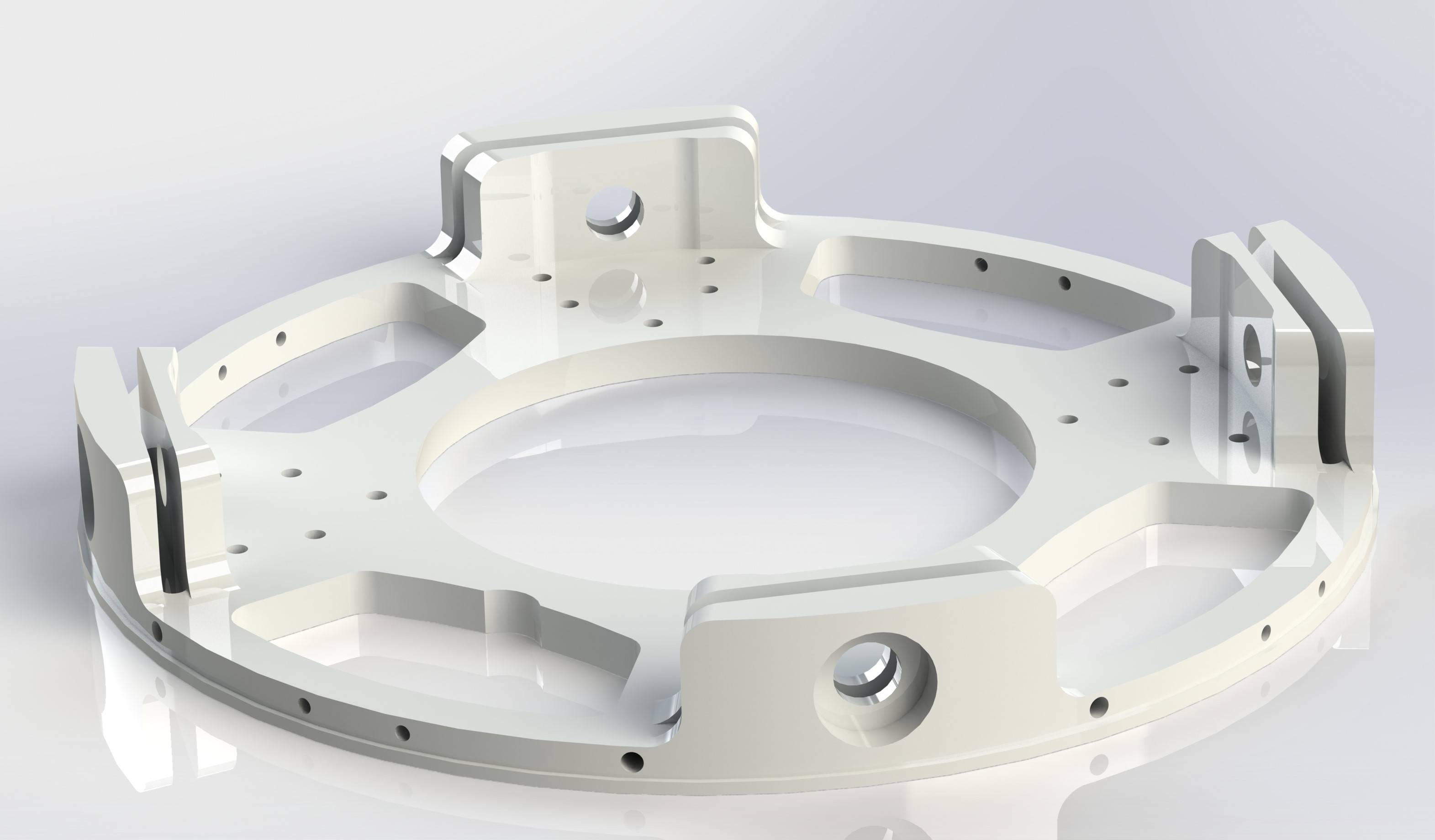
This second design offers a slimmer Thrust Plate design, with additional extrusions in the sides to allow for a slimmer part that can still act as the fixation point
Less heavy Thrust Plate
Better secured Fins (more distance between the end of the fin and the fixation hole)
More complex manufacturability
Requires the Rail Buttons to be fixed under the Thrust Plate and thus adds more complexity to the shape of the boattail
¶ Narrowing the Design Options
Both designs had their advantages and disadvantages so a thorough look at the requirements had to be done to evaluate in which case the PROs outweighed the CONs.
¶ Trade-off Results
After much consideration, we decided to give more importance to the weight loss proposed by the second design and opt for a slightly more difficult integration of the Fins and manufacturability of the Thrust Plate and boattail.
¶ Design Iterations
The Thrust Plate has seen 2 main iterations:
- The Thrust Plate designed for the Dual-Stage Engine Bay, an obsolete design of the Engine Bay having the sole purpose of integrating the engine
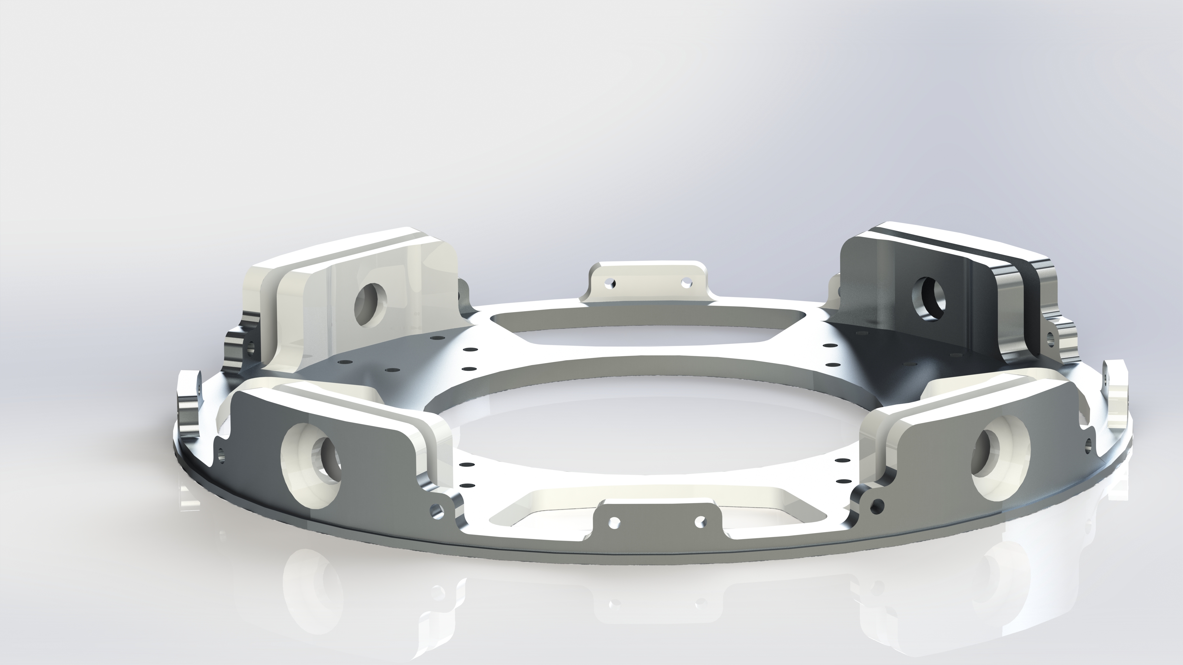
- The Thrust Plate designed for the Single-Stage Engine Bay (serving as the part integrating the engine and acting as the End Ring by being the main fixation point for the Fins and the Fixation Trees meant to hold the boattail).
¶ Iterations
As mentioned previously, this version of the Thrust Plate had the sole purpose of integrating the Engine and nothing else, it included the integrated fin fixation design and was 6mm thick, it had an "advanced mass reduction" which is essentially a mass reduction that attempts to approach as much as possible the weight reduction zones dictated by a topological study, and then another topological study is performed on top of the previous further reducing the mass while keeping a more than acceptable safety factor (x2)
Obsolete EB system
Very thick and heavy
Many surfaces of this iteration experienced very little to no stress so it was clear that we had to make multiple changes to the way we were removing mass in some places and further reinforcing others
_design.png)
This iteration also features an "advanced mass reduction" but this time with more optimal parameters for better mass reduction such as better-defined exclusion zones and a more specific area where the thrust of the Engine is applied.
_(2).png)
.png)
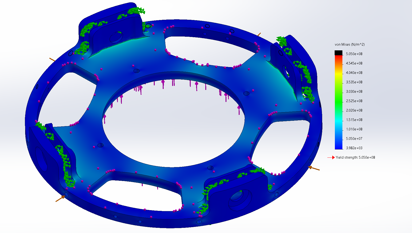
Way better distribution of the stress
Meets all requirements of the Thrust Plate with a fair bit of margin
Has some little surfaces that surpass the yield strength of Aluminium 7075-T6 (which can be discarded as they are in or surrounding the holes for the Fixation Trees which will have additional reinforcement when the screws are going through them)
Pretty complicated extruded cuts for the mass reduction which will be more difficult to represent in technical drawings and harder to manufacture
.png)
This iteration was made to attempt to get similar static load simulation results to the ones of the SS-EB Thrust Plate (Advanced Mass Reduction) iteration, for the same overall weight, but this time by making simpler the geometry of the extruded cut and therefore facilitating manufacturing.
As seen in the simulations this was not achieved.
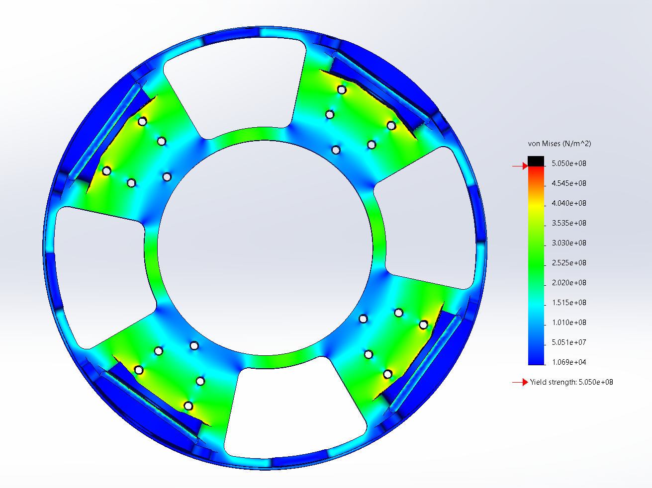

Easier manufacturing
Little to no plastic deformation zones for an even better mass reduction
¶ Simulations
The main simulations used to verify or iterate the designs of the Thrust Plate have been topological optimization studies followed by static load simulations.
Some screenshots of those can be found below:
.jpg)
Topological optimization study for a Thrust_Plate capable of withstanding a x3 safety factor in early development in November.
¶ Specificities on the simulations
¶ Topological optimization studies
For all the topological optimization studies performed on the Thrust Plate iterations after the change to the SS-EB was made, we agreed upon a normalized set of parameters to assess fairly the performance from one design to another:
-
Fixtures: Fixed geometry fixtures in the circular-threaded surfaces in the extrusion, due to the M8 screws blocking in all dimensions that segment of the part. Roller fixtures at the bottom and side surfaces inside of the 4 lateral extrusions, simulating the presence of the CFRP rods that prevent the part from deformating in the direction normal to the surface.
-
External loads: A 10kN force in the z-axis along the surface that is in contact with the engine (representing the constant force of 5kN exerted by the engine during the burning sequence with an x2 safety factor). A 9kN radial force along the entire radial-most surface of the Thrust_Plate simulating the maximum estimated force exerted by the fins and panels during the point of maximum aerodynamic pressure (with an x2 safety factor).
-
Goals and constraints: Minimize Mass for a stress constraint of x1 the yield strength (this makes the topological simulation find the best areas where mass can be removed while keeping a x2 safety factor ensuring that the part can withstand the predicted loads)
-
Manufacturing controls: Quarter symmetry control in the x and z axis.
-
Preserved regions: All the surfaces of the extrusions are meant to serve as attachment points for CFRP rods. The radial-most surfaces are meant to serve as contact surfaces for the fins to distribute their load. The threaded holes are meant to serve as the attachment points for the Fixation_Trees. The flat and cylindrical surfaces are in direct contact with the engine, as well as its fixation holes.
-
Mesh quality: (Finest) Jacobian ratio of 1, 0.5mm element size, 0.45mm minimum element size.
_cas_de_charge.png)
Visualization of the loads applied
_fixtures.png)
Close-up of one of the 4 extrusions and their fixture surfaces
_zones_exclusion.png)
Display of the Preserved/Boundary regions
¶ Static Load simulations
Similarly to the topological optimization simulations, we agreed upon a normalized set of parameters to assess fairly the performance from one design to another and see if a mass carving design was too big and made the Thrust_Plate design not perform to our standards:
-
Fixtures: Fixed geometry fixtures in the circular-threaded surfaces in the extrusion, due to the M8 screws blocking in all dimensions that segment of the part. Roller fixtures at the bottom and side surfaces inside of the 4 lateral extrusions, simulating the presence of the CFRP rods that prevent the part from deformating in the direction normal to the surface.
-
External loads: A 10kN force in the z-axis along the surface that is in contact with the engine (representing the force of 5kN exerted by the engine during the burning sequence with an x2 safety factor). A 9kN radial force along the entire radial-most surface of the Thrust_Plate simulating the maximum estimated force exerted by the fins and panels during the point of maximum aerodynamic pressure (with an x2 safety factor).
-
Mesh quality: (Finest) Jacobian ratio of 1, 0.5mm element size, 0.45mm minimum element size.
_staticload_simulation.png)
¶ Extras (Generatively Designed EB)
A fully generatively designed Thrust Plate is also a design option that we would like to implement and benchmark. By creating a single additively manufactured part that covers the functionalities and features of both the Fixation Trees and the Thrust Plate, we could be able to make the lower part of the Engine Bay even more resistant to the loads discussed above, while at the same time making the Engine Bay assembly procedure easier and reducing manufacturing costs. The first results so far are exciting, but an iteration that offers these same features while having a similar mass (450g) to the more conventional assembly design is still not feasible right now. Some further research and attempts will be done in the following months, in the hopes of achieving this purpose.
.png)
Generatively Designed EB V1
¶ Trade-off Results
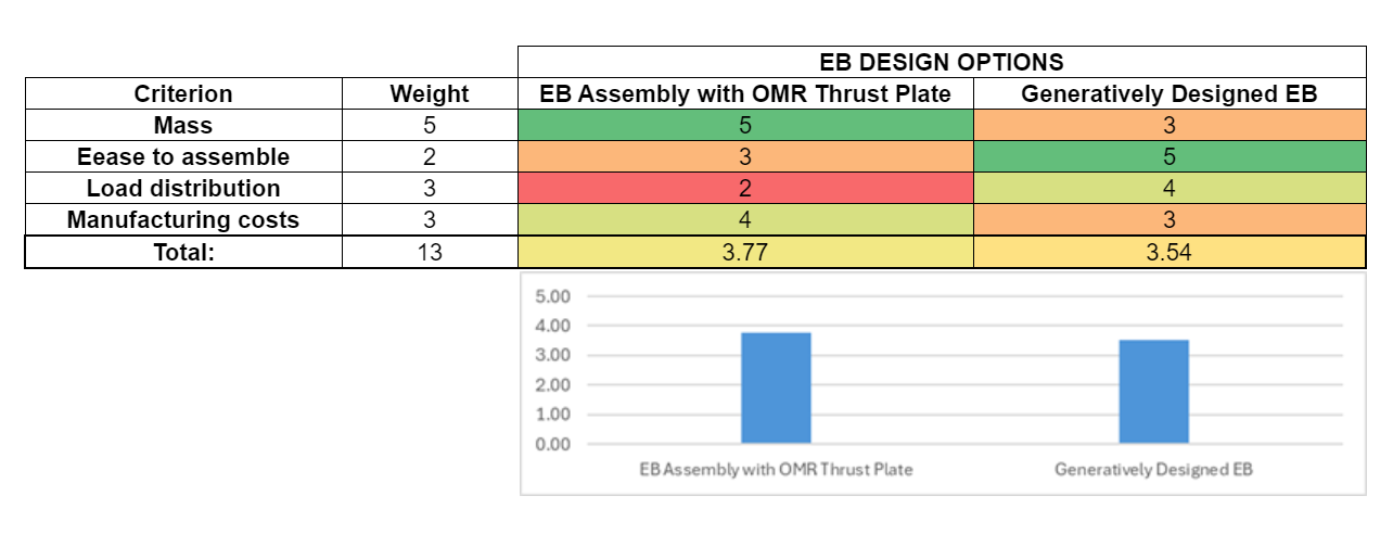
Currently, our selected Thrust Plate design is the conventionally CNCed one with the OMR configuration. However, should a generatively designed Engine Bay version with a comparable mass to the current assembly be achieved in the coming weeks, our primary focus will shift to the latter design. This design choice is motivated by the GDEB design's ability to provide the same advantages as the OMR configuration, coupled with easier integration of the Engine Bay and its components into Firehorn as well as a more uniform distribution of loads throughout the entire EB structure.
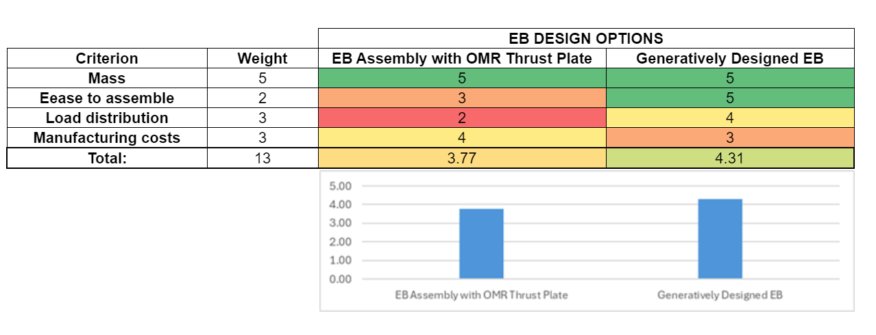
Current Decision Matrix:
Expected future Decision Matrix: