¶ 2024_C_ST_Thrust-plate_FEA
This document aims to present the method used to analyse with finite elements software the thrustplate of the Firehorn rocket.
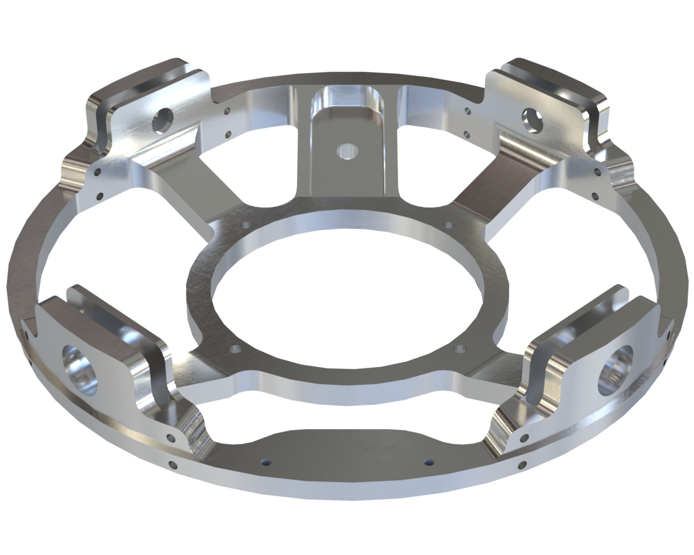
¶ Geometry and Function
The thrustplate is the part directly connected to the engine of Firehorn, therefore it is the first part that reacts to the engine thrust (7.5kN for Firehorn 9 km). The thrustplate is also connected to the Engine bay through the internal structure system, where the four ears on the thrustplate hold four carbon fiber rods which make up the structure. The hold-down system is directly fixed to the thrustplate and the latter also holds the boattail through 12 different screw holes under each ear.
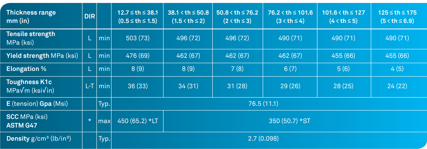
¶ Material
The thrustplate is machined in 2050-T84 alloy. This alloy has the following properties:
¶ Load case
The thrust plate must withstand the loads generated by the engine and by the hold-down system in the case where this system is still active and the thrust plate fixed to the ground. Therefore, two load cases are to be tested.
- 2024_C_SE_ST_ENGINE-BAY_REQ_18 Thrustplate load case
The FH I Thrustplate shall withstand compressive loads of [15000]N. - 2024_C_SE_ST_REQ_37 Margins of safety for simulation validation
Unless specified otherwise, all parts shall be designed to withstand their design load with an additionnal Margin of Safety (relative to the elastic limit or other applicable failure criterion) depending on the part's nature: MoS 0.25 for all static simulations, MoS 3 for all buckling load cases, MoS 3 for all parts designed via generative algorithms.
¶ Applicable and Reference Documents
¶ Finite Element Analysis
¶ Software
- ANSYS Mechanical
¶ Type of simulation
- Static structural
¶ Goal of the Simulation
The goal of the simulation is to validate that the thrustplate can withstand a load of 15 kN on the designated engine surface with a MoS of 0.25, knowing that the material yield strength is 476 MPa. And in the case with the hold-down system, the thrust plate must withstand a load of 15[kN] while fixed at the hole provided for this purpose.
¶ Inputs
We use the following unit system: mm-t-N-s-mV-mA
The part is kept as is, no simplification is made.
The material properties used were:
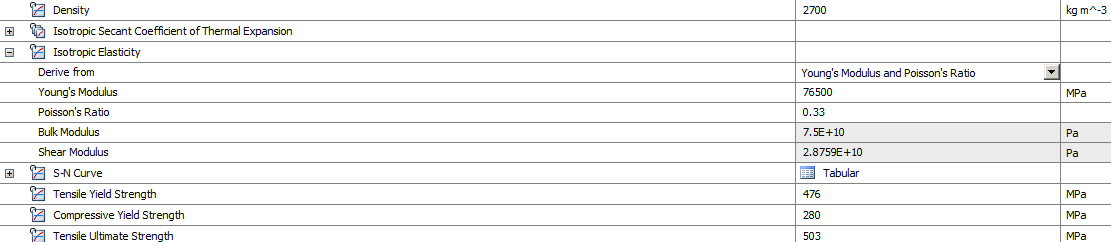
- Static simulation
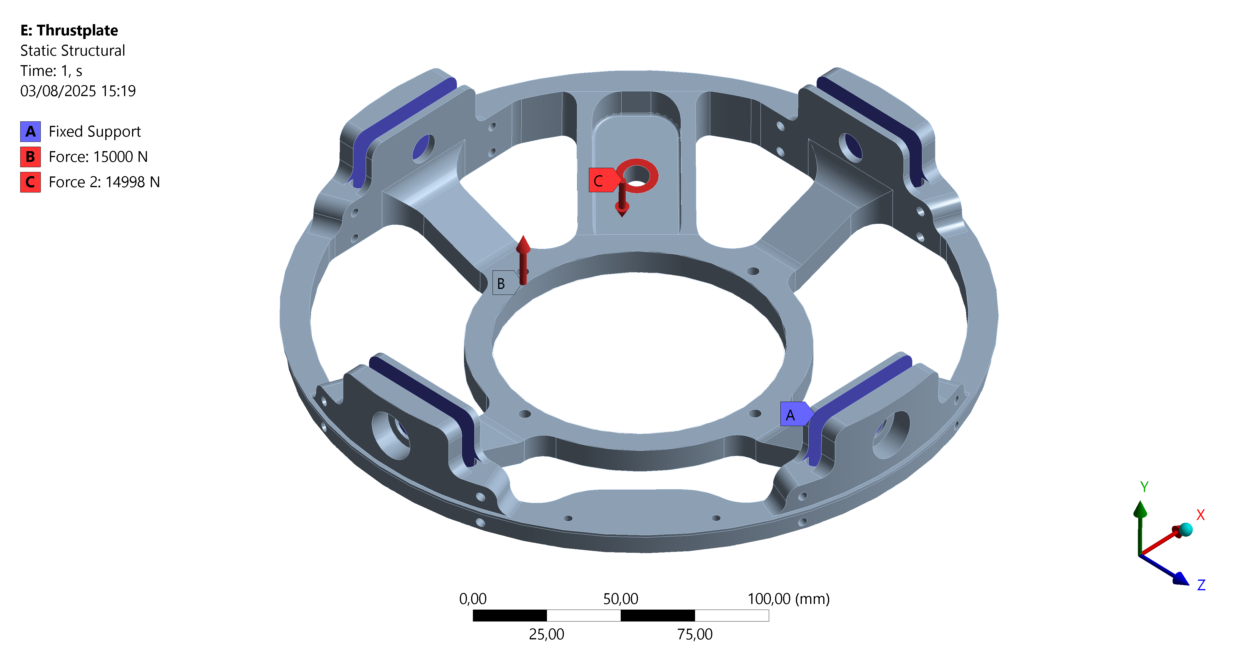
For the boundary conditions, we are in the frame of reference of the internal structure.
Two load cases are tested:
1. In-flight case
- The internal surfaces of the ears are fixed.
- A 15[kN] load is applied in the Z-direction on the interface surface with the engine.
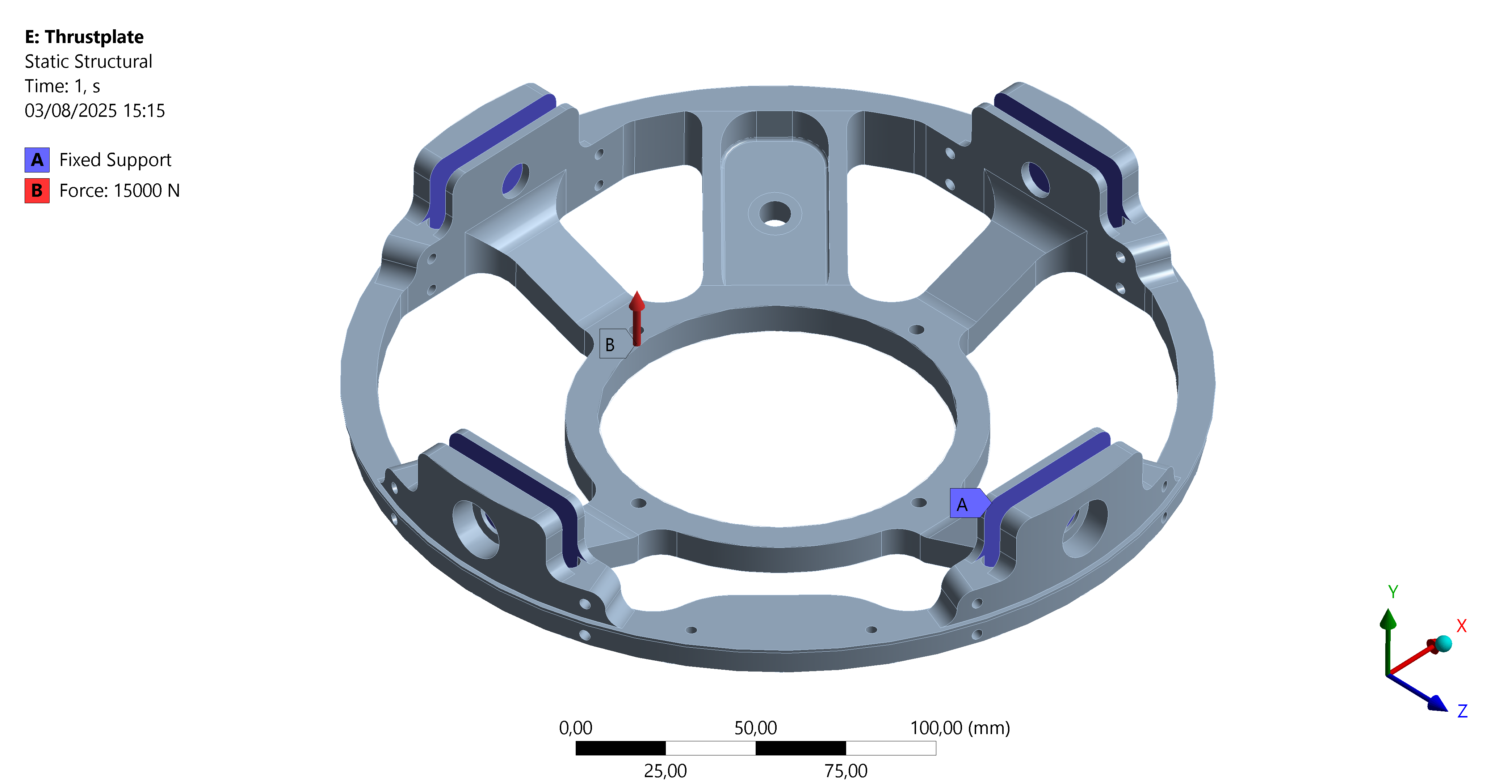
2. Hold-down case
- The internal surfaces of the ears are fixed.
- A 15[kN] load is applied in the Z-direction on the interface surface with the engine.
- A 15[kN] load is applied on the hold-down hole surface with a 5° angle.
This simulation is a static structural simulation. Non-linearities are not considered here, large deflections neither.
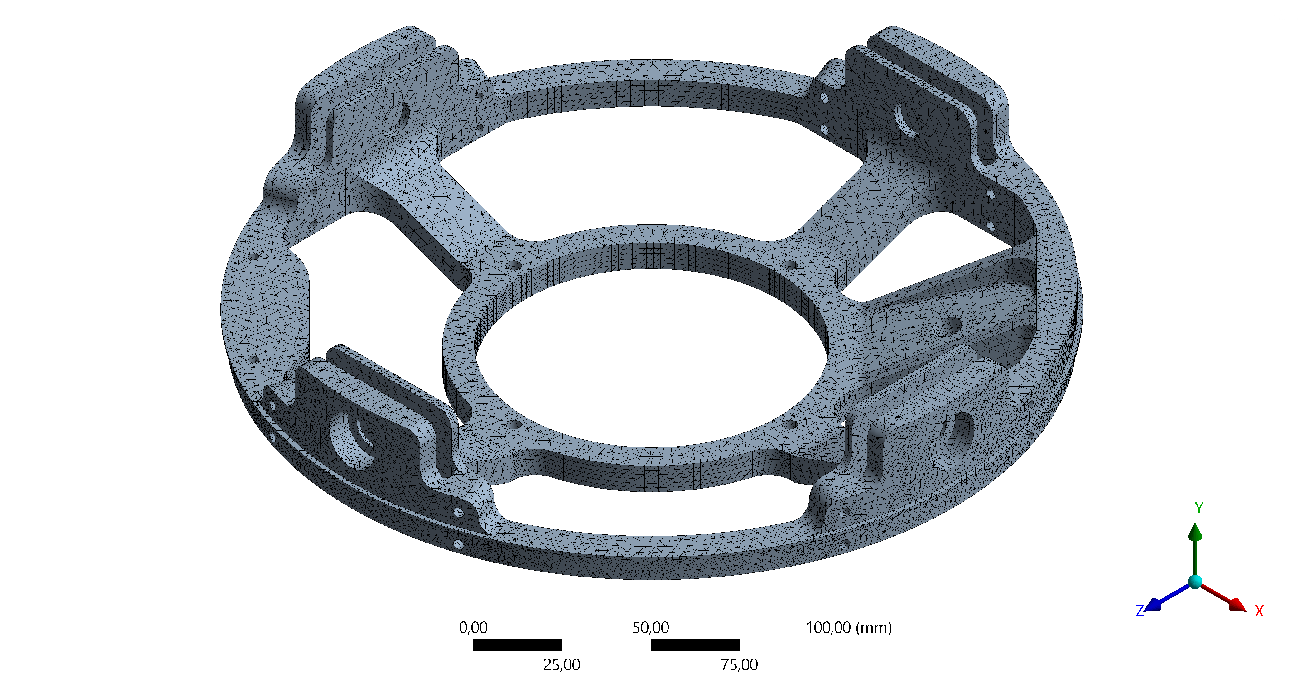
¶ Mesh
The geometry is 3D solid, so element shape is tetrahedrons with a quadratic order.
A global mesh size is defined on the whole geometry. Face meshing is added on suitable surfaces.
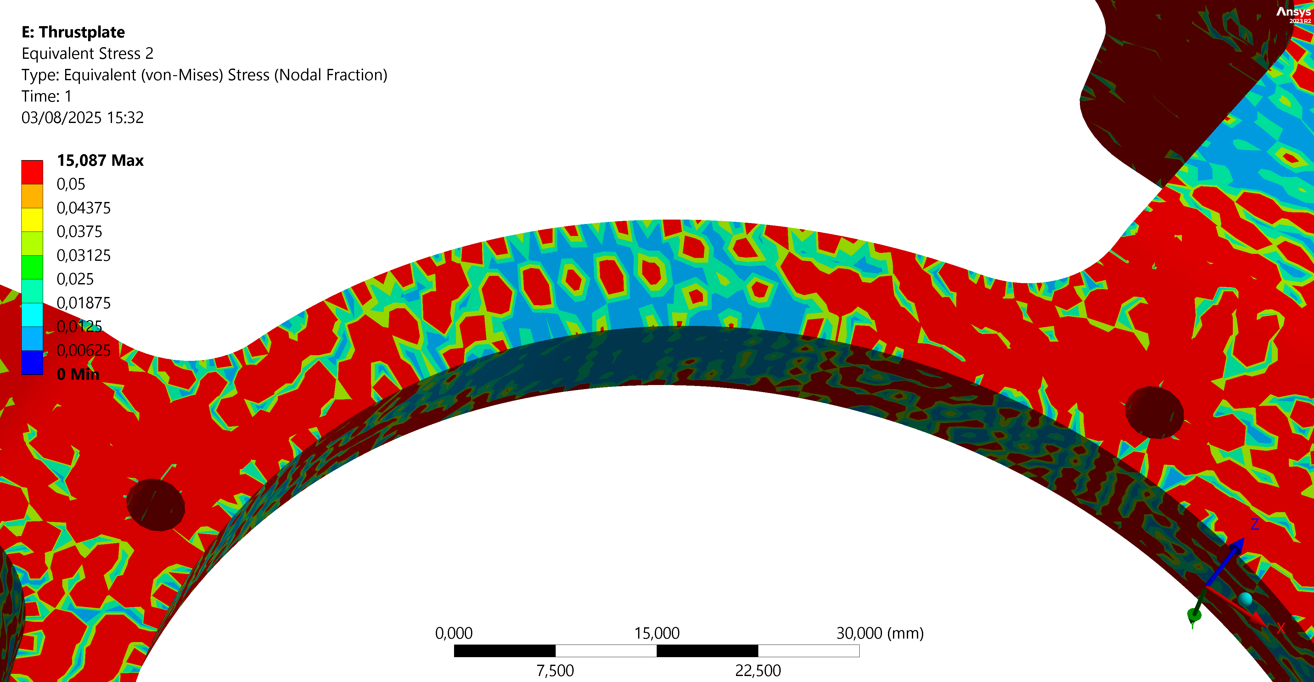
No mesh independency test was performed. However, the nodal fraction is checked to verify mesh convergence.
Looking at the maximum stress area, the nodal fraction is lower than 0.05 at this same location, confirming mesh convergence.
A global 2[mm] mesh size is used on the thrust plate.
¶ Outputs
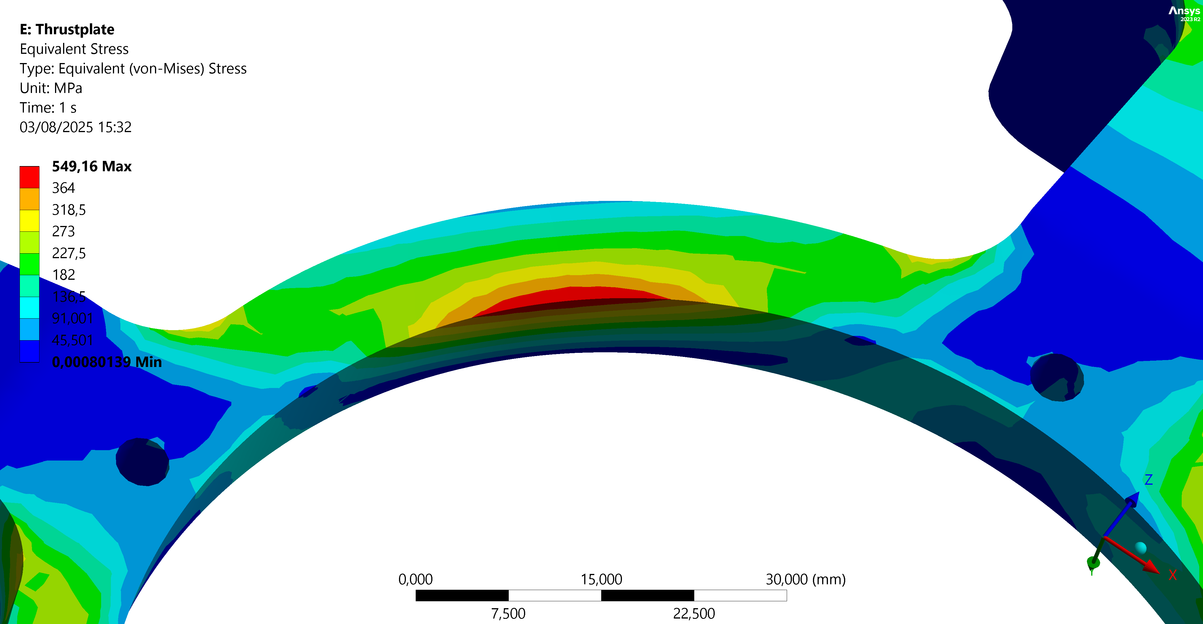
Because of the MoS 0.25, the maximum permissible stress is 455/1.25 = 364 [MPa].
With the In-flight case boundary conditions, the stress plot obtained is as follows:
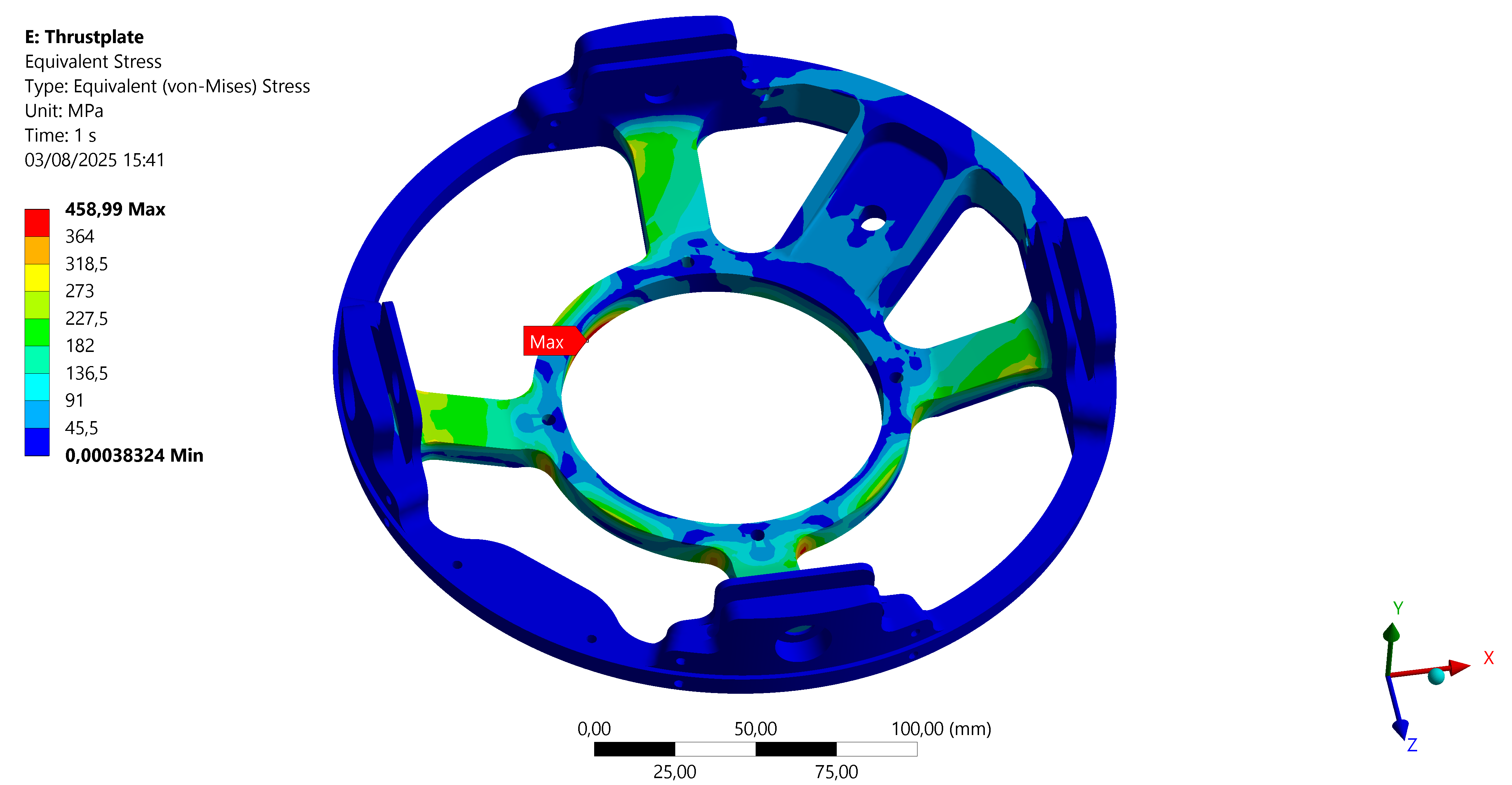
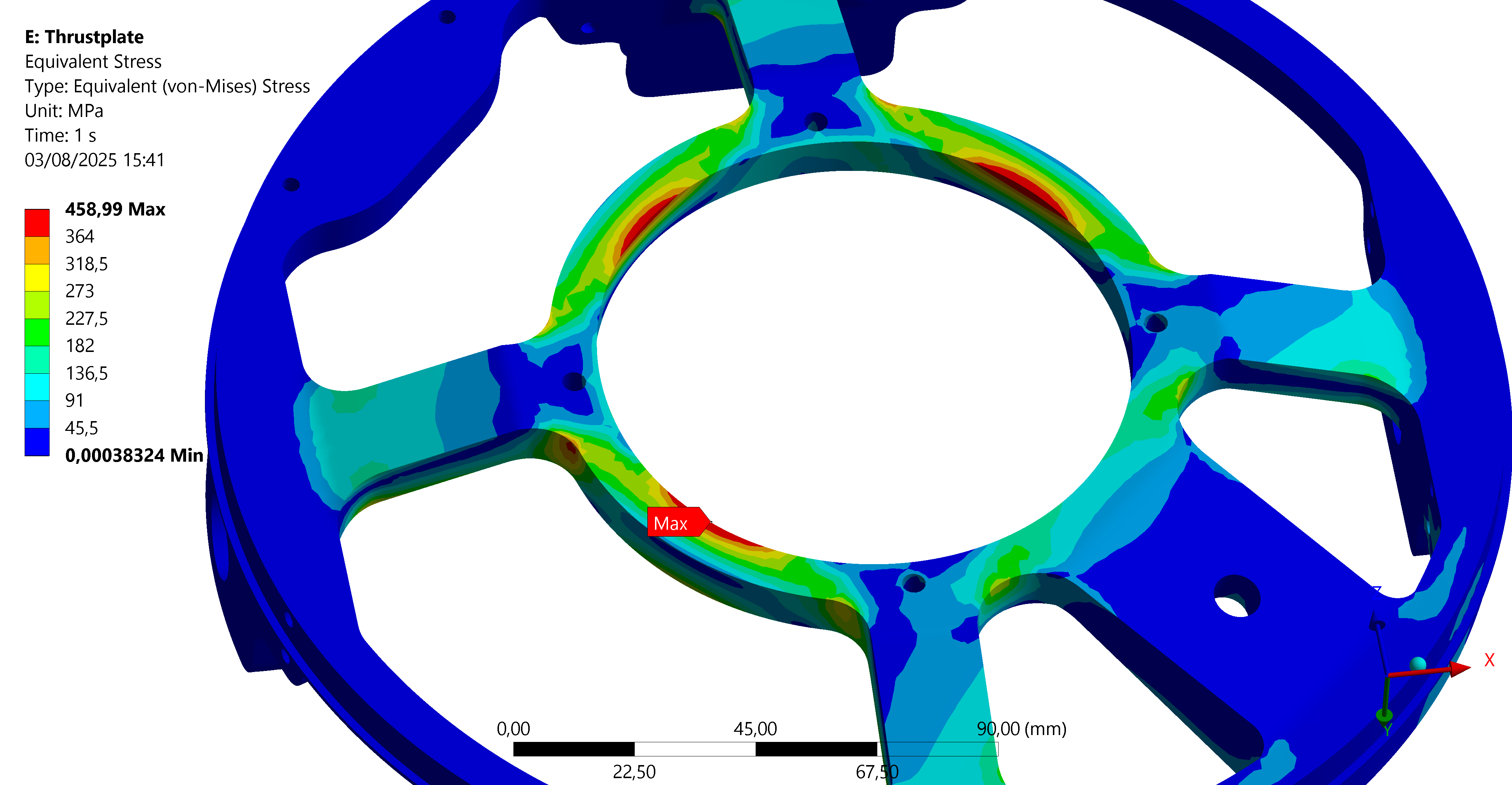
The stresses slightly exceed the yield strength on the lower surface in contact with the engine. However, since the motor is fixed there and stiffens the assembly, the actual stress will be lower and this exceedance is not a problem.
Because of the MoS 0.25, the maximum permissible stress is 455/1.25 = 364 [MPa].
With the Hold-down case boundary conditions, the stress plot obtained is as follows:
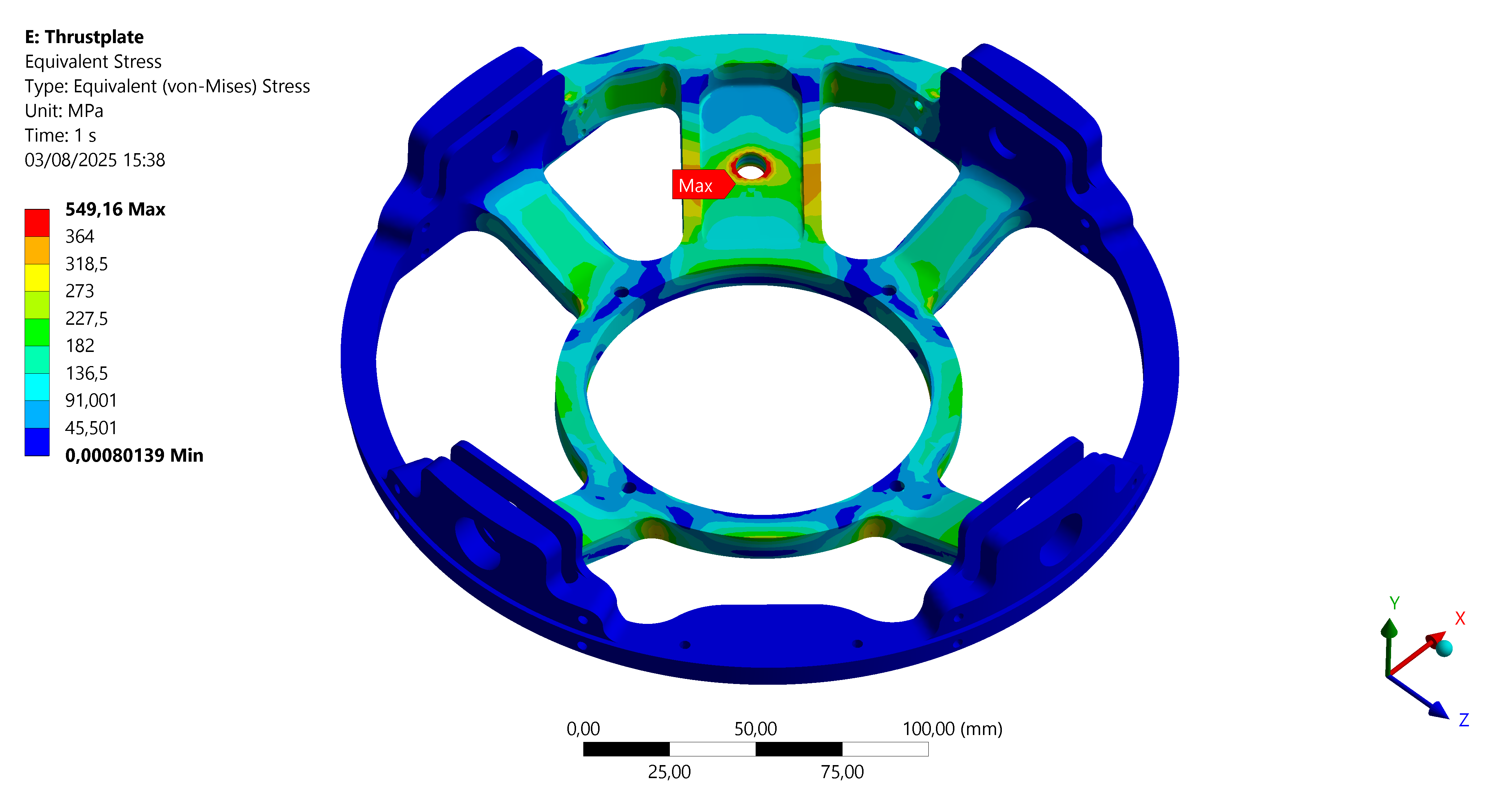
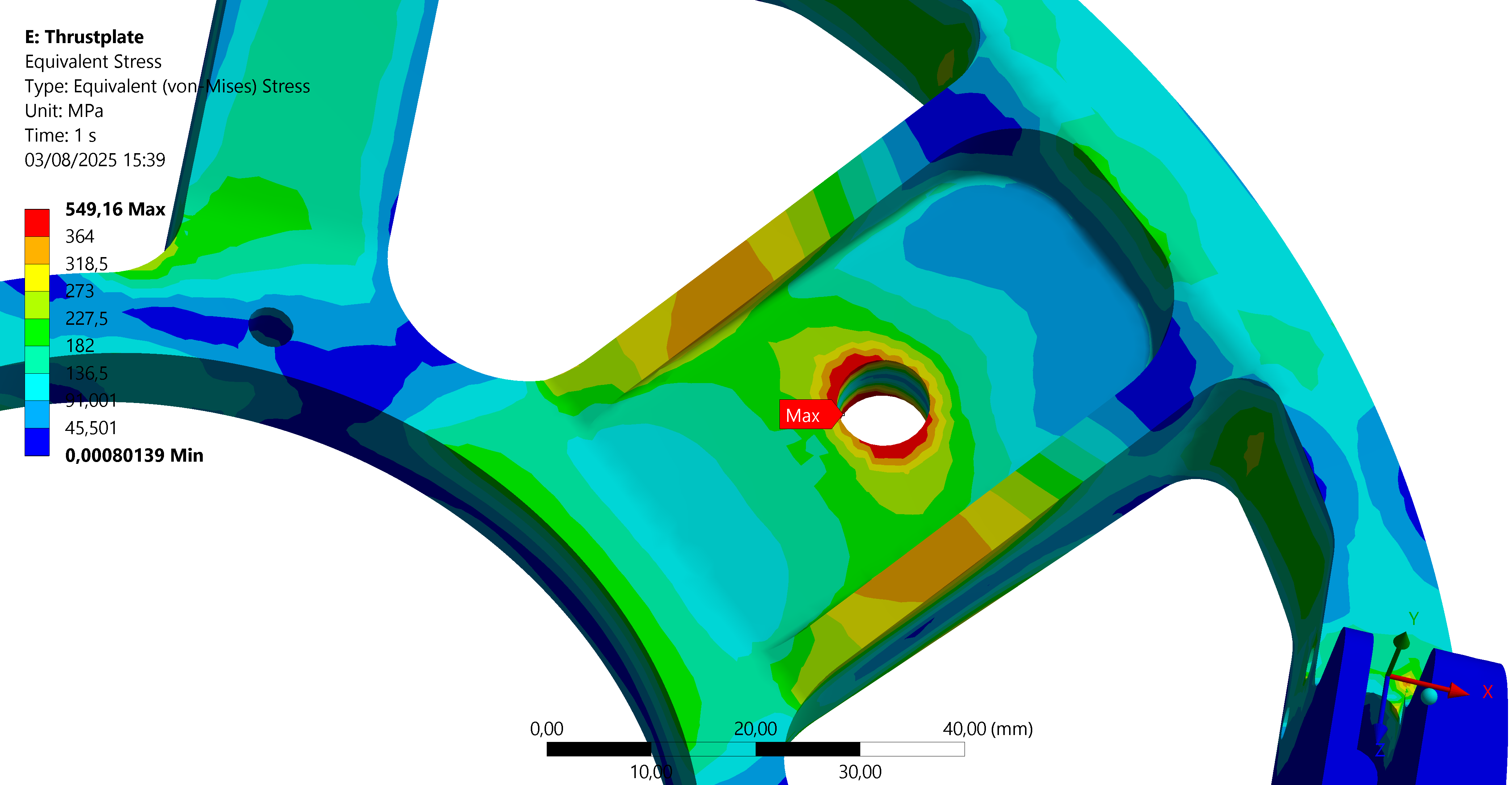
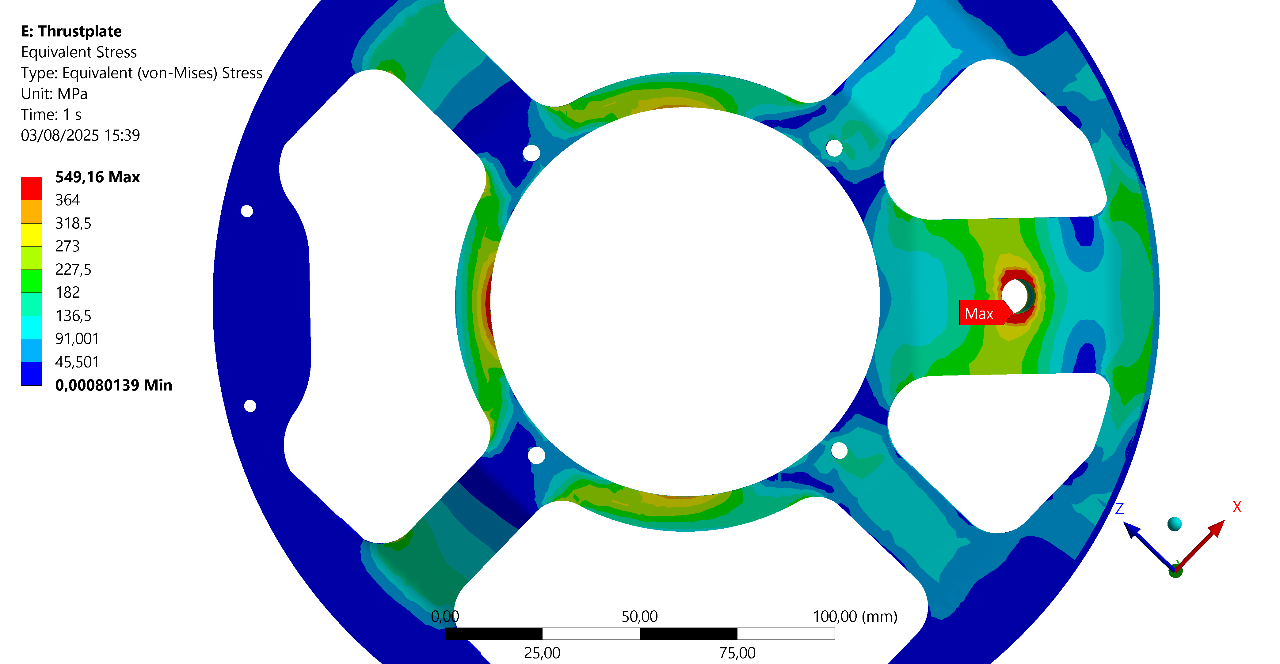
The stress is high near the hold-down hole. However this is due to a geometric singularity and because the load is applied on this surface. So this can be ignored.
Similarly to the in-flight case, the stress slightly exceeds the yield strength on the contact surface with the engine. But because of the added rigidity due to the engine not modeled here, this is acceptable.
¶ Interpretation
¶ Simulation validity
Since the mesh is converged, showed by the nodal fraction criterion, this simulation is valid. The results can therefore be used.
In order to improve the accuracy of the simulations, an assembly simulation with the engine to add its induced rigidity could be carried out but this is not essential.
¶ Conclusions
This analysis shows that the thrust plate withstands the loads during the in-flight case and the hold-down case.
In both cases, only small areas exceed the yield strength, which is not an issue since the engine will add rigidity to the internal ring.