¶ Introduction
¶ Purpose, Objective and Scope
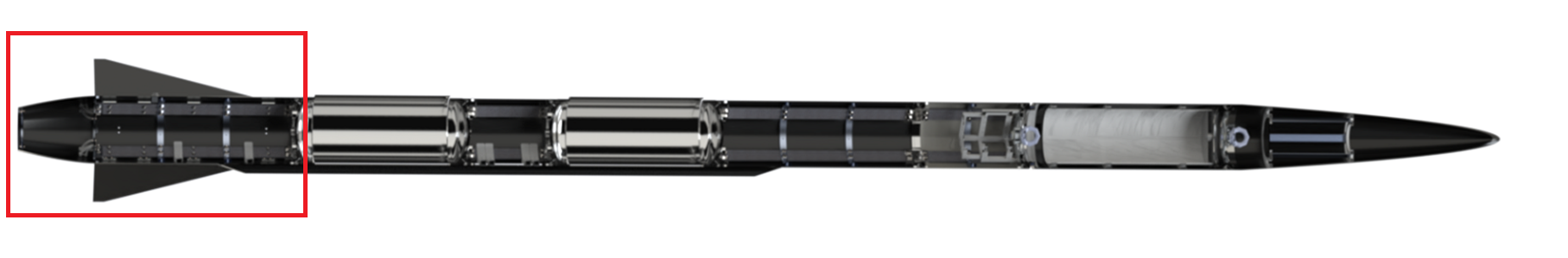
This document presents the design and the engineering process behind the conception of the thrust plate of the engine bay for the Firehorn rocket.
¶ Definitions and Abbreviations
- ST: Structure
- PR: Propulsion
- FH: Firehorn
- EB: Engine Bay
- CFRP: Carbon-fiber-reinforced polymers
- ABR: Anti-Buckling Ring
- FEA: Finite Element Analysis
¶ Applicable and Reference Documents
- Firehorn_Fluid_System
- 2024_C_ST_ENGINE-BAY_DJF
- 2024_C_ST_ENGINE_BAY_DDF
- 2024_C_ST_THRUST-PLATE_DJF
- 2024_C_ST_THRUST-PLATE_DDF
- 2024_C_ST_BOATTAIL_DJF
- 2024_C_ST_BOATTAIL_DDF
- 2024_C_ST_FINS_DJF
- 2024_C_ST_FINS_FEA
- 2024_C_ST_THRUSTPLATE_FEA
- 2024_C_ST_RRB_DDF
¶ Requirements
- 2024_C_SE_ST_ENGINE-BAY_REQ_02 Thrust plate
The Engine Bay shall transmit the thrust from the engine to the rest of the rocket through a fixed thrust plate. - 2024_C_SE_ST_ENGINE-BAY_REQ_11 Engine bay structure mass
The total mass of the Engine Bay structure shall be maximum [7000]g. - 2024_C_SE_ST_ENGINE-BAY_REQ_18 Thrustplate load case
The FH I Thrustplate shall withstand compressive loads of [15000]N.
¶ Overview
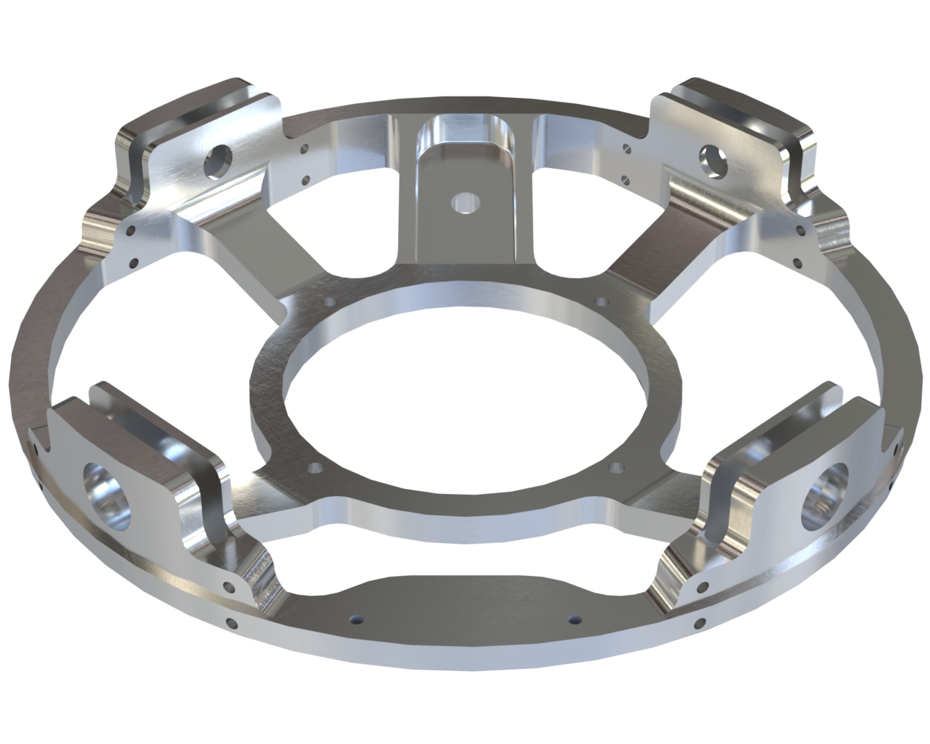
The Thrustplate is one of the main components of Engine Bay. It is responsible for the full integration and fixation of the engine as well as the distribution of its thrust through the internal structure. It also offers multiple fixation points for the boattail, the panels and a special fixation hole for the hold-down system.
¶ Main Specifications
| Specification | Value | Unit |
|---|---|---|
| Dimensions | 243 x 243 x 49.7 | [mm] |
| Mass | 657 | [g] |
| Material | Al-2050T84 | |
| Design Load | 15000 | [N] |
| Nominal load | 7500 | [N] |
| Factor of Safety | 2 | |
| Manufacturing | 5-axis CNC |
¶ Analysis and simulations
 2024_C_ST_THRUSTPLATE_FEA
¶ Technical Drawings

¶ Interfaces
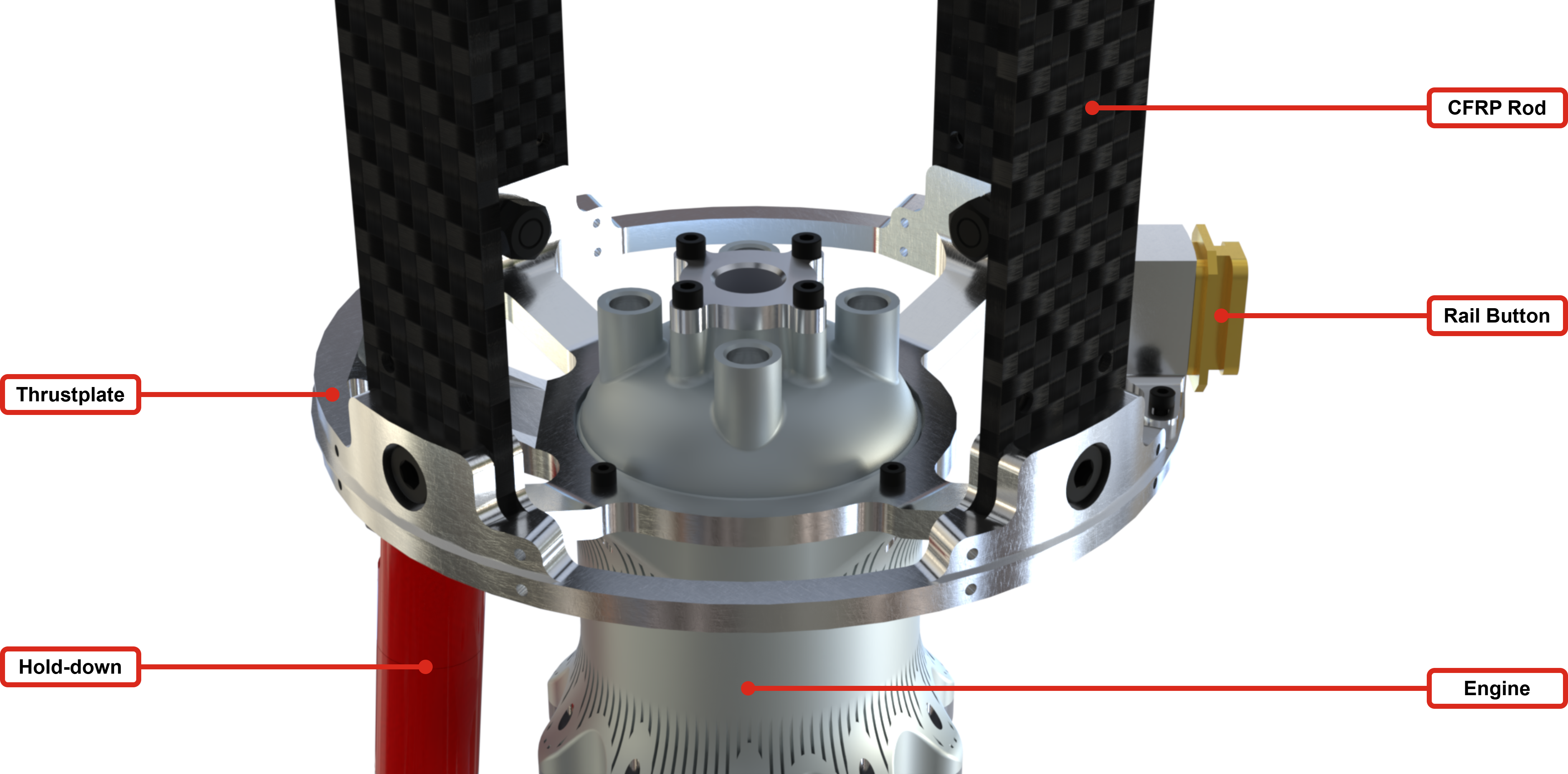
The thrustplate has several interfaces with other parts. In particular, the following systems are fixed to the thrustplate:
- Engine (with 4xM4 screws)
- Internal Structure (Ears are directly part of the thrustplate to attach the latter to the rods)
- Rail Button (with 2xM4 screws)
- Hold-down (with M8 lifting ring)
- Pannels (with 8xM4 screws)
- Boattail (with 8xM4 screws)
For more informations on the interfaces between ST and PR subsystems, please refer to the following document:
- 🔗 ST/PR Low Level Interface Management (LLIM) The Low Level Interface Management beetween ST and PR
¶ Technical Budget, Margins and Deviation
No technical budget is directly specified for the thrustplate.
The overall technical budget for the engine bay is adressed in the following document:
¶ Design Constraints
¶ Constraints for Production
The thrust plate needs to be done with a 5 axis CNC. It should be done in AL2050 T84 which is an excellent robust and lightweight metal.
¶ Constraints for Operation
The use of nuts is preferred because they help protect the thrust plate, prevent unfastening, and distribute the load over a larger surface area.
¶ Other Constraints
This thrustplate is specifically designed with the engine interface and the loads for FH 9. It will have to be redesigned for FH 30.