¶ 216400_Retractable_Rail_Button
¶ Introduction
Retractable Rail Button
The rail button makes the interfaxe between the rocket and the launch rail. Once the rocket comes out of the launch rail, the rail button shall retract inside the airfram to minimise the drag.
¶ Definitions and Abbreviations
- RBB : Rectractable Rail Button
¶ Applicable and Reference Documents
RRB Nordend
- [2023_ST_TN_H01]
- 2024_C_ST_PEI_Rail-Button
- 2025_C_ST_Rail-Button_TSP
The rail button TSP has not been done because we haven't had the time to do the test.
¶ Requirements
- 2024_C_SE_ST_INTERNAL-STRUCTURE_REQ_02Interface with EuRoc rail
The rail buttons shall be compatible with the EuRoC launch rail.
Button
Competition rail
- 2024_C_SE_ST_INTERNAL-STRUCTURE_REQ_03 Rail Buttons Load Case
Each rail button shall be able to withstand a force of [4400]N (in the radial direction of the LV).
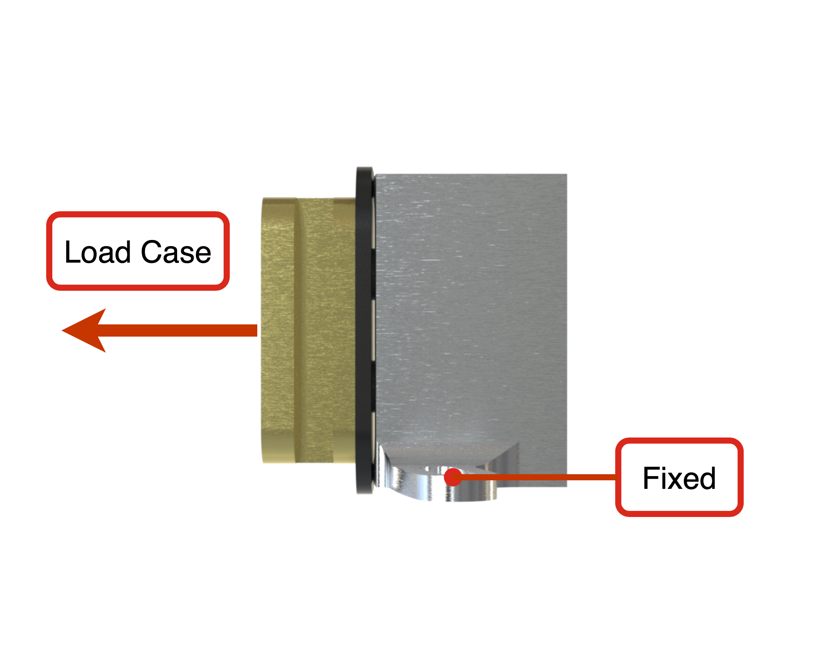
Analytic analysis
Force applied on the button in traction by the fully loaded rocket : 4400N
Shear stress formula :
Maximum elastic stress for brass = 100-300 MPa
¶ Interfaces
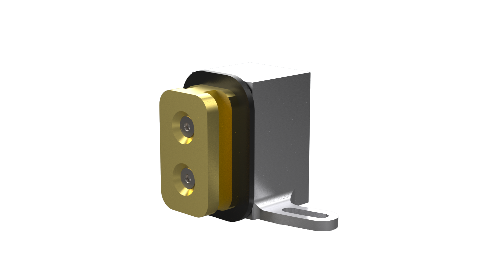
This assembly makes the connectin between the rocket and the launch rail, and it is present twice in the structure. One of them is in the engine bay on the thrust plate and another is on the upper tank level on an ABR.
- [2024_C_ST_THRUST-PLATE_DDF]2024_C_ST_THRUST-PLATE_DDF
- [2024_C_ST_ENGINE_BAY_DDF]2024_C_ST_ENGINE_BAY_DDF
- [2024_C_ST_INTERNAL-STRUCTURE_DDF]2024_C_ST_INTERNAL-STRUCTURE_DDF
¶ Overview
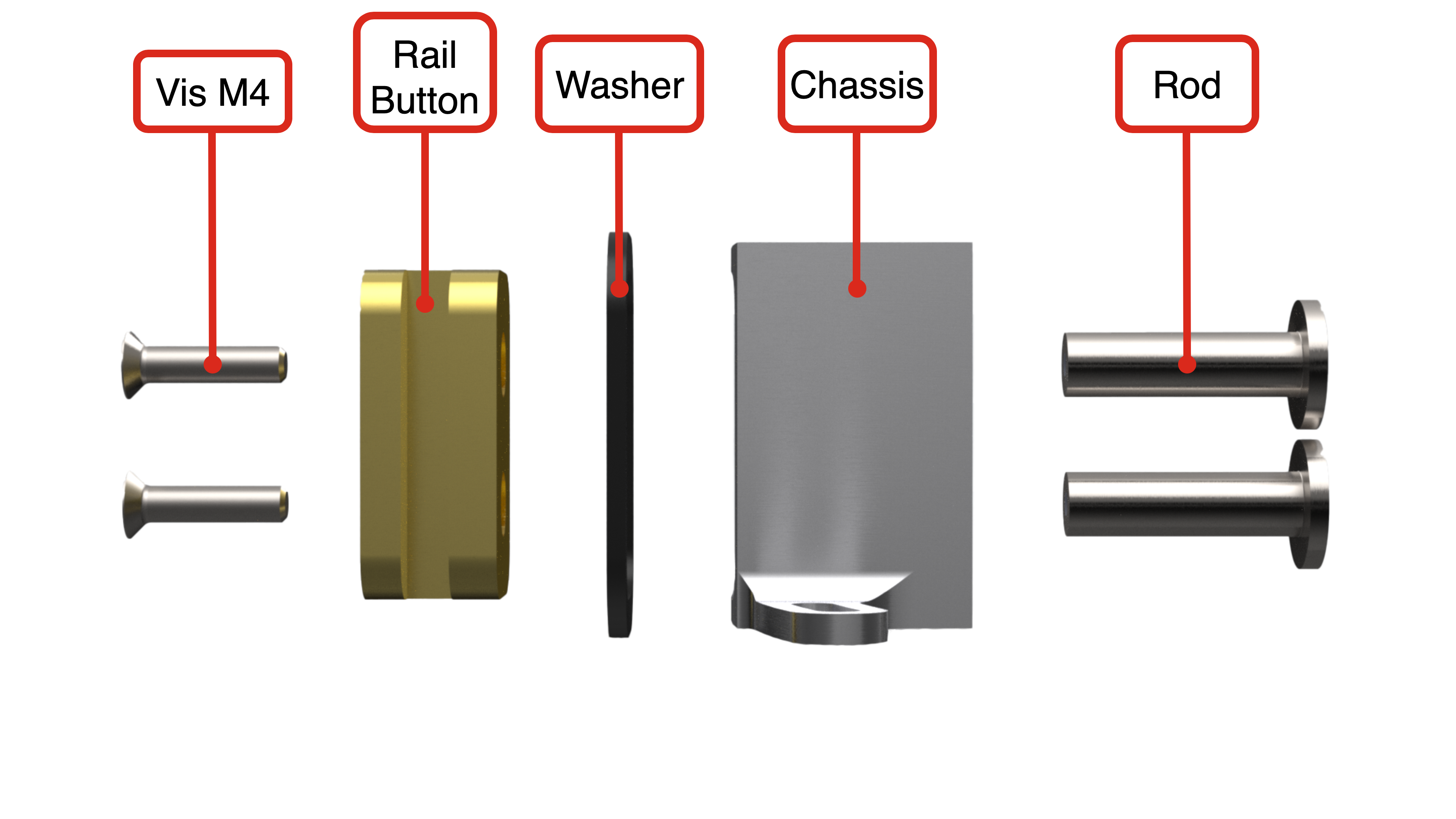
The RRB is composed of 4 different parts.
The rail button is the part that interacts directly to the launch rail. It shall withstand all the forces on the system.
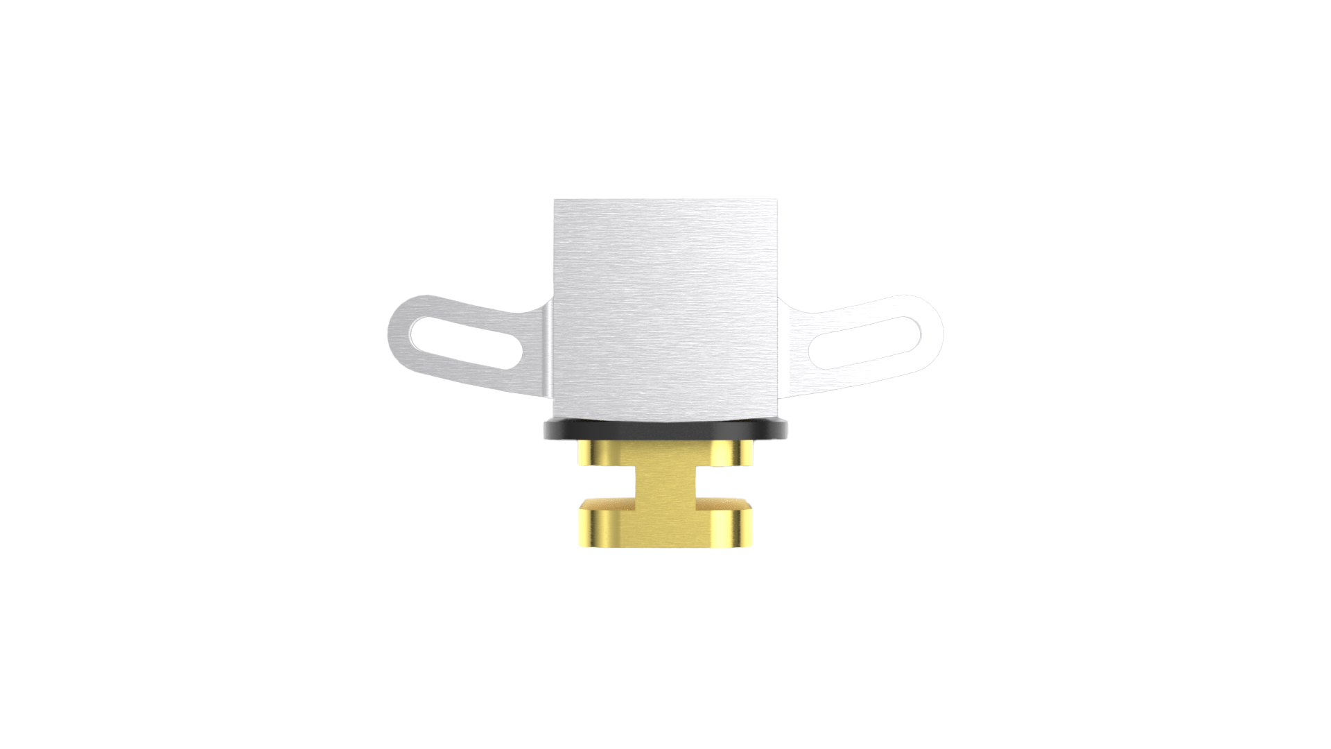
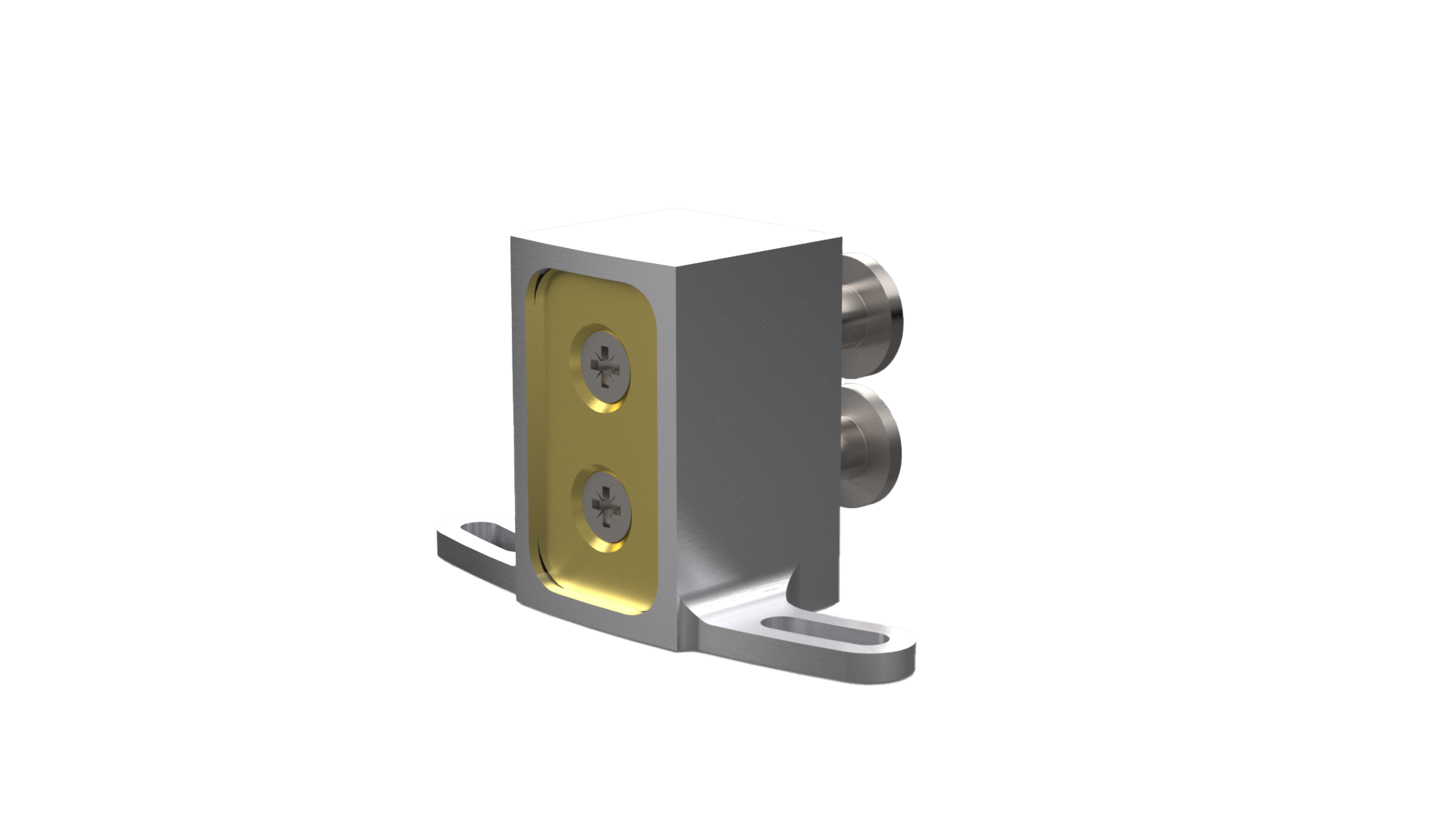
The chassis is responsible for making the connection between the rail button and the rocket, and the rail button is going to rectract into it.
The rods hold the rail button and the chassis together, and it's where the springs apply their forces in order to rectract the rail button once the rocket leaves the rail.
The washer prevents the airframe to be in contact with the lauchn rail, and improves the friction coefficient between the rail and the rocket.
¶ Parts List
¶ Parts Description
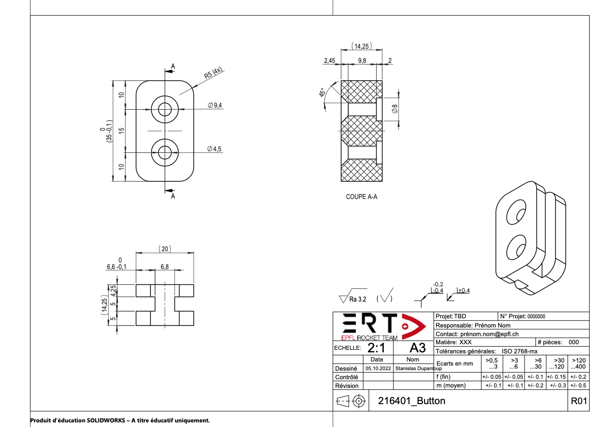
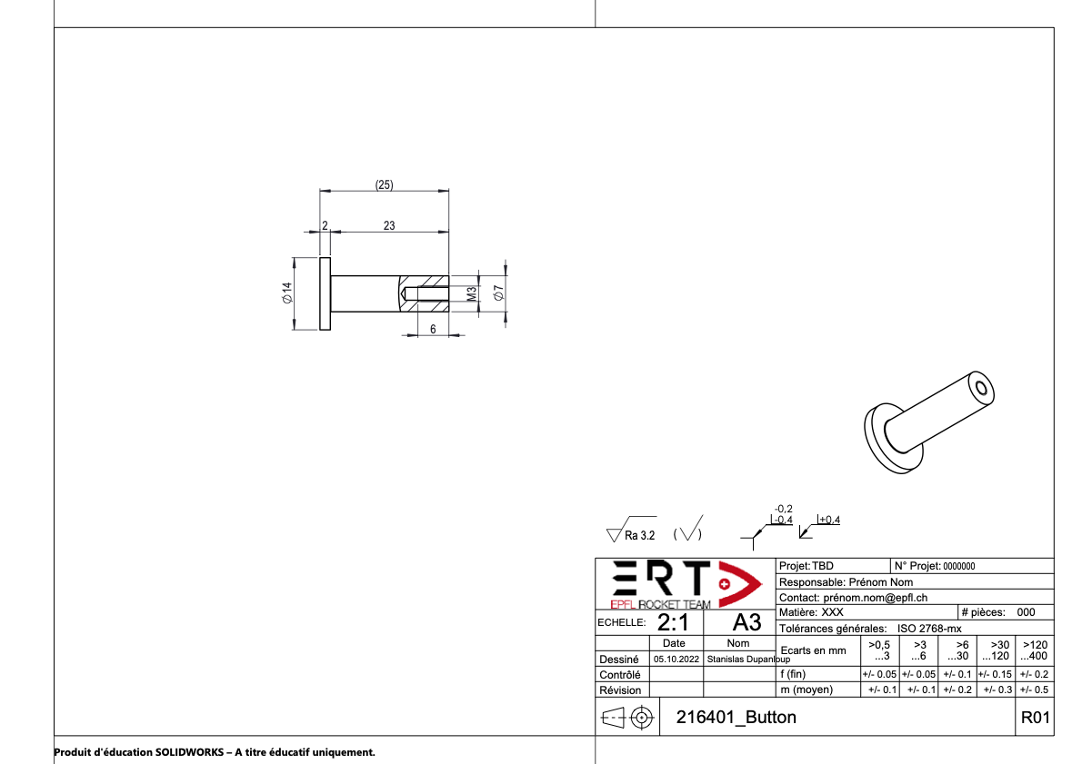
¶ 216401_Rail Button
¶ Description
It is the part that's going to be inserted in the launch rail, so it is the critical part of the system.
¶ Main Specifications
| Specification | Value | Unit |
|---|---|---|
| Dimensions | 35 x 20 x 14.25 | [mm] |
| Mass | 105 | [g] |
| Design Load | 4400 Axial | [N] |
| Factor of Safety | Included in the design load (2) | |
| Margin of Safety | 1 | |
| Manufacturing | Milling machine | |
| Fastening | 2x M4x16 countersunk head screw | |
| Material | Brass | |
| Friction coeff with Steel | 0.35 |
¶ Interfaces
The rail button is screwed to the two rods and it fits in the chassis.
¶ Traction test PEI and PETG
We first wanted to 3D print the rail button because it is a lot quicker to manufacture than to machin it.
The result of the traction test done on printed sample of PEI in order to understand the limits of this material.
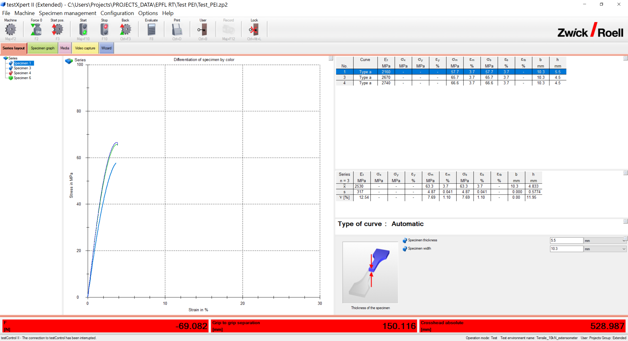
The traction test on PETG reinforced with carbon gave us approximately the same results.
We decided that the elastic limits of these material are too close to the maximal stress we have on our simulations. Furthermore, if we continue to build bigger and heavier rockets in the futur, we would have to do this transition from plastic to metal anyway.
We choose make the rail button in brass because it has a higher elastic limit than the other materials tested, and it has a good friction coefficient with steel.
¶ Analysis and Simulations
Analytic analysis
Force applied on the button in traction by the fully loaded rocket : 4400N
Shear stress formula :
Maximum stress for brass = 100-300MPa
which is smaller than 100MPa
¶ Technical Drawings
¶ Possible Improvements
This rail button is designed to be compatible with futur rockets hypotaticlly bigger and heavier. If it appears to not be strong enough, we should think about changing the geometry of the part so that the occupied space in the launch rail is maximized.
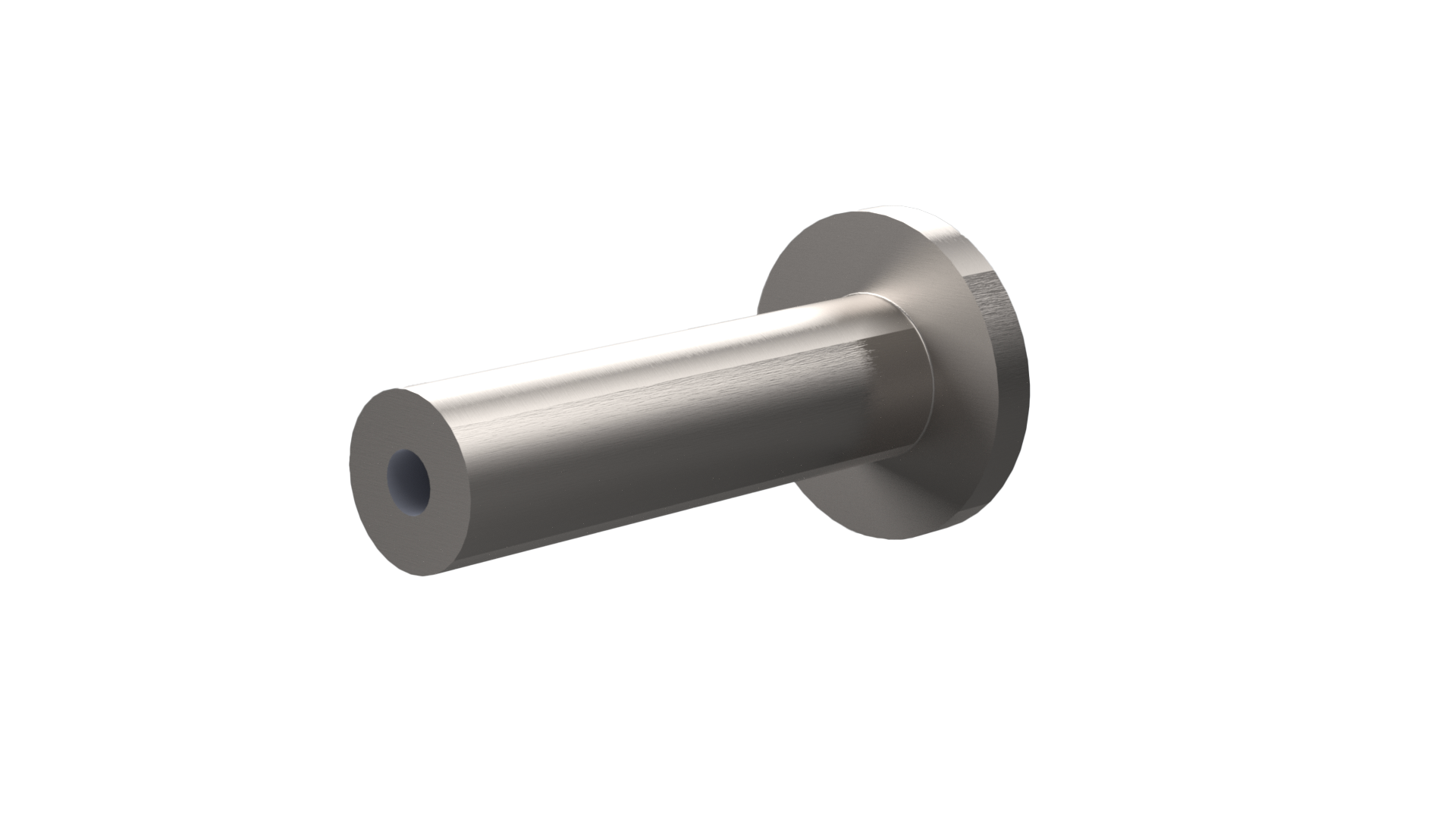
¶ 216402_Rod
¶ Description
This part ties the chassis and the button together. It is where the spring of the system is going to apply a force in order to make the rail button retract.
¶ Main Specifications
| Specification | Value | Unit |
|---|---|---|
| Dimensions | 25 x 14 x 14 | [mm] |
| Mass | 10 | [g] |
| Design Load | 2200 Axial | [N] |
| Factor of Safety | 2 | |
| Margin of Safety | 1.4 | |
| Manufacturing | Lathe | |
| Fastening | 2x M4x16 countersunk head screw | |
| Material | Steel |
¶ Interfaces
It is screwed to the rail button.
¶ Analysis and Simulations
|---------------------|-------------------------|-----------------|
| Maillage | 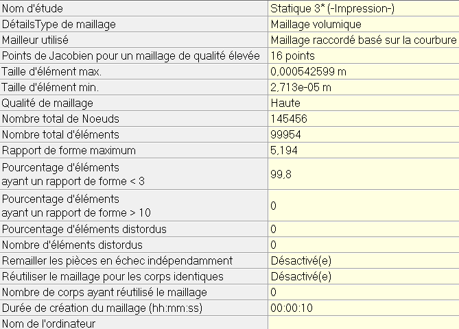 | |
| |
| Conditions de bord | 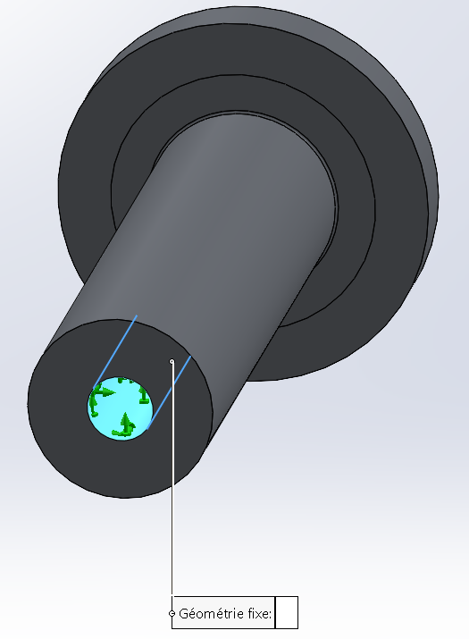 |
| 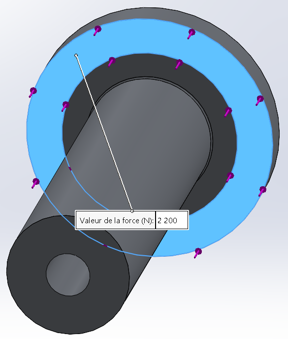 |
|
| Stress | 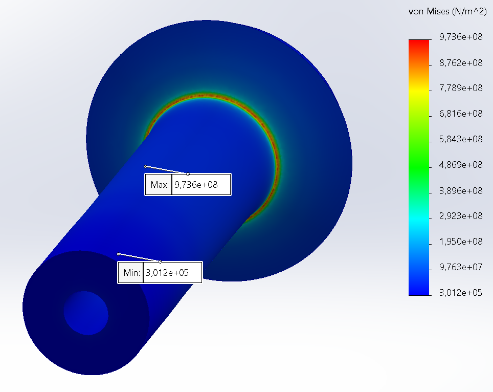 | Max = 973.6MPa |
| Stress concentration | 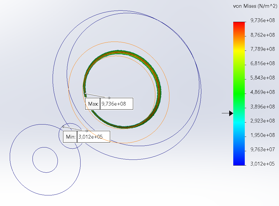 | All the stress that is superior to 355MPa is concentrated in these zones (elastic limit). These zones are very thin, which means that they won't have a big impact on the intergity of the part. We are going to test this part with the whole system in order to verify this statement. |
| Déplacement | 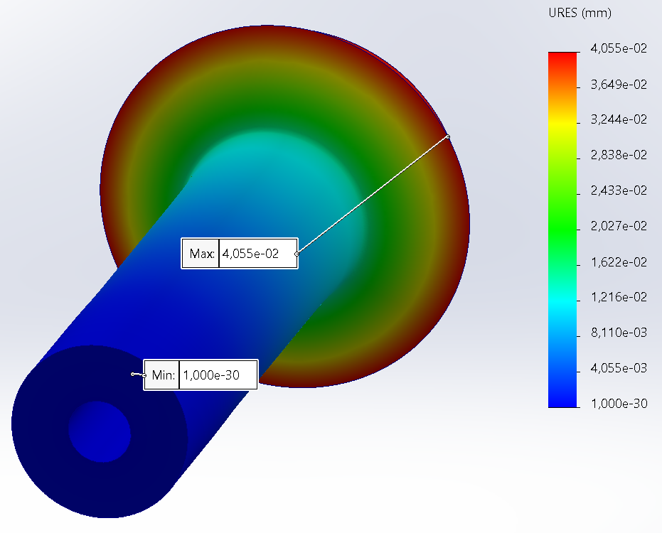 | Max = 0.041mm |
¶ Technical Drawings
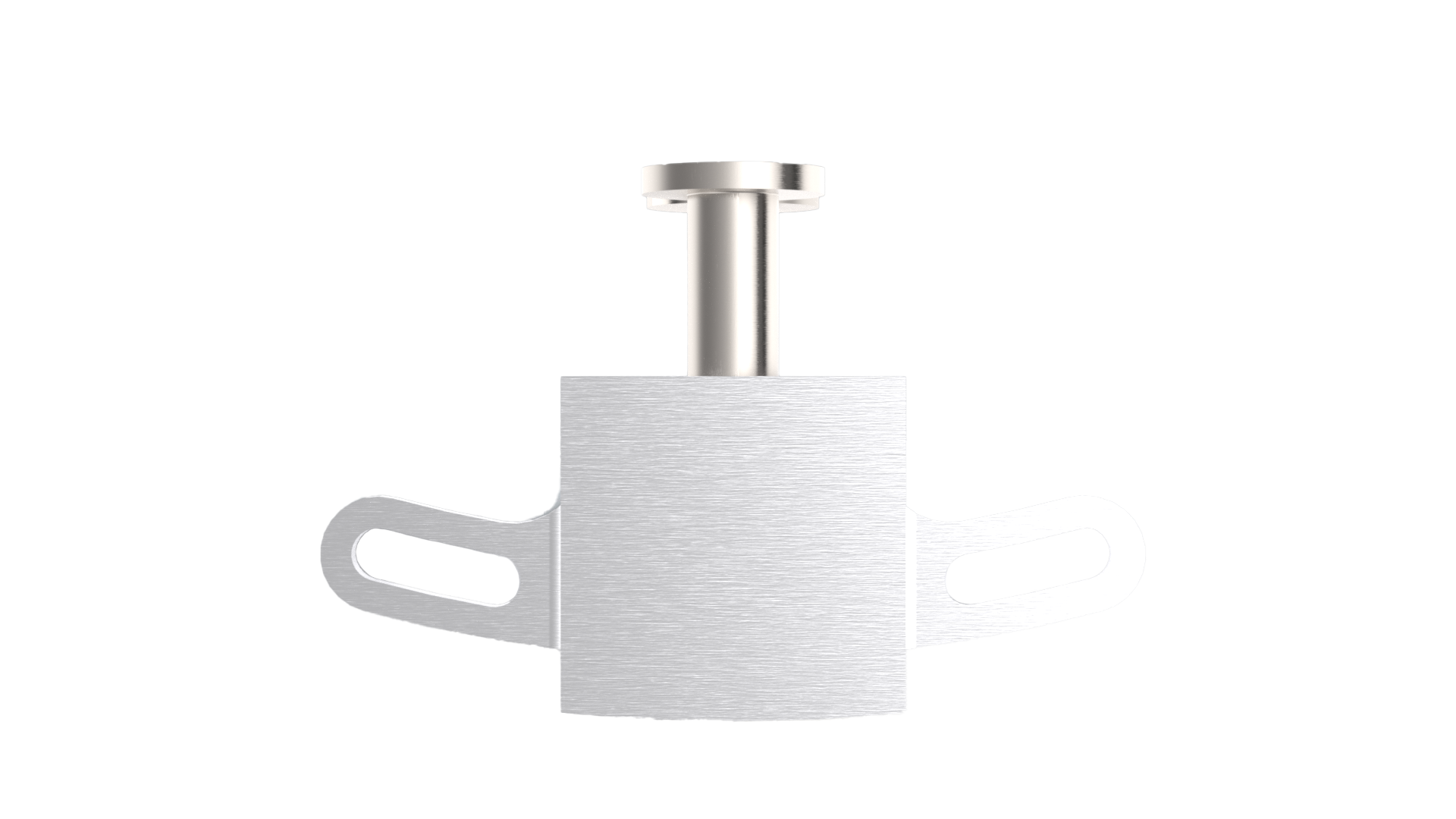
¶ 216403_Chassis
¶ Description
This part is what fixes the rail button to the structure of the rocket and it is where the rail button is going to retract during the flight.
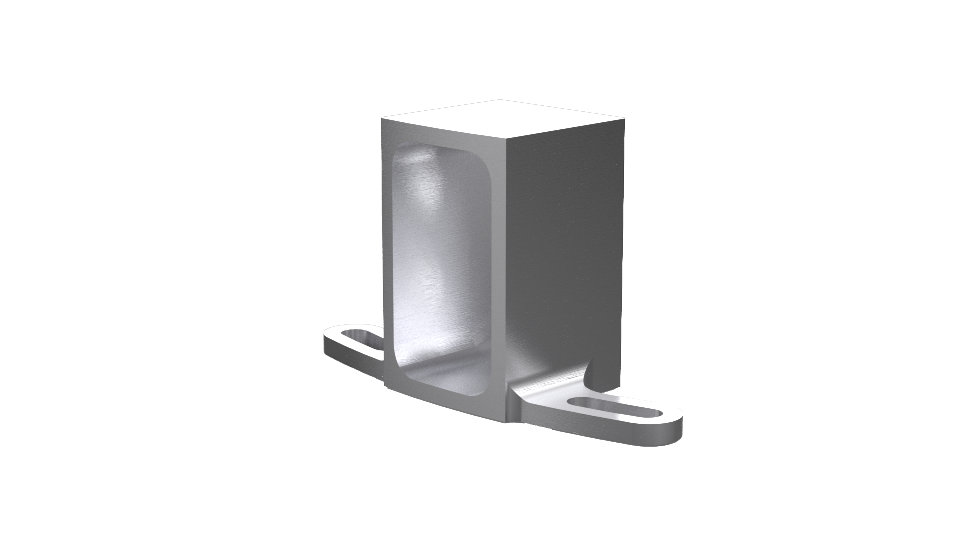
¶ Main Specifications
| Specification | Value | Unit |
|---|---|---|
| Dimensions | 69 x 40 x 24.5 | [mm] |
| Mass | 36 | [g] |
| Design Load | 4400 Axial | [N] |
| Factor of Safety | 2 | |
| Margin of Safety | 1.57 | |
| Manufacturing | 5 axis CNC | |
| Fastening | 2x M4x20 Hex bolts | |
| Material | Al 2050 |
¶ Interfaces
One chassis is screwed to the thrust plate and the other to an ABR in the pressurant bay.
¶ Analysis and Simulations
¶ Technical Drawings
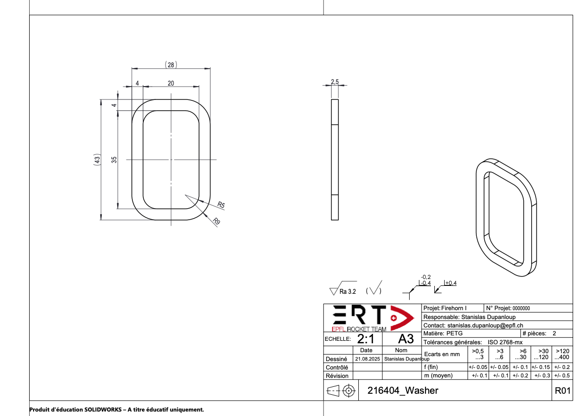
¶ 216404_Washer
¶ Description
The washer prevents the airframe to be in contact with the lauchn rail, and improves the friction coefficient between the rail and the rocket.

¶ Main Specifications
| Specification | Value | Unit |
|---|---|---|
| Dimensions | 43 x 28 x 2.5 | [mm] |
| Mass | 1.65 | [g] |
| Design Load | 0 | [N] |
| Manufacturing | 3D printing | |
| Fastening | None | |
| Material | PETG |
¶ Interfaces
This part is not fixed to any other part on the rocket.
It is a consumable.
¶ Technical Drawings
¶ Screws
There are 2 screws in the button and they are suppose to withstand a force of 4400N, which means 2200N per screw.
Basic screws are class 8.8, which means that .
because F is constant
because screwed in steel.
¶ Design Constraints
It is strongly recommended to leave a margin of distance between the rail and the rocket in order to compensate for the deflection of the rocket as well as excess thickness, such as that found on tanks due to welding. It is also possible to produce the rail buttons after assembling the propulsion section in order to adjust the distance between the rail and the rocket.
¶ Constraints for Production
The chassis is the most complicated part to manufacture, so it is not manufactured by ourself.
¶ Constraints for Operation
The RRB must be assemble before its fixation to the thrust plate or the ABR.
It should also be blocked in the expanded position before the airframe is fixed, because we cannot access it with the airframe on.
It can be a possible improvement that we can look into.