¶ Introduction
¶ Purpose, Objective and Scope
This document aims to describe the design and the technical development process of the internal structure of the Firehorn rocket. The reader will thus have an overview of the different parts of the internal structure and its critical points, and will learn about the final design obtained for this assembly.
It covers the internal structure corresponding to the carbon rods, the ears designed to hold them and the anti-buckling rings. The coupler is not covered here.
¶ Definitions and Abbreviations
- PR : Propulsion
- AV : Avionics
- ST : Structure
- ABR : Anti-Buckling Ring
- FoS : Factor of Security
- ERT : EPFL Rocket Team
- FH : Firehorn
- FH30 : Version of the Firehorn launch vehicle that will fly to a [30]km altitude
- CFRP : Carbon Fiber Reinforced Polymer
- FEA : Finite Elements Analysis
¶ Applicable and Reference Documents
The following documents detail other aspects of this assembly and may provide important elements for understanding this DDF.
- 2025_C_STRUCTURE_DDF An overview of the Structure subsystem.
 2024_C_ST_COUPLERS_DDF
¶ Requirements
The internal structure assembly must meet the following requirements:
- 2024_C_SE_ST_INTERNAL-STRUCTURE_REQ_01
Declaration of purpose
The internal structure shall withstand all main loads experienced by the LV.
This requirement has been verified in these documents
 2024_C_ST_TRACTION-ROD_TR
- 2024_C_SE_ST_REQ_03
Declaration of purpose 2
The structure shall guarantee that every subsystem can be integrated in the LV.
This requirement has been verified in these document
- 2024_C_SE_ST_INTERNAL-STRUCTURE_REQ_04
Axial traction
The internal structure shall withstand [132000]N of axial tensile loads.
This requirement has been verified in these documents
- 2024_C_SE_ST_INTERNAL-STRUCTURE_REQ_05
Axial compression
The internal structure shall withstand [15000]N of compression without failure.
This requirement has been verified in these document
- 2024_C_SE_ST_INTERNAL-STRUCTURE_REQ_06
Buckling
The internal structure shall withstand [15000]N of compression without loss of stability (buckling).
This requirement has been verified in these document
- 2024_C_SE_ST_REQ_07
Diameter reduction
The reduced inner diameter due to CPLR/separation mechanism/structure design shall be greater than [188]mm.
This requirement has been verified in these document
- [ 2024_C_ST_COUPLERS_DDF]
- 2024_C_SE_ST_REQ_08
LV inside diameter
The LV shall have an internal diameter of maximum [240]mm.
This requirement has been verified in these document
- 2024_C_SE_ST_REQ_37 Margins of safety for simulation validation
Unless specified otherwise, all parts shall be designed to withstand their design load with an additionnal Margin of Safety (relative to the elastic limit or other applicable failure criterion) depending on the part's nature: MoS 0.25 for all static simulations, MoS 3 for all buckling load cases, MoS 3 for all parts designed via generative algorithms.
This requirements has been verified in these documents
 2024_C_ST_ROD_FEA_2
¶ Functional Description
The internal structure aims to ensure the structural integrity of the rocket. For this, it must both keep all the subsystems together and withstand all the loads applied to it. As the design of the internal structure of the previous rocket Nordend proved to be very resilient and practical, it was decided from the start that a similar design would be used for Firehorn.
We therefore kept the general idea of the structure and adapted it to the new loads and requirements.
¶ Overview
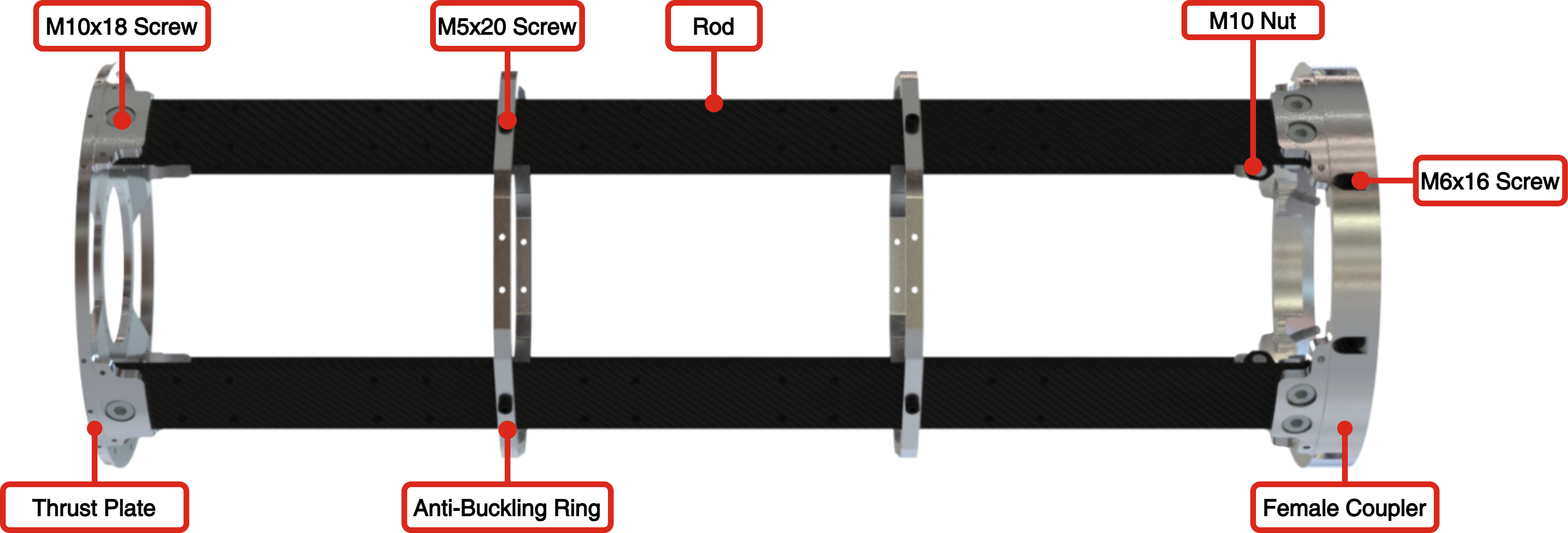
The internal structure is composed of modules identical in composition, but of different length.
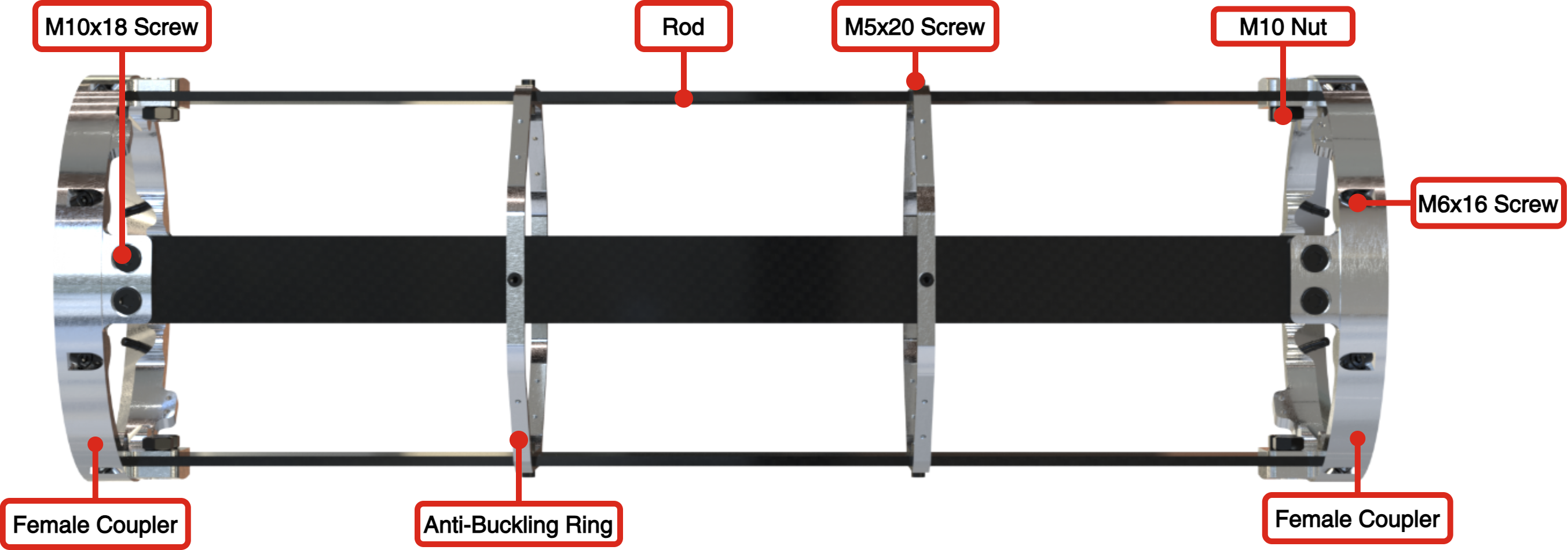
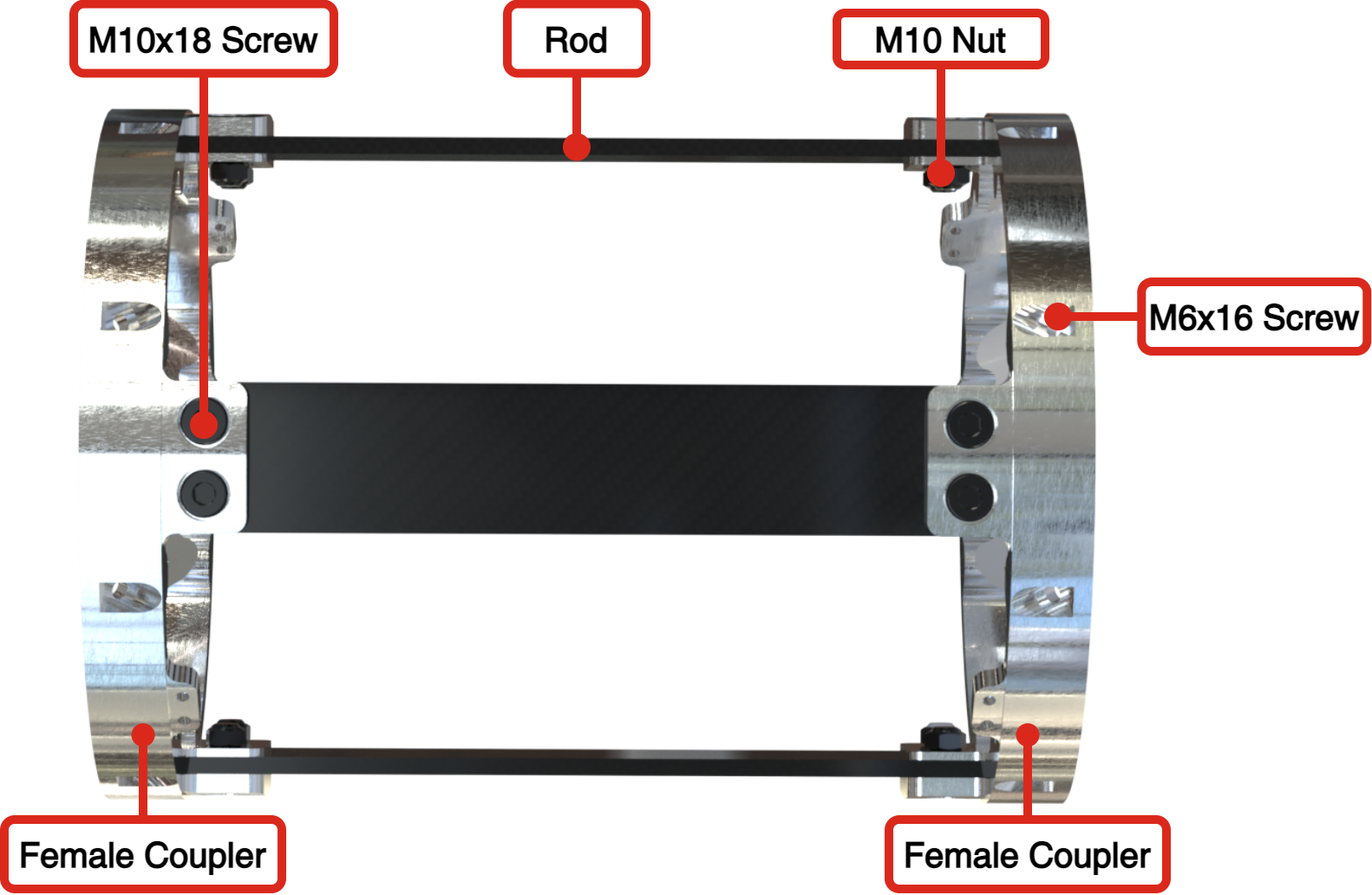
It consists of four CFRP rods distributed so as to respect quadrisymmetry, held on each side by couplers. Anti-buckling rings are distributed throughout the CFRP rods depending on the module length. Fiberglass or carbon fiber panels are then placed on the outside of the modules.
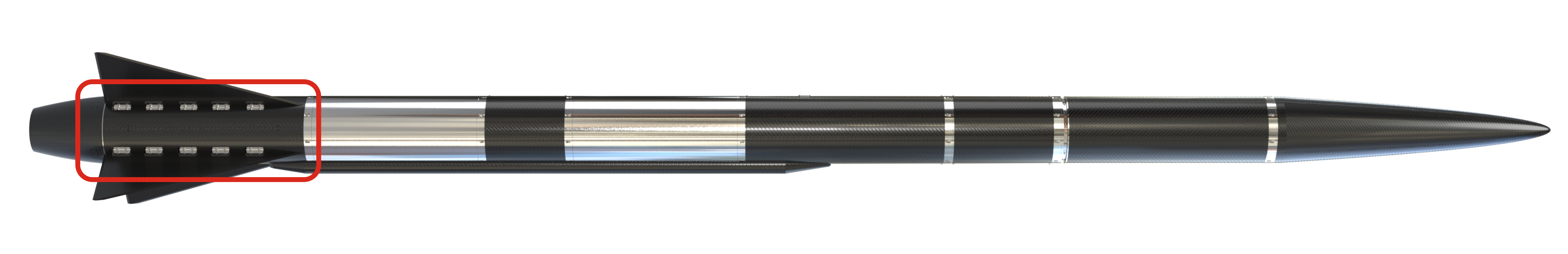
The avionics bay contains the rocket's avionics. It is located between the pressurization bay and the recovery bay. This bay is connected to the parachute, and interfaces with the separation mechanism that releases the parachute after apogee.
| Specification | Value | Unit |
|---|---|---|
| Dimensions | 414 | [mm] |
| Mass | 3595.2 | [g] |
| Design Load (Buckling) | 15000 | [N] |
| Factor of Safety (Buckling) | 2 | |
| Margin of Safety (Buckling) | xxx |
¶ Parts Table
| Part Name | Number of Parts | Main Characteristics | Link to Data Sheet/ DDF |
|---|---|---|---|
| shockpler | x1 | Aluminum CNC manufactured | 2024_C_ST_COUPLERS_DDF |
| Male Coupler | x1 | Aluminum CNC manufactured | 2024_C_ST_COUPLERS_DDF |
| Rod | x4 | Epoxy based CFRP | Next Chapter |
| Anti-buckling ring | X1 | Aluminum CNC manufactured | Next Chapter |
| Ear screw | x16 | M10x18 screw with grade 10.9 | M10_screw_Datasheet |
| Ear nut | x16 | M10 nut with grade 12 | M10_Nut_Datasheet |
| ABR screw | x4 | M5x20 screw with grade 10.9 | M5_screw_datasheet |
| ABR nut | x4 | M5 nut with grade 10 | M5_nut_datasheet |
The pressurant bay contains the pressurization system for the two tanks. This consists of plumbing and a COPV containing the pressurized gas. It is located between the ethanol tank and the avionics bay.
| Specification | Value | Unit |
|---|---|---|
| Dimensions | 754 | [mm] |
| Mass | 3753.3 | [g] |
| Design Load with FoS (Buckling) | 15000 | [N] |
| Factor of Safety (Buckling) | 2 | |
| Theoretical Margin of Safety (Buckling) | 4.42 | |
| Experimental Margin of Safety (Buckling) | 4.59 |
¶ Parts Table
| Part Name | Number of Parts | Main Characteristics | Link to Data Sheet |
|---|---|---|---|
| Female Coupler | x2 | Aluminum CNC manufactured | 2024_C_ST_COUPLERS_DDF |
| Rod | x4 | Epoxy based CFRP | Next chapter |
| Anti-buckling ring | X2 | Aluminum CNC manufactured | Next Chapter |
| Ear screw | x16 | M10x18 screw with grade 10.9 | M10_screw_Datasheet |
| Ear nut | x16 | M10 nut with grade 12 | M10_Nut_Datasheet |
| ABR screw | x8 | M5x20 screw with grade 10.9 | M5_screw_datasheet |
| ABR nut | x8 | M5 nut with grade 10 | M5_nut_datasheet |
| Coupler M6x16 Screw | x16 | M6x17 10.9 low head | M6_screw_datasheet |
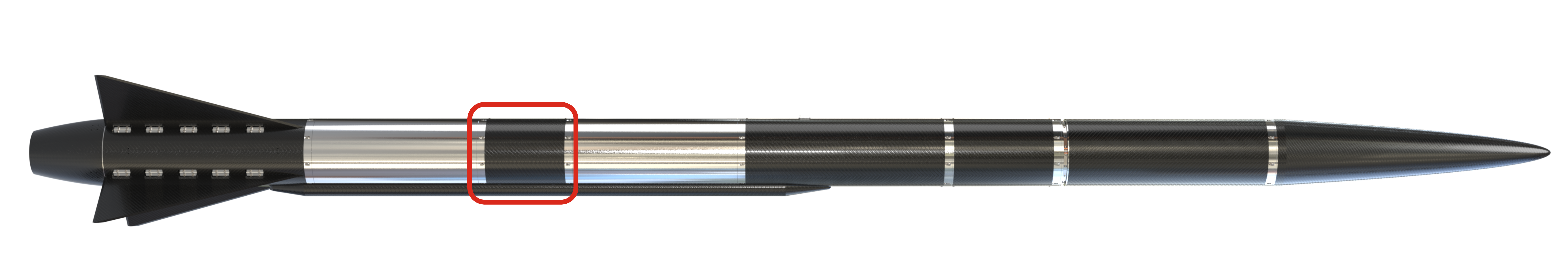
The mid bay contains the plumbing needed to pressurize the liquid oxygen tank and deliver ethanol to the engine. It is located between the Lox tank and the ethanol tank.
| Specification | Value | Unit |
|---|---|---|
| Dimensions | 334 | [mm] |
| Mass | 2380.84 | [g] |
| Design Load with FoS (Buckling) | 15000 | [N] |
| Factor of Safety (Buckling) | 2 | |
| Margin of Safety (Buckling) | xxx |
¶ Parts Table
| Part Name | Number of Parts | Main Characteristics | Link to Data Sheet |
|---|---|---|---|
| Female Coupler | x2 | Aluminum CNC manufactured | 2024_C_ST_COUPLERS_DDF |
| Rod | x4 | Epoxy based CFRP | Next C |
| Anti-buckling ring | none | Aluminum CNC manufactured | - |
| Ear screw | x16 | M10x18 screw with grade 10.9 | M10_screw_Datasheet |
| Ear nut | x16 | M10 nut with grade 12 | M10_Nut_Datasheet |
| Coupler M6x16 Screw | x16 | M6x17 10.9 low head | M6_screw_datasheet |
| ABR screw | None | - | - |
| ABR nut | None | - | - |
The engine bay contains the plumbing leading to the engine and the engine itself. It is located below the LOX tank.
| Specification | Value | Unit |
|---|---|---|
| Dimensions | 738 | [mm] |
| Mass | 3428.3 | [g] |
| Design Load with FoS (Buckling) | 15000 | [N] |
| Factor of Safety (Buckling) | 2 | |
| Margin of Safety (Buckling) | xxx |
¶ Parts Table
| Part Name | Number of Parts | Main Characteristics | Link to Data Sheet |
|---|---|---|---|
| Female Coupler | x1 | Aluminum CNC manufactured | 2024_C_ST_COUPLERS_DDF |
| Thrust Plate | x1 | Aluminum CNC manufactured | 2024_C_ST_THRUST-PLATE_DDF |
| Rod | x4 | Epoxy based CFRP | Next chapter |
| Anti-buckling ring | X2 | Aluminum CNC manufactured | Next Chapter |
| Ear screw | x12 | M10x18 screw with grade 10.9 | M10_screw_Datasheet |
| Ear nut | x12 | M10 nut with grade 12 | M10_Nut_Datasheet |
| ABR screw | x8 | M5x16 screw with grade 10.9 | M5_screw_datasheet |
| ABR nut | x8 | M5 nut with grade 10 | M5_nut_datasheet |
| Coupler M6x16 Screw | x16 | M6x17 10.9 low head | M6_screw_datasheet |
¶ Parts Description
¶ Rods
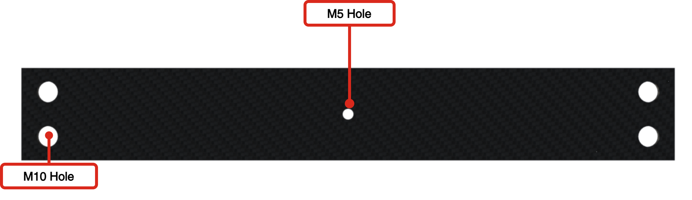
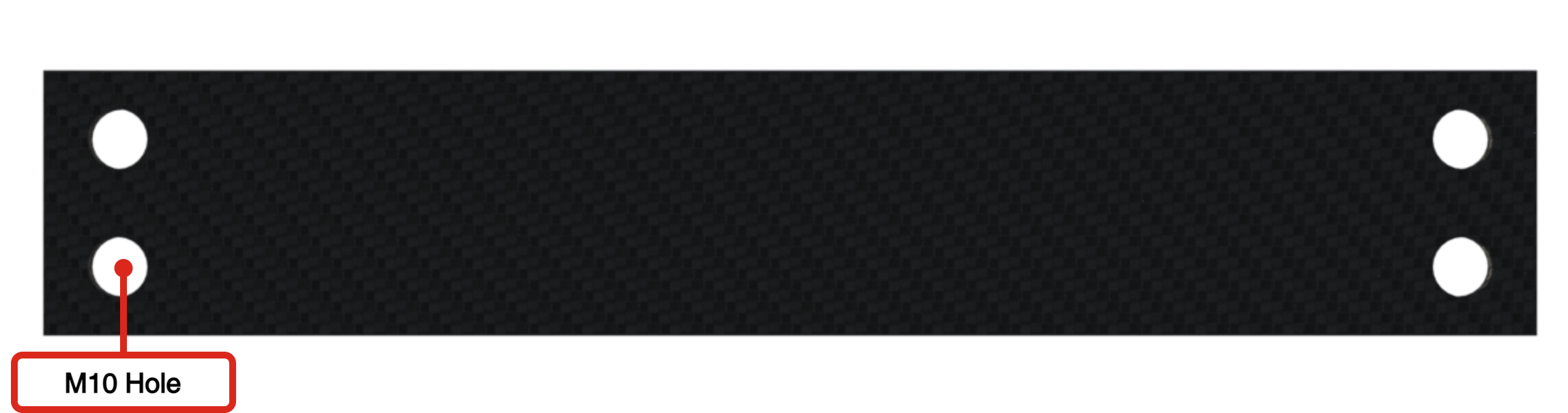
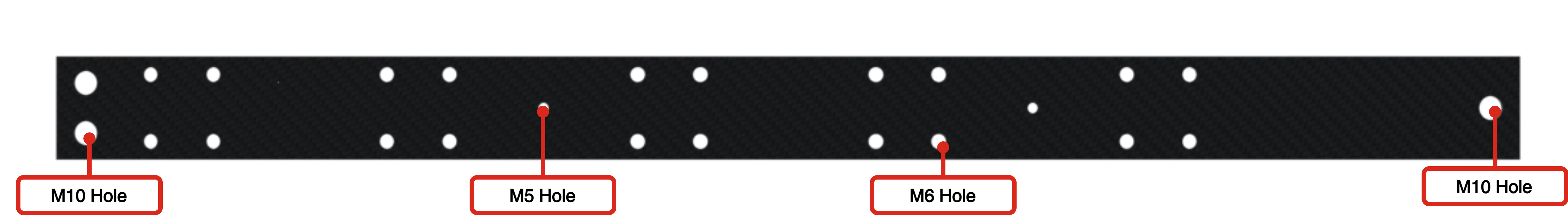
The rods take on all the loads of the rocket and are made of Carbon Fiber Reinforced Polymer (CFRP).
They have a variable length depending on the module. The thickness is defined based on the applied loads c.f 2024_C_ST_ROD_FEA
The width depends on the number of screws and their diameter used in the coupler ears. This dimension must be minimized to allow maximum accessibility within the module for the operators.
¶ Main Specifications
| Specification | Value | Unit |
|---|---|---|
| Number of Parts | 4 | |
| Number of Back ups | 2 | |
| Dimensions | 350 x 50 x 6.09 | [mm] |
| Mass | 186.19 | [g] |
| Manufacturing | 3-axis CNC | |
| Number of M10 hole | 4 | |
| Number of M5 hole | 1 | |
| Design Load with FoS (traction) | 16500 | [N] |
| Factor of Safety (traction) | 2 | |
| Margin of Safety (traction) | 10.479 | |
| Design Load with FoS (Buckling) | 15000 | [N] |
| Factor of Safety (Buckling) | 2 | |
| Margin of Safety (Buckling) | xxx |
| Specification | Value | Unit |
|---|---|---|
| Number of Parts | 4 | |
| Number of Back ups | 2 | |
| Dimensions | 700 x 50 x 6.09 | [mm] |
| Mass | 376.17 | [g] |
| Manufacturing | 3-axis CNC | |
| Number of M10 hole | 4 | |
| Number of M5 hole | 2 | |
| Design Load with FoS(traction) | 16500 | [N] |
| Factor of Safety (traction) | 2 | |
| Margin of Safety (traction) | 10.479 | |
| Design Load with FoS (Buckling) | 15000 | [N] |
| Factor of Safety (Buckling) | 2 | |
| Margin of Safety (Buckling) | xxx |
| Specification | Value | Unit |
|---|---|---|
| Number of Parts | 4 | |
| Number of Back ups | 2 | |
| Dimensions | 280 x 50 x 6.09 | [mm] |
| Mass | 148.13 | [g] |
| Manufacturing | 3-axis CNC | |
| Number of M10 hole | 4 | |
| Number of M5 hole | - | |
| Design Load with FoS (traction) | 16500 | [N] |
| Factor of Safety (traction) | 2 | |
| Margin of Safety (traction) | 10.479 | |
| Design Load with FoS (Buckling) | 15000 | [N] |
| Factor of Safety (Buckling) | 2 | |
| Margin of Safety (Buckling) | xxx |
| Specification | Value | Unit |
|---|---|---|
| Number of Parts | 4 | |
| Number of Back ups | 2 | |
| Dimensions | 700 x 50 x 6.09 | [mm] |
| Mass | 369.76 | [g] |
| Manufacturing | 3-axis CNC | |
| Number of M10 hole | 3 | |
| Number of M5 hole | 2 | |
| Number of M6 hole | 20 | |
| Design Load with FoS (traction) | 16500 | [N] |
| Factor of Safety (traction) | 2 | |
| Margin of Safety (traction) | 10.479 | |
| Design Load with FoS (Buckling) | 15000 | [N] |
| Factor of Safety (Buckling) | 2 | |
| Margin of Safety (Buckling) | xxx |
¶ Analysis and Simulations
The rods were simulated in traction with a load equivalent to parachute deployment for Firehorn II with full tanks. The rods were then simulated in buckling mode, corresponding to engine thrust.
Axial traction
¶ Technical Drawings
Firstly, twelve 1200 [mm] long rods with screws hole at both ends were cut using a 3-axis CNC, as the final length was not yet known. This first cut out was done by APCO Technology.
Then, once the length had been defined, the rods were cut to the right length using a 3-axis CNC from EPFL.
For more information about the rods manufacturing, refer to :
¶ Ears
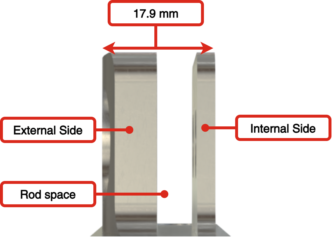
The ears are present on the couplers and are used to clamp the rods as shown in the image.
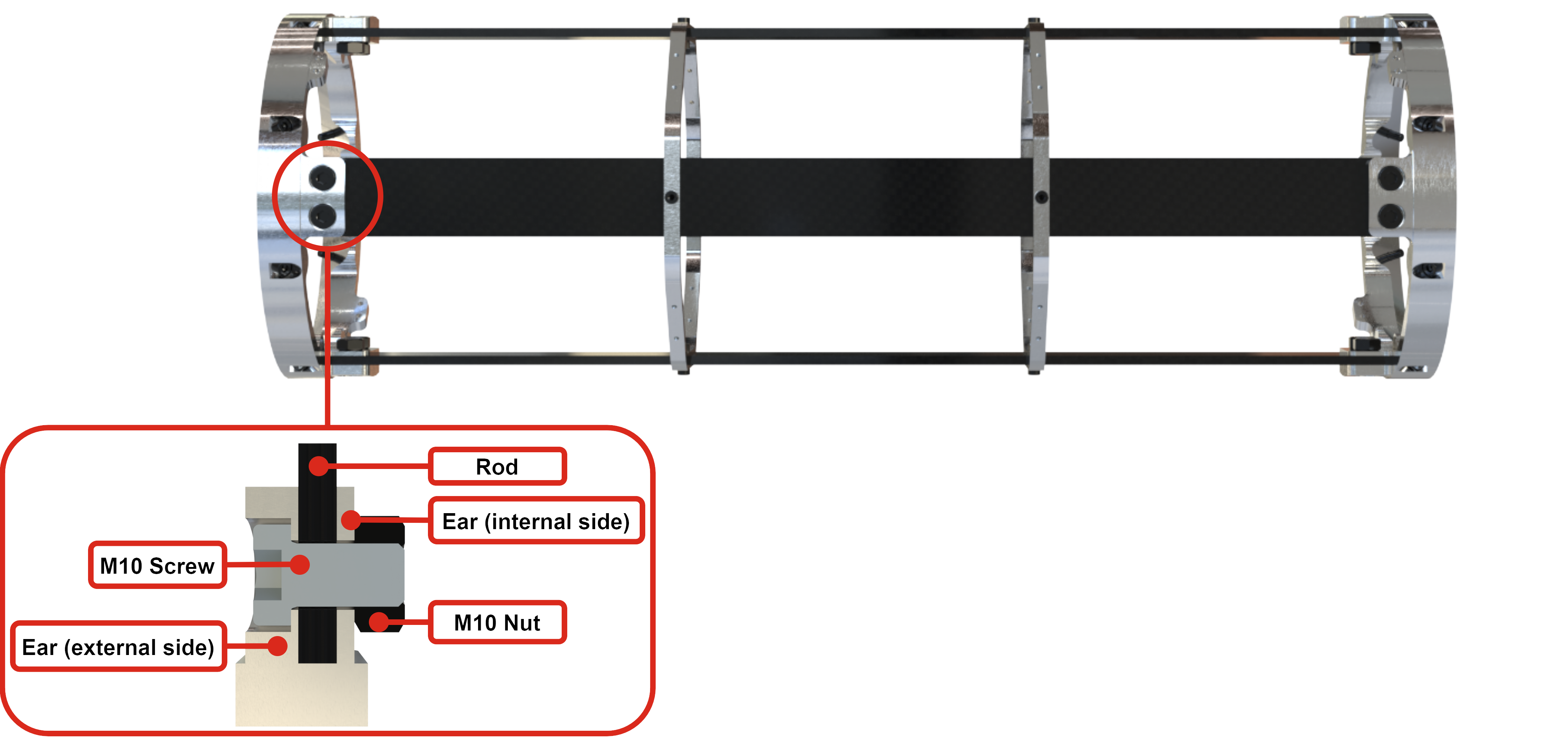
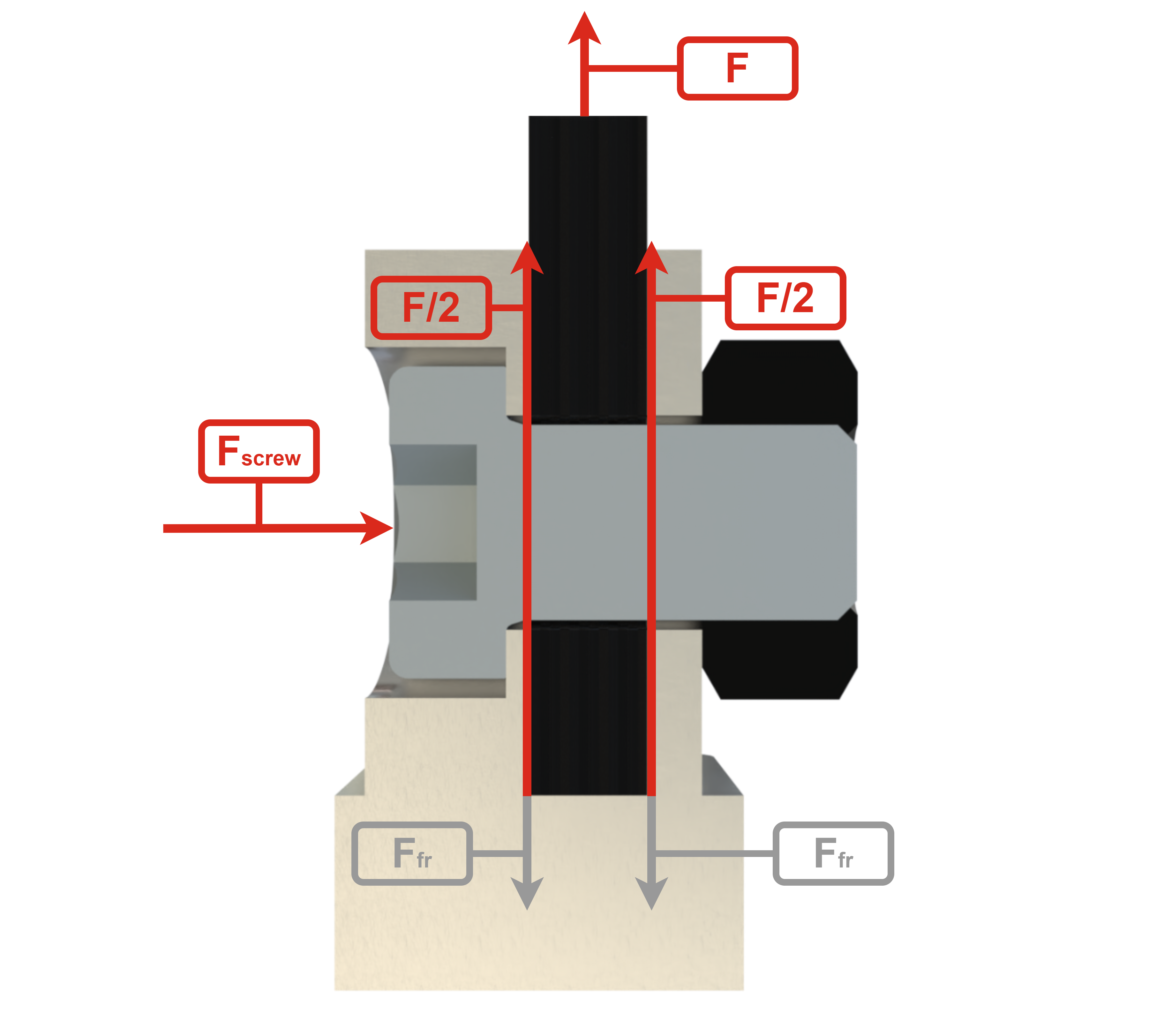
The rods are held exclusively by friction, the screws are only here to apply pression between the ears and the rods. It is therefore necessary to design them according to the forces applied to the rods. In addition, the type of screw also depends on sizing constraints. In fact, the screw must be between the internal diameter of 240mm and the integration diameter of 188mm. It must have sufficient thread for the nut, and its screw head must be inside the outer part of the ear.
To comply with these constraints, the maximum screw size is M10x18 low head.
To determine the screw's grade and ensure it can withstand flight loads. It is necessary to calculate the maximum torque and total stress.
Knowing that the traction force of 30 g is the most important constraint that will be applied, we can calculate the normal force needed to maintain the rods by friction. The approximate dry mass of the 30 [km] launch vehicle of 220 [kg] is used for this load case.
Since both surfaces of the rods are in contact with the aluminum, the normal force that must be applied on the rod is:
Then, the normal force per screw is:
Using the ERT Screw dimensioning we obtain :
Screw caracteristic :
Type of screw : M10x18 low head
Torque: 45 [Nm]
Total constraint: 606.7 [MPa]
To withstand this torque and respect the geometric constraints, the right screw is a class 10.9 M10x18 low head screw.
Following tensile tests to validate the choice of screws, the results showed that 70 Nm of torque was required instead of 45 Nm. For more information on the results, please refer to the following document:
2024_C_ST_INTERNAL-STRUCTURE-SCREWS_TR
Screw Caracteristic :
Type of screw : M10x18 low head
Grade : 10.9
Torque: 70 [Nm]
Total constraint: 606.7 [MPa]
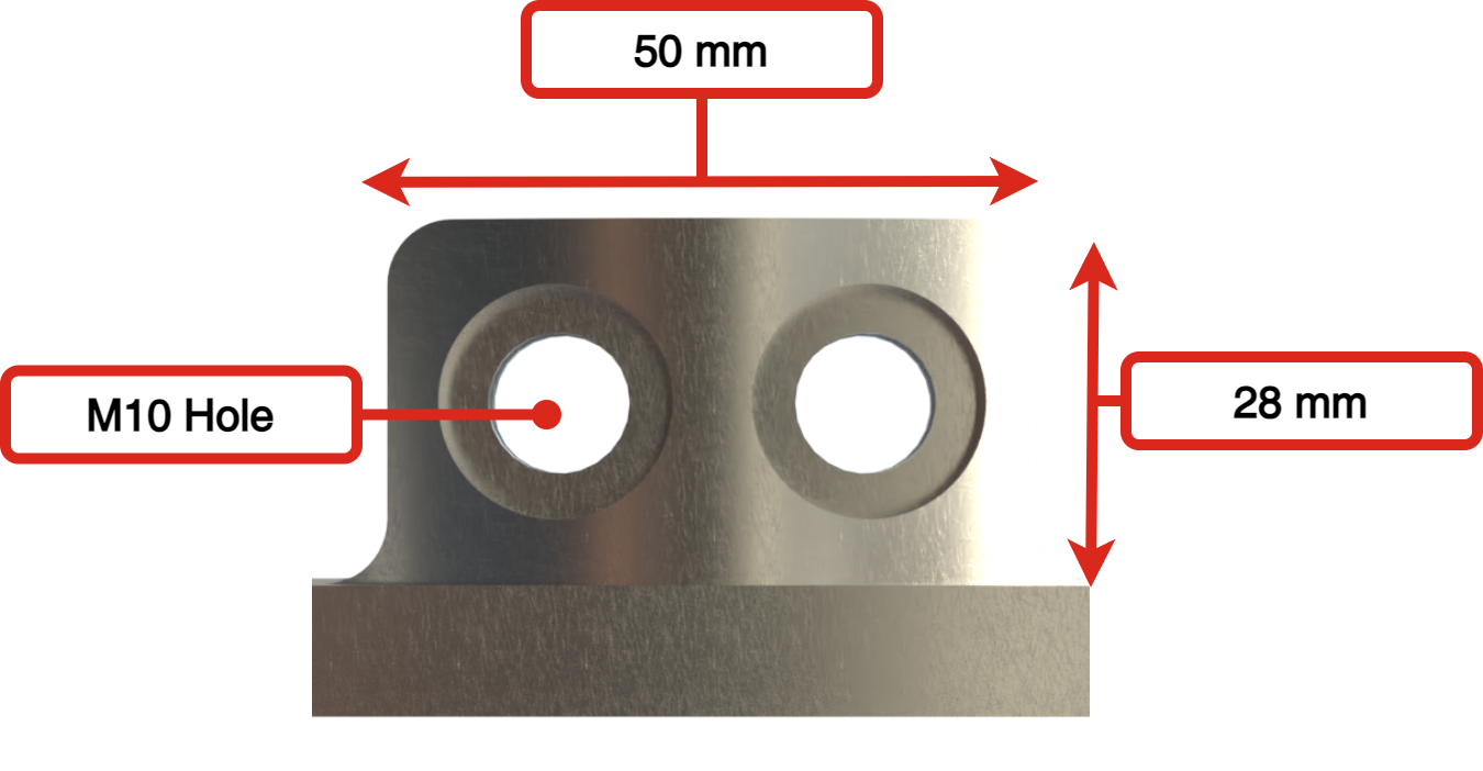
¶ Main Specifications
To ensure optimal clamping of the rods, the ear are only manufactured after the carbon rods have been produced. Indeed, the difference between the theoretical and actual rod thickness is on the order of a tenth of a millimeter. Therefore, to achieve the best possible clamping, the rods must first be produced and measured to calculate their average thickness. This measurement is then used to adjust the spacing in the ear before manufacturing the mechanical parts.
 |
 |
|---|
| Specification | Value | Unit |
|---|---|---|
| Number of Ears (per part) | 4 | |
| Dimensions | 28 x 17.9 x 50 | [mm] |
| Manufacturing | 5-axis CNC | |
| Design Load with FoS (traction) | 16500 | [N] |
| Factor of Safety (traction) | 2 | |
| Margin of Safety (traction) | 0.01 |
¶ Possible Improvements
There are several improvements that could be made to this clamping system. Firstly, it would be beneficial to increase the coefficient of friction between carbon and aluminum. This can be achieved either by machining the mechanical part, or by adding a coating between the two components. Although gluing the parts together has been considered, this goes against the modular spirit of this design, which requires quick and easy assembly/disassembly.
Secondly, to ensure a more optimal grip on the rod, the ear could be sized according to the thinnest rod, then the excess material (on the order of a tenth of a millimeter) could be milled off on the thicker rods. This would provide a better contact surface between the parts.
Thirdly, by reducing the coefficient of friction between screw head and lug, screw and nut, and nut and lug, tightening force could be increased at lower torque.
Finally, by further refining the design of the ear with pins, we could reduce the torque required and offer greater flexibility in modifying the finish of the inner surface. It might even be possible to machine small teeth that dig into the carbon to reduce slippage. For further details, please see the attached documents :
¶ Coupler
The main function of couplers is to assemble the various modules of the Firehorn rocket. An outside screwing coupling system with a conical interface (called radax) was chosen to meet operations & interfaces flexibility needs.
For more informations :
¶ Antibuckling Ring
The anti-buckling rings are designed to prevent the CFRP rods from buckling during the launch. They will be strategically distributed along the length of the rods.
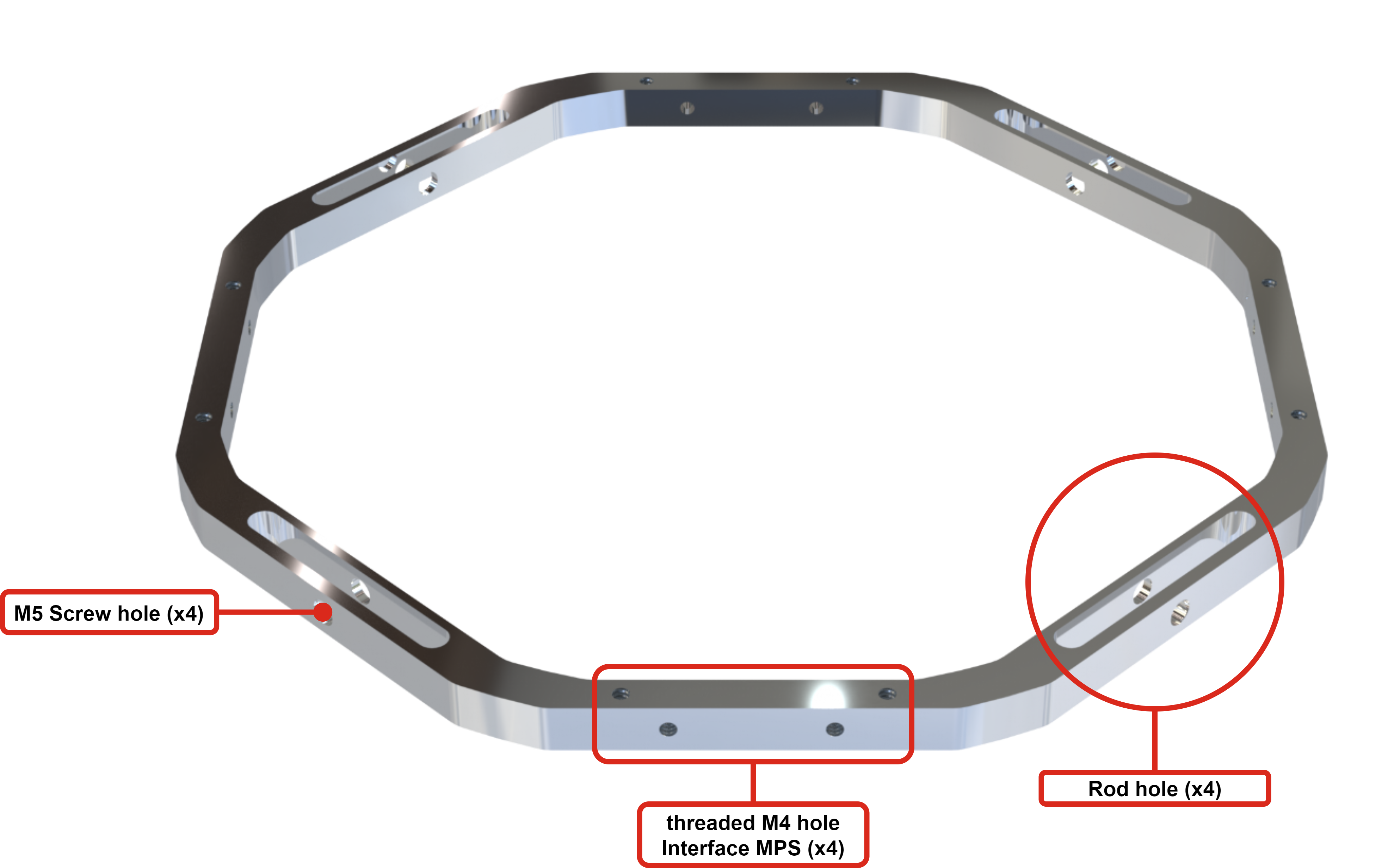
A secondary function of the ABR is to allow any modular parts system designed by the propulsion team to be attached to it. Two different interfaces are available, one on the top and one on the outside of each quarter.
The geometry of the ABRs was determined using linear buckling simulation. The design was optimized so that the first buckling mode of the ABR was slightly higher than that of the rods.
The most critical axial load (in the direction of the rocket) exerted on one of the ABRs is the mass of the COPV in the pressurant bay. This load is used to size and select the screws enabling the ABR to be attached to the rods. For ease of production, all ABRs are dimensioned according to the critical load, even if it is exerted on a specific ABR.
According to the requirement on traction load, the normal load required to hold the ABR in position is calculated as follows :
- Friction coefficient :
- Nomber of surfaces :
- Nomber of rods :
- COPV full mass :
Using the ERT Screw dimensioning we obtain :
Per screw :
Torque 1.35 [Nm]
Total constraint 291 [MPa]
Such values would allow the use of an grade 8.8 M4 screw.
However, as there was a lot of uncertainty about the type of MPS that would be attached to the ABRs, it was decided to take a larger safety margin and use M5 screws in quality grade 10.9 instead and apply the maximum torque allowed by the screw, which is :
Torque 9 [MPa]
Total constraint 916 [MPa]
These values correspond to a factor of 5 on the COPV force of 2559 [N].
Screw Caracteristic :
Type of screw : M5x20
Grade : 10.9
Torque: 9 [Nm]
Total constraint: 916 [MPa]
¶ Technical Drawings
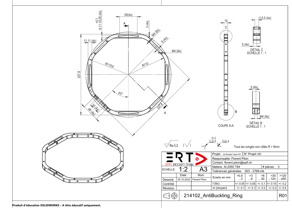
¶ Main Specifications
| Specification | Value | Unit |
|---|---|---|
| Number of Part | 5 | |
| Mass | 151.75 | [g] |
| Design Load with FoS | 15000 Axial | [N] |
| Factor of Safety | 2 | |
| Margin of Safety | 1.42 | |
| Manufacturing | 5-axis CNC | |
| Cost | 136 | [CHF] |
¶ Analysis and Simulations
¶ Possible Improvements
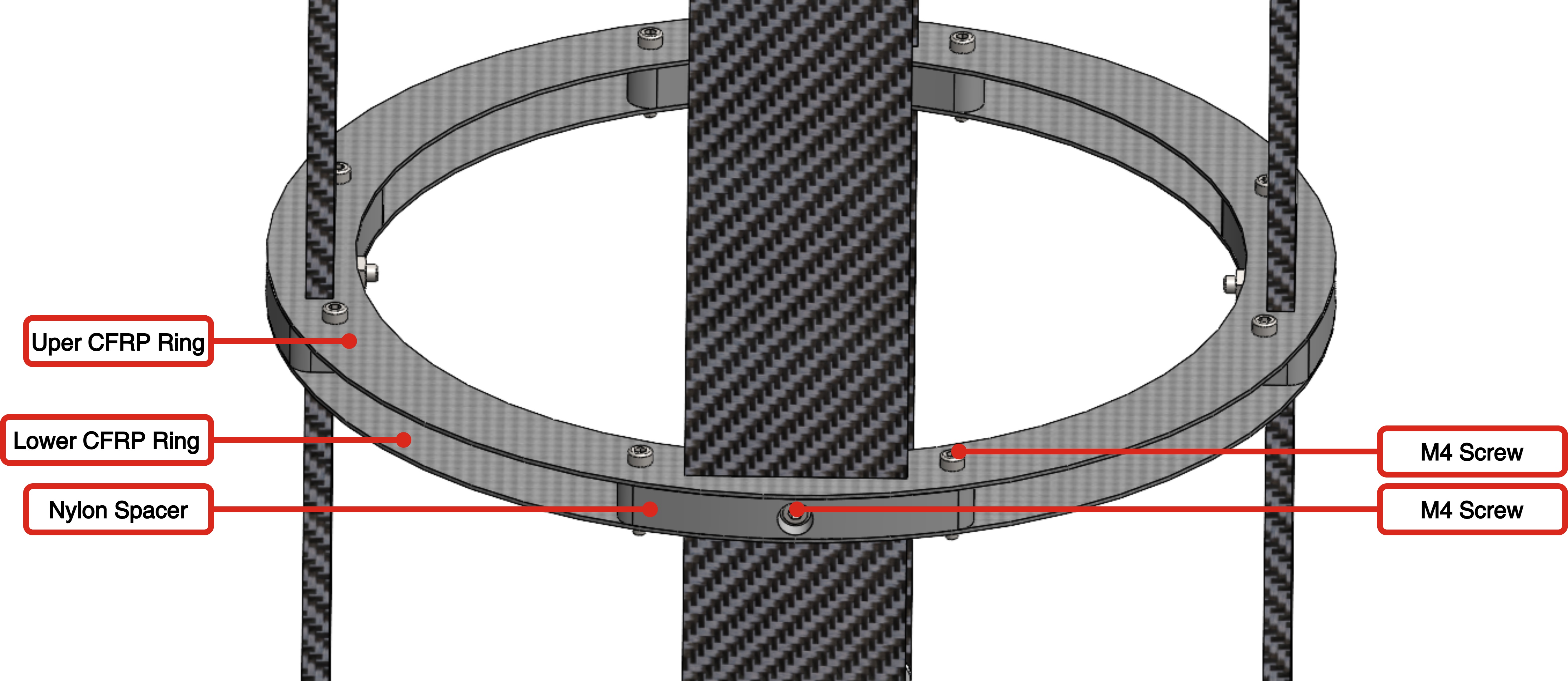
One potential improvement would be to change both the materials and the design in order to maintain performance while reducing weight. A concept was considered in which the ABR would consist of two carbon plates separated by 3D-printed nylon spacers. This configuration could potentially halve the mass of the ABR and allow for different spacers depending on specific needs. It would also make it possible to place MPS units in various quadrants. However, this design was set aside due to time constraints that prevented deeper investigation and load-capacity testing.
¶ Interfaces
The internal structure interfaces with several assemblies and subsystems.
¶ Interfaces with others structure assemblies
The internal structure interfaces with the rocket fins. The fins are held in place by aluminum brackets that are screwed onto the engine bay rods. These rods have through-holes for the bracket screws, and the brackets are then secured to the rods using a bolted assembly.
For more information on the fins attachment and interfaces, please refer to the following document:
The internal structure also interfaces with one of the rail buttons. In fact, one of the two rail buttons is attached to a Modular Part System (MPS) in segment 5, quarter 1 of the rocket. These MPS parts are crimped around the carbon rods. They require no drilling into the carbon rods, and can be added, removed and moved simply.
For more information on the rail button attachment and interfaces, please refer to the following document :
¶ Interfaces with Propulsion sub-system
The propulsion subsystem uses the ABRs and rods to position the various MPS components they need. They make use of the quarter interfaces (M4 holes) on the ABRs in both the Engine Bay and the Pressurant Bay. In the Engine Bay, Mid Bay, and Pressurant Bay, additional MPS components are mounted directly onto the carbon rods whenever the nearest ABR interface is unavailable.
For more information on the interfaces, please refer to the following document :
- [🔗 ST/PR Low Level Interface Management (LLIM)]The Low Level Interface Management beetween ST and PR
¶ Interfaces with Payload sub-system
The Payload subsystem uses MPS attached to the rods to position their cameras. One MPS is placed in the engine bay and the second in the Pressurant Bay.
For more information on the interfaces, please refer to the following document :
- 🔗 ST/PL Low Level Interface Management (LLIM) The Low Level Interface Management beetween ST and PL
¶ Conception Flux Diagram
The following steps were taken to dimension the internal structure:
- Computational analysis of the tensile load case to determine the type and number of screws. (chapter "Ear" of this document)
- Selection of screw length based on internal diameter and integration diameter constraints.(chapter "Ear" of this document)
- Ear dimmensioning according to screw selection.(chapter "Ear" of this document)
- Rod width is determined according to ear and screw type/number.
- Rod length is determined by the space required for other subsystems.
- Rod thickness is determined according to the compression load case.
c.f 2024_C_ST_ROD_FEA
Rods must be produced before the mechanical parts, as the space inside the ear depends on the actual thickness of the rods, not the theoretical thickness.
c.f2024_C_ST_CFRP-PLATE_MAP
- Tensile tests are carried out to verify the rods' resistance to load and to check the sizing of the screws.
- Linear buckling simulations are then carried out to size and design the anti-buckling rings. These simulations are also used to determine the number of ABR required per module.
- Non-linear buckling simulations are performed to check all modules.
- Buckling tests are performed to qualify and validate the structure.
Below is a diagram summarizing the design stages of the internal structure.
¶ Function Tree
Below is a diagram summarizing the function of the internal structure
¶ Function Table
| Function | Part(s) involved | Interfaces | Performance Requirements |
|---|---|---|---|
| Ensure the structural integrity of LV | Coupler, Rods, ABRs | Other modules and subsystems | FEA |
| Maintain all the subsystems together | Couplers, Rods, ABRs | Other modules, MPS | Couplers to fix the modules together, interface on the ABRs |
| Withstand the loads applied to the LV | Coupler, Rods, ABRs | Other modules, fins | FEA |
| Provide fixation points for other subsystems | ABRs | MPS | MPS interface on the ABRs. |
| Provide fixation points for rail buttons | ABRs | Rail buttons | Rail buttons fixations on the ABRs. |
| Provide fixation points for the fins | Rods | Fins | Fins fixations on the rods of the engine bay. |
| Withstand traction loads | Coupler, Rods | FEA | |
| Withstand compression loads | Coupler, Rods | FEA | |
| Withstand bending loads | Coupler, Rods | Fins | FEA |
| Avoid buckling | ABRs, Rods | FEA |
¶ Technical Budget, Margins and Deviation
¶ Engine Bay
| Type of value | Units | Requirement Value | Actual Value | Deviation |
|---|---|---|---|---|
| Total Weight | g | 7000 | 3428.3 | - 52 % |
| Total Length | mm | 700 +/- 20 | 738 | + 2.5 % |
¶ Mid Bay
| Type of value | Units | Requirement Value | Actual Value | Deviation |
|---|---|---|---|---|
| Total Weight | g | 3800 | 2380.84 | - 37 % |
| Total Length | mm | 280 | 334 | + 19 % |
¶ Pressurant Bay
| Type of value | Units | Requirement Value | Actual Value | Deviation |
|---|---|---|---|---|
| Total Weight | g | 6000 | 3753.3 | - 37.5 % |
| Total Length | mm | 700 | 754 | + 7 % |
¶ Avionics Bay
| Type of value | Units | Requirement Value | Actual Value | Deviation |
|---|---|---|---|---|
| Total Weight | g | 4000 | 3595.2 | -10.1 % |
| Total Length | mm | 350 | 414 | + 18 % |
¶ Design Constraints
¶ Constraints for Production
The clamping system for the rods using ears requires a specific order for the production of the parts. The ears are designed based on the thickness of the rods, with strict tolerances to ensure a proper fit. However, the real thickness of the rods may differ from the theoretical value because it is challenging to precisely quantify the effects of compaction and the absorption of excess resin during the curing process. Therefore, it is crucial to first manufacture the rods to determine an average thickness, which will then be used to size the ears before starting production of the couplers and the antibuckling rings.