¶ Introduction
Firehorn coupling systems were designed during a semester project and its process is extensively detailed in its associated semester project report, new modifications, however, are also presented throughout this document.
¶ Definitions and Abbreviations
- CPLR: Coupler
- CFRP: Carbon Fiber Reinforced Polymer
- Li: Length of thread engagement
- Lk: Screw free length (distance between screw head base and engaged threads)
- FoS: Factor of Safety
¶ Applicable and Reference Documents
¶ Requirements
- 2024_C_SE_ST_COUPLER_REQ_01 Coupler declaration of purpose
The Coupler shall structuraly connect two distinct parts of the LV. - 2024_C_SE_ST_COUPLER_REQ_02 Outside coupling
The Coupler shall be assembled without accessing the inside of the LV. - 2024_C_SE_ST_COUPLER_REQ_03 Compatibility with the internal structure
The Coupler shall be compatible with the LV architecture (e.g. use of non structural panels as fairing & CFRP rods as structural elements) and other interfaces. - 2024_C_SE_ST_COUPLER_REQ_04 Compatibility with nearby temperatures
The Coupler shall accommodate thermal stresses & unscrewing phenomenon due to neighbouring temperatures as low as [-180]°C. - 2024_C_SE_ST_COUPLER_REQ_05 Mass
The whole Coupler's assembly shall weigh less than [1200]g. - 2024_C_SE_ST_COUPLER_REQ_06 Integration diameter
The Coupler's integration diameter, usable for the passage of modules, shall be at least [188]mm. - 2024_C_SE_ST_COUPLER_REQ_09 Integration time
The time needed to assemble 2 Coupler with eachother shall be less than [3]min. - 2024_C_SE_ST_COUPLER_REQ_11 Tools required for assembly
Assembly of the Coupler should only require common tools. - 2024_C_SE_ST_COUPLER_REQ_13 Post-assembly angular alignment
The circular angular difference between two structural rods on either end of a Coupler pair shall be less than [1]° after assembly. - 2024_C_SE_ST_COUPLER_REQ_14 Wear and fatigue
The Coupler shall withstand between [100-1000] assembly/disassembly cycles while remaining operational. - 2024_C_SE_ST_COUPLER_REQ_15 Assembly steadiness
Both ends of the Coupler shall not rotate relative to each other during assembly. - 2024_C_SE_ST_COUPLER_REQ_17 Ease of machining
The Coupler parts shall be machined with conventional machining processes in EPFL workshops (e.g. ATME) using standard procedures. - 2024_C_SE_ST_COUPLER_REQ_18 Impermeability
The Coupler shall be IP54 compliant. - 2024_C_SE_ST_COUPLER_REQ_19 Coupler load case - traction
The Coupler shall withstand [132000]N of tensile loads. - 2024_C_SE_ST_COUPLER_REQ_20 Coupler load case - compression
The Coupler shall withstand [15000]N of compression loads. - 2024_C_SE_ST_COUPLER_REQ_21 Coupler load case - bending
The Coupler shall withstand [7500]Nm of bending moment.
¶ Functional Description
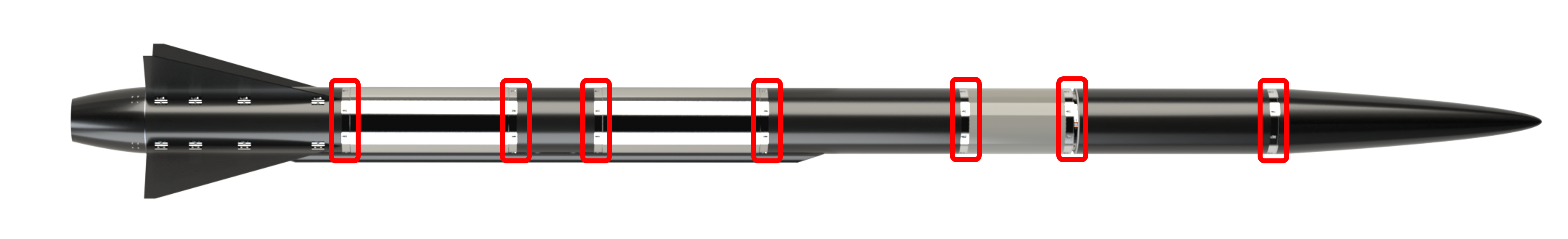
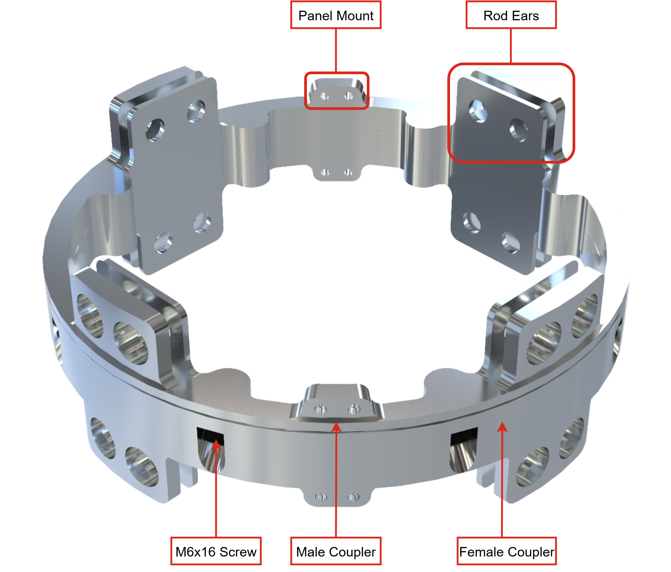
The main function of couplers is to assemble the various modules of the Firehorn rocket. For this purpose, it should be compliant with the structural rods architecture. In addition, it has to accommodate panel mounts to fix the airframe panels. In parallel to achieving these functions, the goal was to design couplers that can be easily adapted to future larger rockets, by being scalable and by providing flexibility for operations and interfaces (i.e. can also be used with previous rockets architectures such as couplers glued in CFRP tubes). The reference coupling system of Firehorn rocket is presented below: it is used when two modules with rods architecture and panels must be assembled. From this reference (standard) system, many interfaces driven versions were adapted (see Interfaces section).
¶ Physical Architecture
An outside screwing coupling system with a conical interface (called radax) was chosen to meet operations & interfaces flexibility needs. The initial versions presented in the PDS (Sect. 8) were subject to a few modifications detailed in its design justification file, in which 3 design options were still being considered. In the absence of no-go from external reviewers between all options, it was decided by the ERT board to go for the 45° option without short centering option as it should provide the lowest coaxiality defect.
In addition to this choice, requirements 05 to 08 were subject to changes (see DJF)
- Mass allowed increased from 1000g to 1200g
- Integration diameter increased from 160mm to 188mm
- FoS of mechanical axial loads reduced from 3 to 2
- Mechanical bending loads reduced from 9000Nm to 7500Nm
Further design changes are summarized below, as well as associated design considerations:
- External diameter increased from 202mm to 242mm (rocket-wide update from system engineering to mitigate flight stability issues)
- 8 M5x16 10.9 screws were not sufficient anymore to withstand the traction load (REQ_07) with the updated requirements and the 45°C interface. 8 M6x16 10.9 screws was the preferred option instead of 16 M5x16 8.8 screws as it would at least double the assembly time and complexify assembly operations (and also manufacturing). Additionally, it could not provide a uniformely distributed pattern of screws around the vertical axis without having some screws under ears.
- Material: now Al 2050-T84 (Al 6082-T6 previously)
- M6 screws head should be flushed inside (previously 1-2mm outside)
- For non-glued couplers, it was highlighted by ATME the minimum thickness between internal and external diameters should be at least 10mm.
- Ears design were provided by internal structure.
- Assembly height and internal diameter are optimized by the screw type to answer mechanical loads requirements [RD02] (Appendix 1)
- A cut called "flower" pattern was performed to reduce mass using the previous criterion.
- Panels mounts (8.5mm thick) for M4x10 screws with Li = 1D = 4mm Lk = 1.5D = 6mm to prevent as much as possible unscrewing by vibrations induced on the outer panels.
- All fillets (congés) were set to 5mm to simplify manufacturing operations.
Finally, the reference coupling system is presented below.
¶ Characteristics
- Material: Al 2050-T84
- External diameter: 243mm
- Internal diameter: 195mm
- Assembly height without ears: 32mm
- Ears: 2 M10x18 10.9 low head with nuts for 6.11mm thick rods
- Panel mounts: 4 M4x10 8.8 screws (2x2 arrangement) for each coupler
– Lk = 6mm > 1D
– Li = 4mm = 1D- Coupling screws: 45° pattern between each (22.5° away from ears midplane) with a 45° conical coupling surface (see below)
– 8 M6x16 10.9 low head (DIN 6912)
– Li = 1.5D = 9mm (use of HELICOIL® thread inserts, not shown on the image above)
– Lk = 1D = 6mm
– Required drill depth is 14.1mm to set thread inserts.
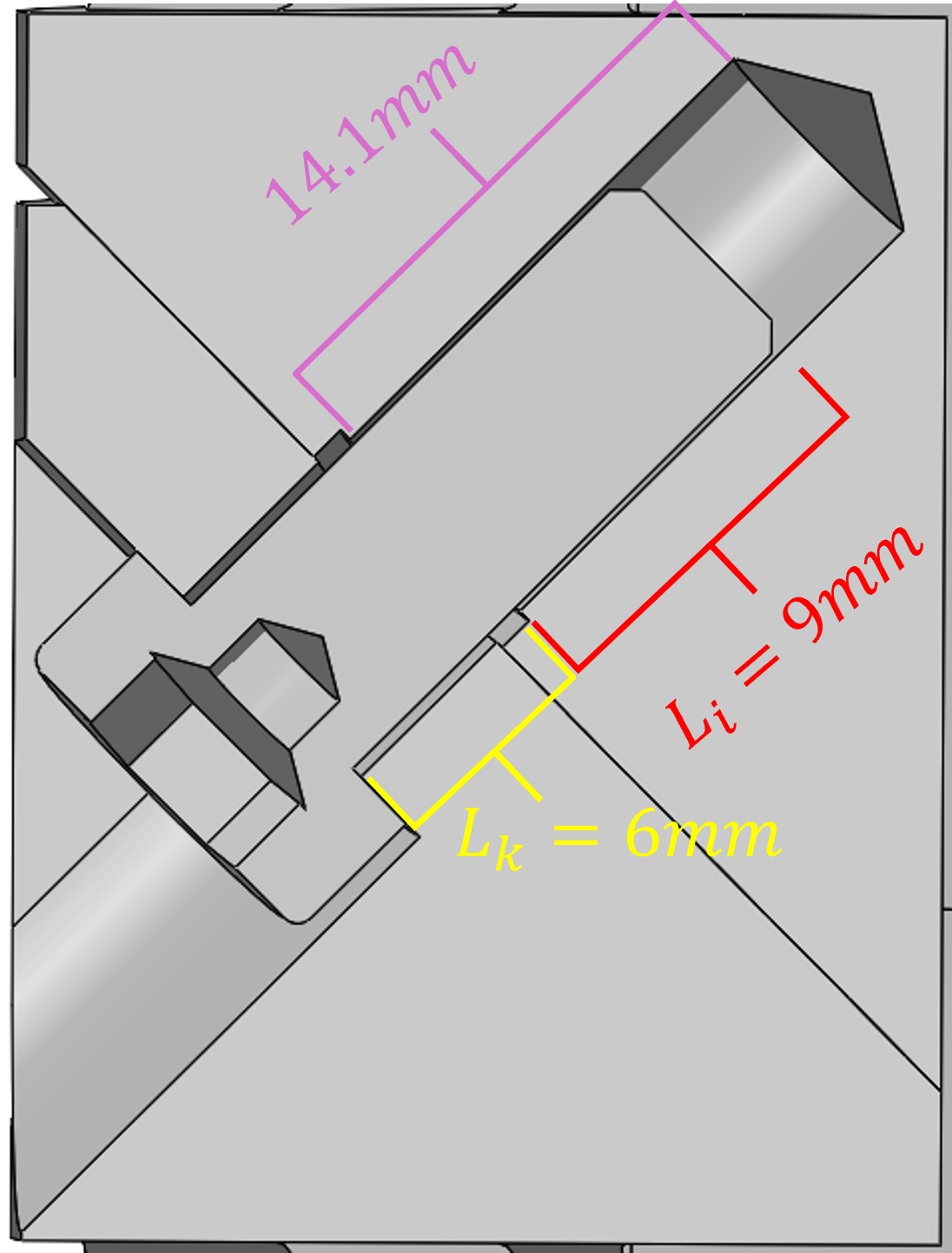
Screw plus tapping being the best way to secure bolted assemblies (especially compared to screw plus nut), the use of screw thread inserts (HELICOIL®) was considered. Yet, as one deals with aluminum parts, it is necessary to use these helical inserts to prevent damage to the aluminium tapping (seizing) since more than 100 screwing/unscrewing cycles are planned (test assemblies). In addition, it better distributes the loads along the threads & reduces thread friction, which in fine requires a lower torque for a given preload.
- Screw preload (here, 70% of expected load) for the M6 screws was determined using the semester project's MatLab script (see first paragraph of this document), with modifications according to M6 screw characteristics instead of M5. This, in turn, allowed for the tightening torque to be determined for each M6 screw.
The exact value comes out at 3.76 N.m with a FoS of more than 1.75. This is coherent and aligns with predictions made in WM17. For additional safety, all M6 screws will be tightened beyond this torque.- Previous concerns were expressed as to whether the shape of the holes on the radax setup would allowed for torque tightening. This was checked and dismissed after real-life testing that demonstrated no apparent issue while torque tightening the M6 screws.
¶ Parts Tree
¶ COTS Parts Table
| Part Name | Number of Parts | Main Characteristics | Link to Data Sheet |
|---|---|---|---|
| 214203_screw_M6x16_10.9 | x8 (per assembly) | M6x16 10.9 low head (DIN 6912) | Norelem |
| HELICOIL DIN 6912 | x8 (per assembly) | HELICOIL® Plus Free Running M6X1.5D Inox | Bricovis |
| HELICOIL Tap | x1 (per rocket) | Taraud Machine Trous Débouchants pour HELICOIL® M6 | Bricovis |
| HELICOIL Installation tool | x1 (per rocket) | Appareil de Pose HELICOIL® avec Nez de Guidage Type 01 M6 | Bricovis |
| 214204_screw_M4x12_10.9 | x8 (per assembly) | M4x12 10.9 Rounded head, hex socket | Norelem |
¶ SRAD Parts Description
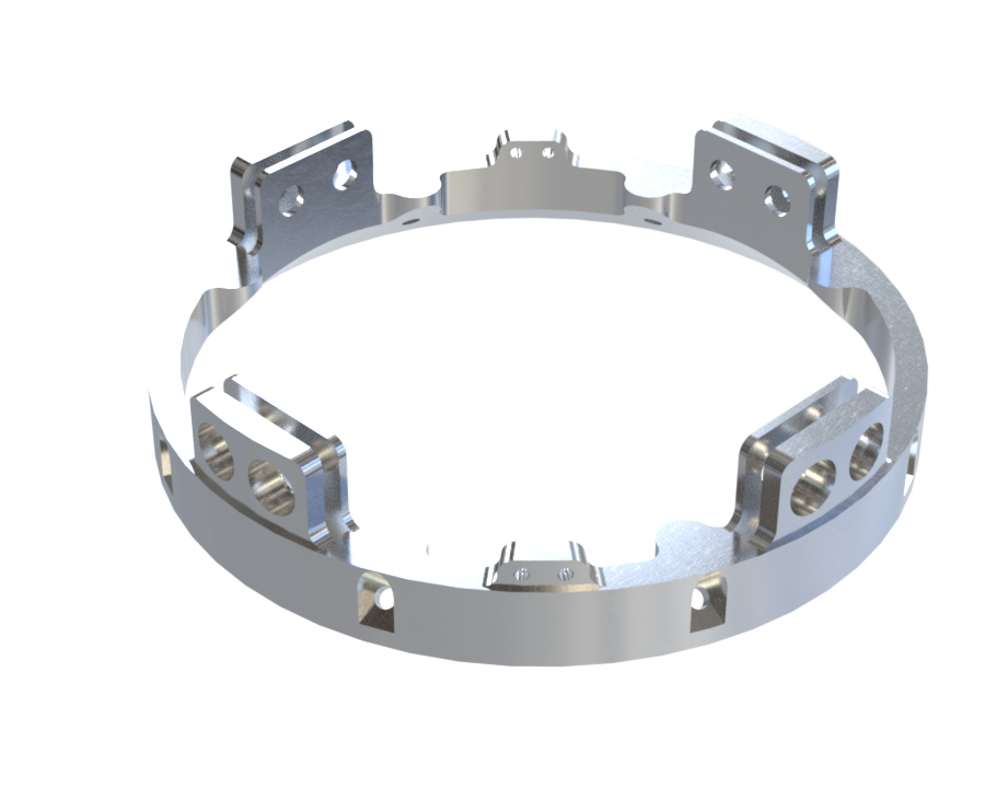
The reference coupling system is made of two parts: the female coupler and the male coupler. These two parts have various iterations based on the requirements needing to be met between different interfaces, as described below.
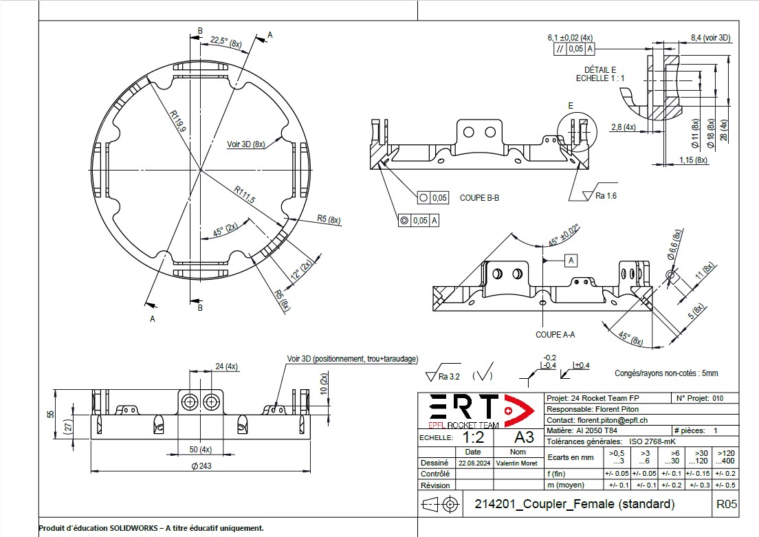
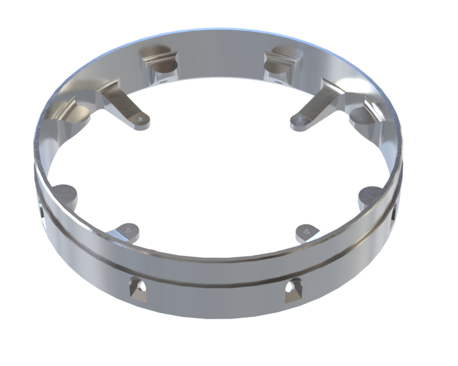
¶ 214201_Coupler_Female
Standard female coupler. In this design we find:
- 4x standard ears (to be screwed using M10 screws to clamp 4 rods);
- 2x smaller cover ears (M4 screws);
- 8x 45 degree extrusions that have been discussed above in this document. These will not be mentionned in the iterations below (M6 screws).
¶ Description
| Part Name | Number of Parts | Main Characteristics | Link to .SLDPRT file |
|---|---|---|---|
| 214201_Coupler_Female | x1 | Din = 195mm, Dout =243mm, height=55m, m=695g, standard configuration (a) | 214201_Coupler_Female.SLDPRT |
¶ Technical Drawing
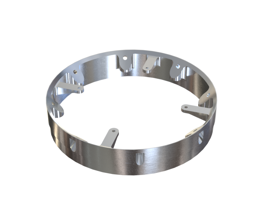
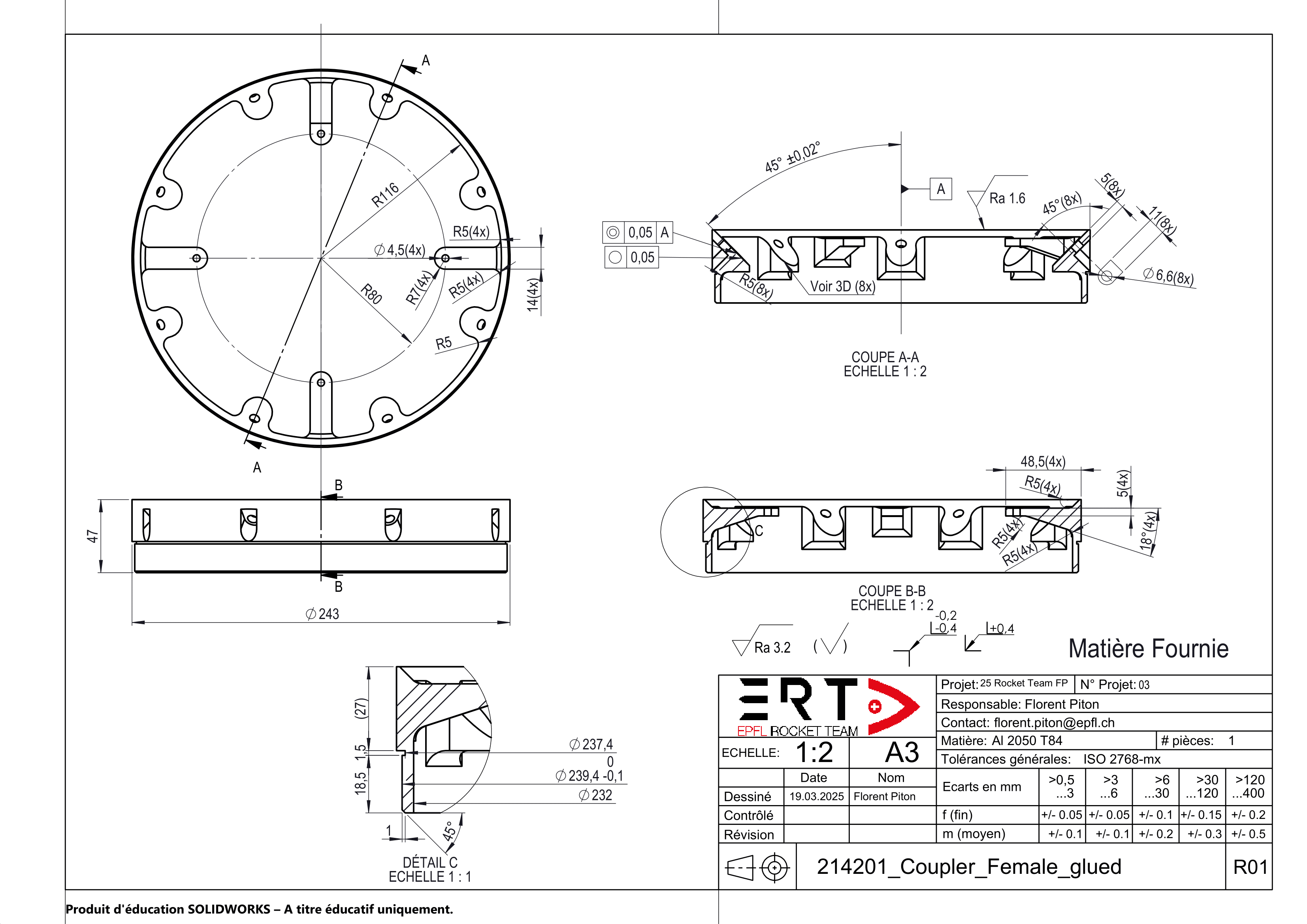
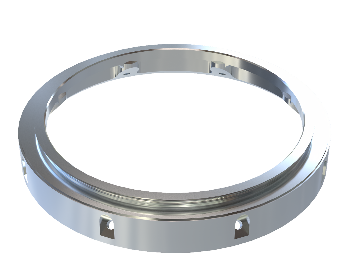
¶ 214201_Coupler_Female_glued
Female iteration designed to be glued to the top part of the recovery bay, whilst supporting a shockplate. In this design we find:
- a flat circumferential area destined to be glued from the outside with epoxy to the recovery bay;
- 4x shockplate support attachments (M4 screws).
¶ Description
| Part Name | Number of Parts | Main Characteristics | Link to .SLDPRT file |
|---|---|---|---|
| 214201_Coupler_Female_glued | x1 | Din=146mm, Dout=243mm, height=47mm, m=558g, glued configuration (b) | 214201_Coupler_Female.SLDPRT |
¶ Technical Drawing
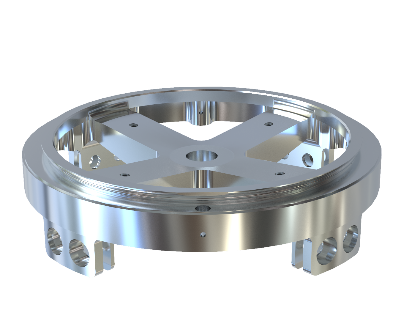
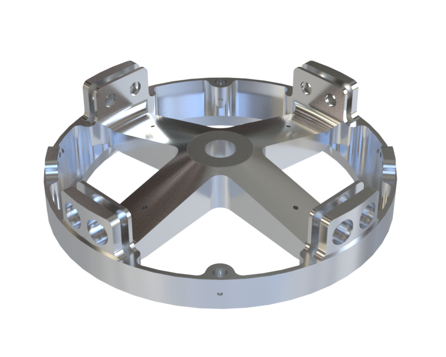
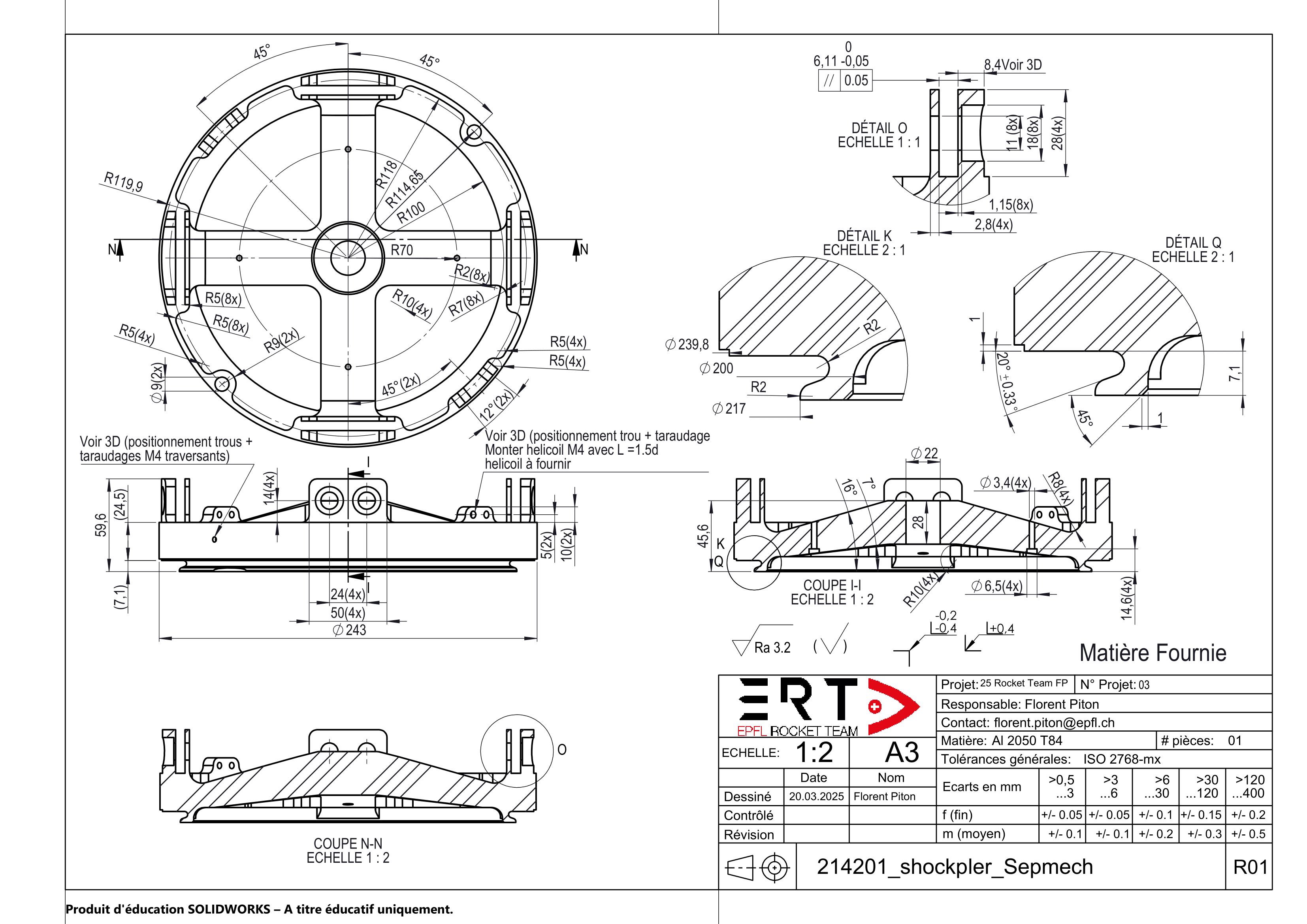
¶ 214201_Coupler_female_shockpler
Female iteration design incoprporating the base female coupler's ear system on one end, as well as a shockplate capable of acting as the linking element between the vehicle and the parachute. The top part of the shockpler includes the Lower ring setup, used in the seperation mechanism. In this design we find:
- 4x standard ears;
- 2x aerocover ears;
- M20 extrusion at the center;
- 4x AIS (avionics system) extrusions, distributed on the branches (M3 screws);
- 2x pyrocutter extrusions (9mm diameter).
- Seperation mechanism 'Lower ring' setup (to be coupled with the 'Upper ring' setup)
¶ Description
| Part Name | Number of Parts | Main Characteristics | Link to .SLDPRT file |
|---|---|---|---|
| 214201_Coupler_Female_shockpler | x1 | Din=22mm, Dout=243mm, height=59.6mm, m=1518g, shockpler configuration (c) | 214201_Coupler_Female.SLDPRT |
¶ Technical Drawing
Vérifier tailles et poids
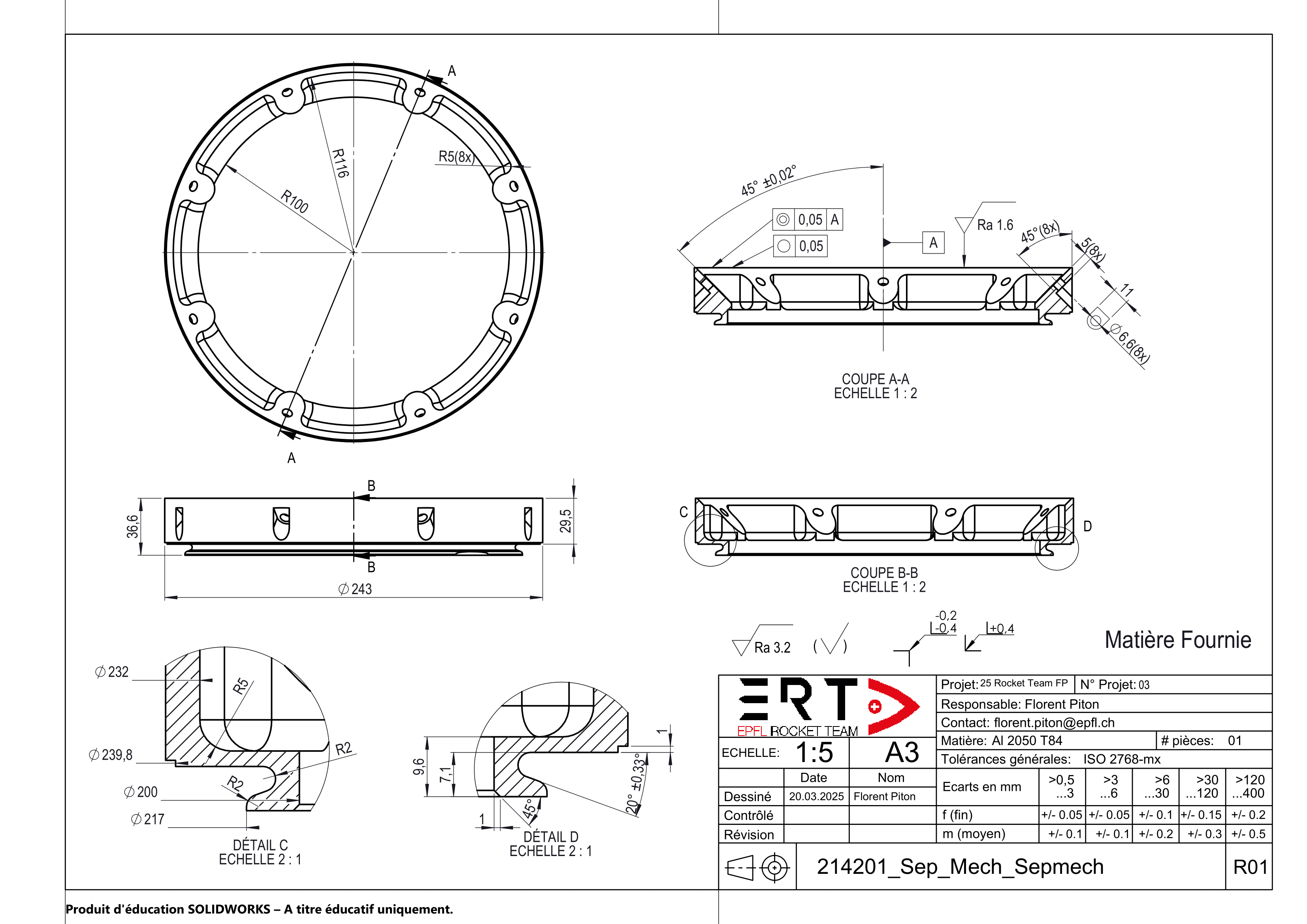
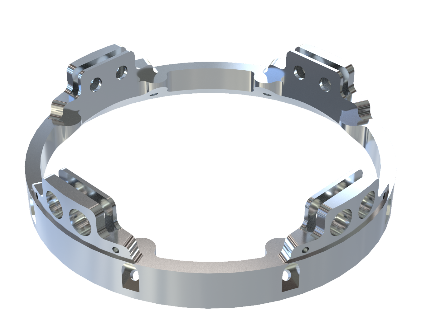
¶ 214201_Coupler_female_sepmech
Female iteration design incorporating, at the its bottom, the top half of the separation mechanism ('Upper ring' setup), allowing it to be fastened to the Shockpler iteration via the seperation mechanism. In this design we find:
- Separation mechanism 'Upper ring' setup (to be coupled with the 'Lower ring' setup).
¶ Description
| Part Name | Number of Parts | Main Characteristics | Link to .SLDPRT file |
|---|---|---|---|
| 214201_Coupler_Female_sepmech | x1 | Din=TBD, Dout=243mm, height=TBD , m=TBD, engine bay configuration (d) | 214201_Coupler_Female.SLDPRT |
¶ Technical Drawing
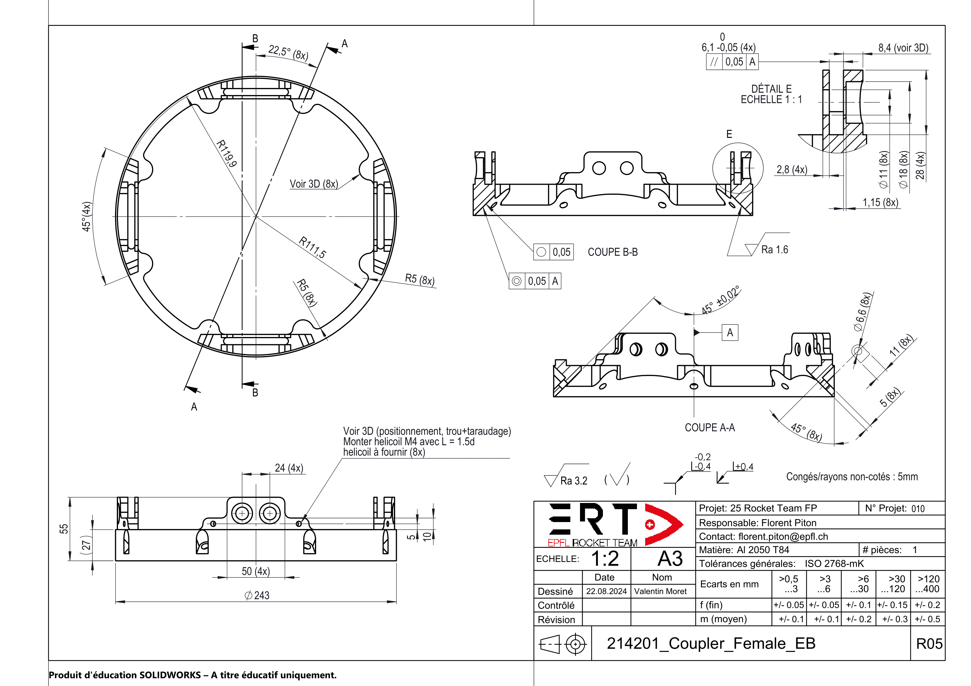
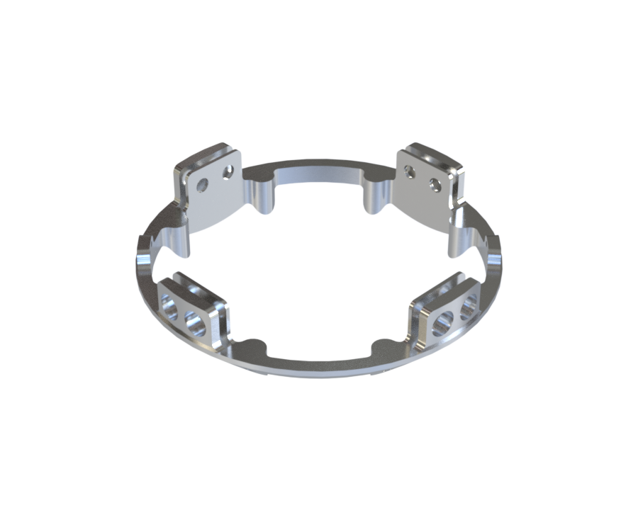
¶ 214201_Coupler_female_engine_bay
Female iteration designed to answer the need of dividing the aerocover pannels in 4 segments instead of 2 (due to the fins). In this design we find:
- 4x standard ears;
- 4x2 cover ears, on each side of the standard ears, to allow for quarter pannels to be used instead of halves, thus simplifying fin attachment (M4 screws).
¶ Description
| Part Name | Number of Parts | Main Characteristics | Link to .SLDPRT file |
|---|---|---|---|
| 214201_Coupler_Female_engine_bay | x1 | Din=195mm, Dout=243mm, height=27mm (ears excluded), m=732g, engine bay configuration (e) | 214201_Coupler_Female.SLDPRT |
¶ Technical Drawing
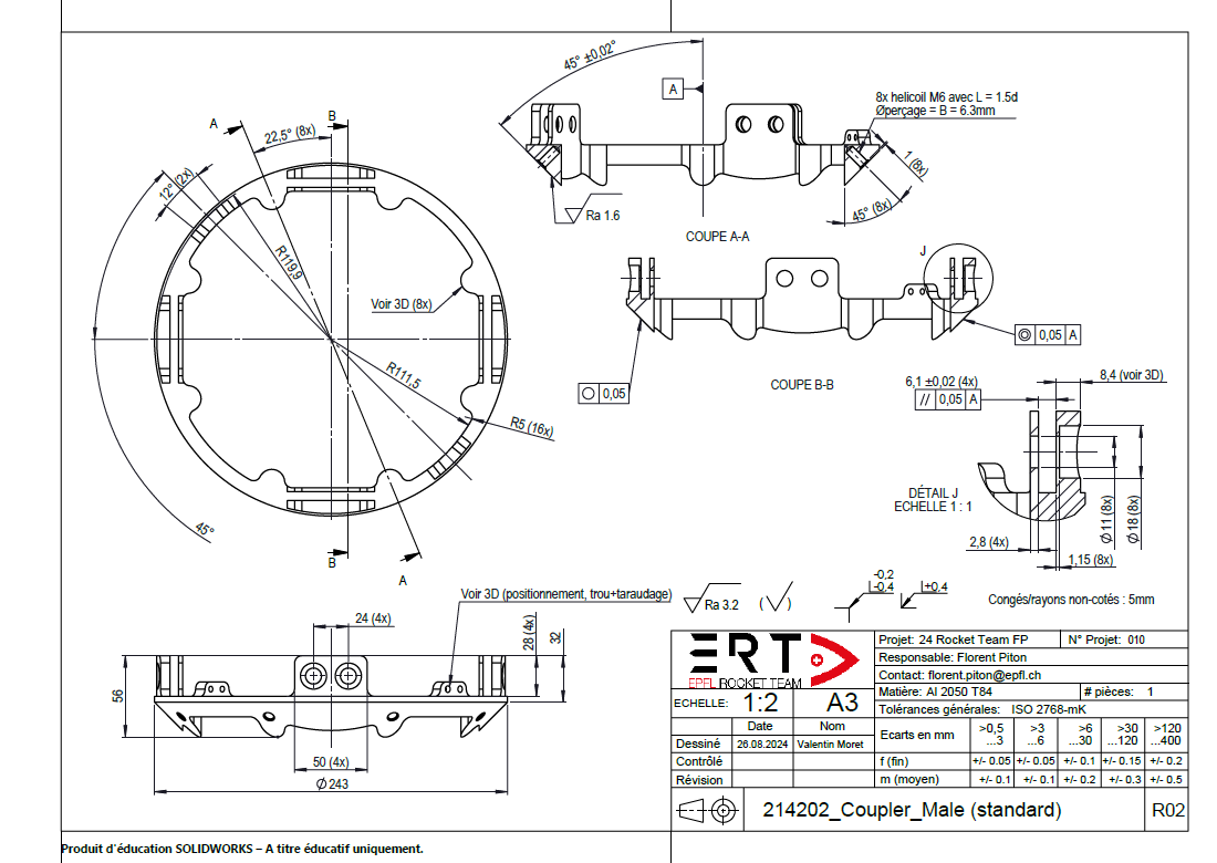
¶ 214202_Coupler_Male
Standard male coupler. In this design we find:
- 4x standard ears (to be screwed using M10 screws to clamp 4 rods);
- 2x aerocover ears (M4 screws);
- 8x 45 degree extrusions that have been discussed above in this document. These will not be mentionned in the iterations below (M6 screws).
¶ Description
| Part Name | Number of Parts | Main Characteristics | Link to .SLDPRT file |
|---|---|---|---|
| 214202_Coupler_Male | x1 | Din=195mm, Dout=243mm, height=28mm (ears excluded), m=495g, standard configuration (f) | 214202_Coupler_Male.SLDPRT |
¶ Technical Drawing
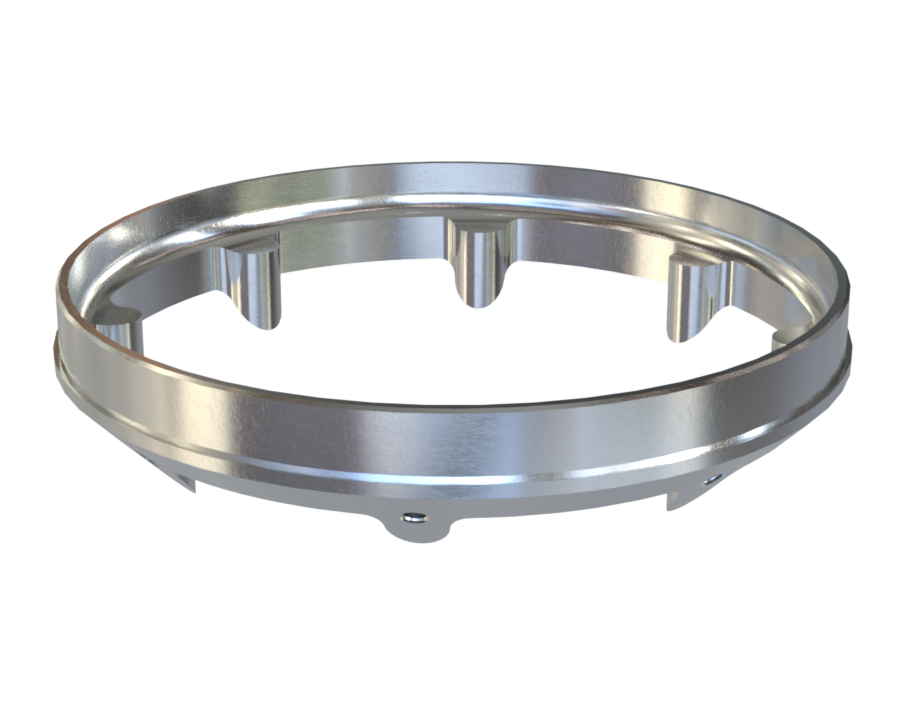
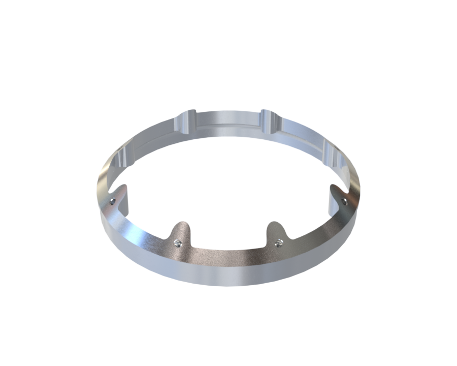
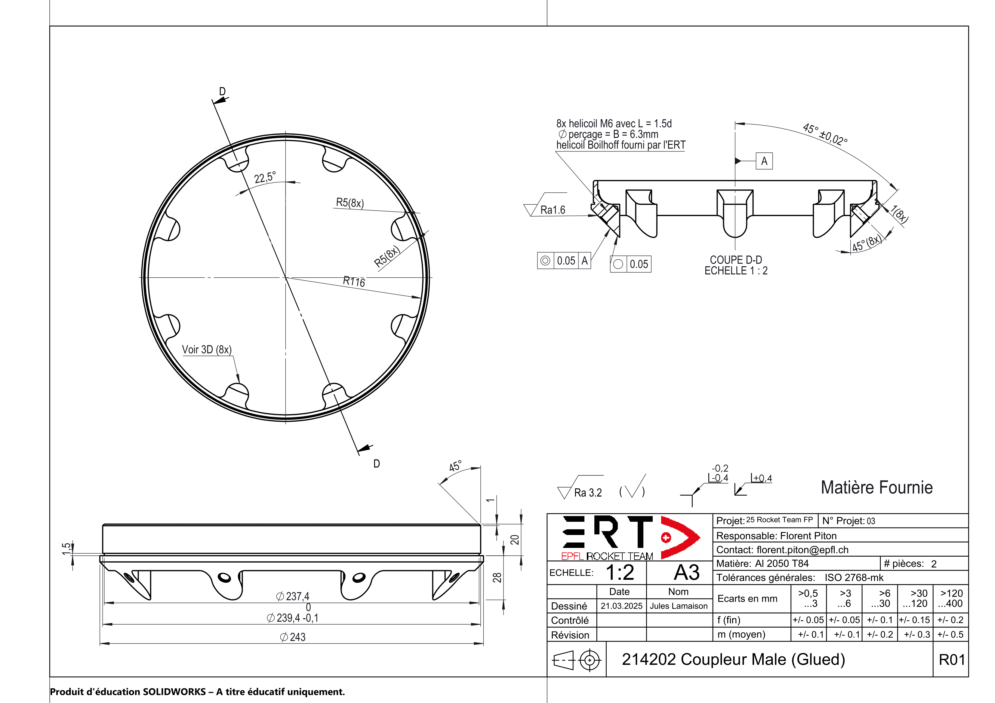
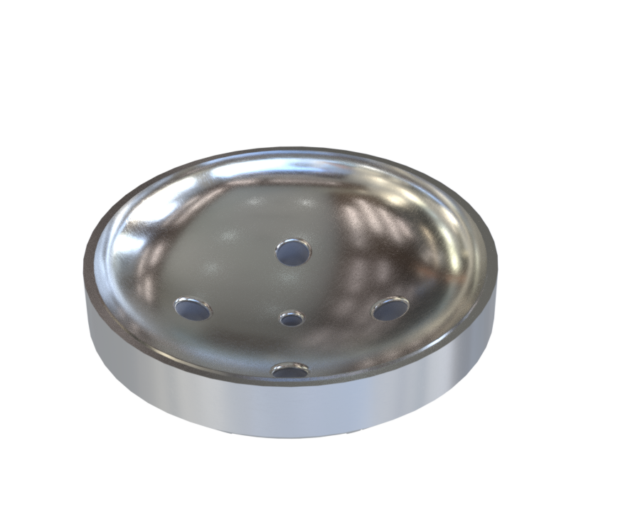
¶ 214202_Coupler_Male_glued
Male iteration designed to be glued to the bottom part of the payload bay (nosecone). In this design we find:
- a flat circumferential area destined to be glued with epoxy to the bottom of the payload bay, as well as to the bottom of the recovery bay.
¶ Description
| Part Name | Number of Parts | Main Characteristics | Link to .SLDPRT file |
|---|---|---|---|
| 214202_Coupler_Male_glued | x1 | Din=195mm, Dout=243mm, height=48mm, m=347g, glued configuration (g) | 214202_Coupler_Male.SLDPRT |
¶ Technical Drawing
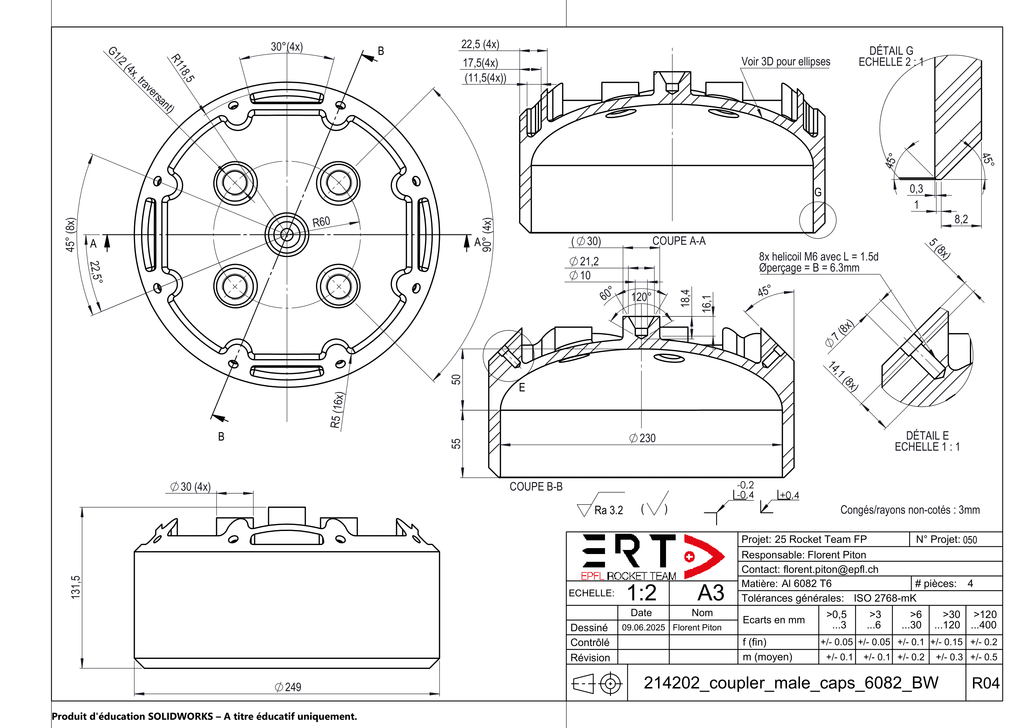
¶ 214202_Coupler_Male_caps
Male iteration designed as caps for all tanks in the vehicle, while allowing different liquids to flow. In this design we find:
- 5x extrusions meant for liquid flow at the center.
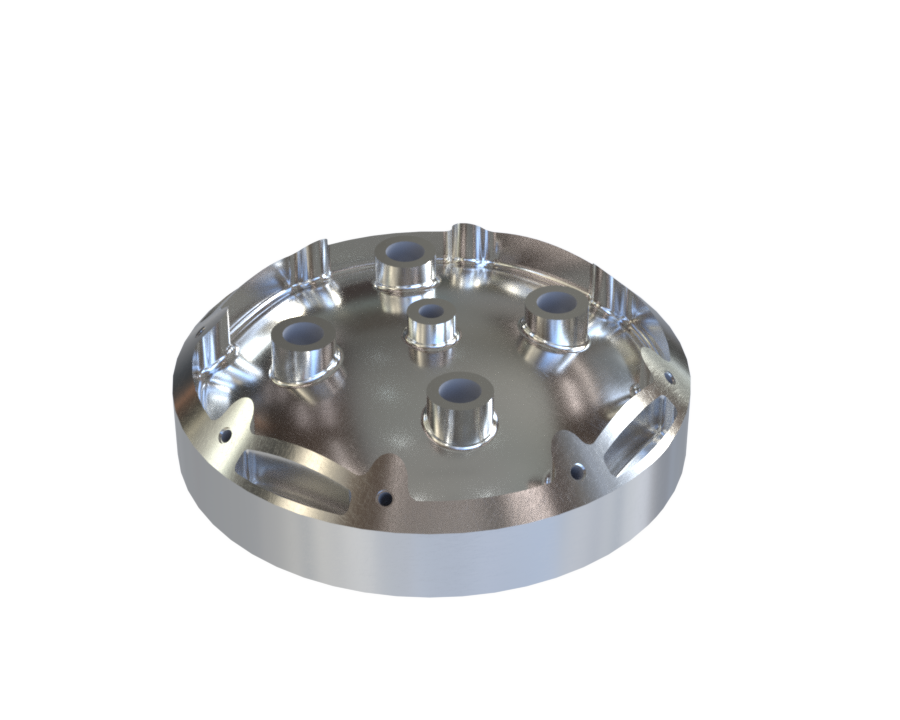
¶ Description
| Part Name | Number of Parts | Main Characteristics | Link to .SLDPRT file |
|---|---|---|---|
| 214202_Coupler_Male_caps | x1 | Din=11.8mm, Dout=243mm, height=62.5mm, m=1669g, tank caps configuration (h) | 214202_Coupler_Male.SLDPRT |
¶ Technical Drawing
¶ Technical Budget, Margins and Deviation
| Type of value | Units | Requirement Value | Actual Value | Deviation |
|---|---|---|---|---|
| Total mass | g | 1200 | 1190 | - 0.8 % |
| Integration diameter | mm | 188 | 195 | + 4 % |
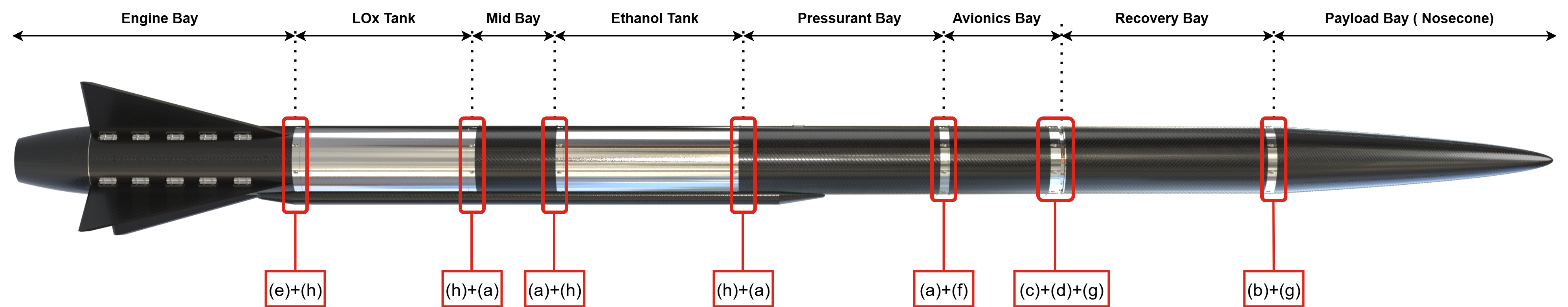
¶ Interfaces
The coupling system has various interfaces driven designs which are summarized below (from top to bottom for each type):
- Female
(a) 4x Standard (presented throughout this document)
(b) 1x Glued (with shockplate screwed on it)
(c) 1x Shockpler (Lower ring, coupler & shockplate are one)
(d) 1x Sepmech (Upper ring)
(e) 1x Engine bay (same as standard but with 4 panel mounts
instead of 2 (one on each quarter)- Male
(f) 1x Standard (presented throughout this document)
(g) 2x Glued
(h) 4x Caps (for tanks)
¶ Design Constraints
¶ Constraints for production
- Criticality of conical surface machining and associated coaxiality defect
- Specific tooling for HELICOIL (tap & installation tool)
¶ Constraints for operations
- Cleaning the conical surface before use (dust should be avoided to guarantee the assembly quality)
- Star tightening with torque wrench in 2-3 passes to ensure a uniform & precise tightening torque
¶ Other constraints
- Protecting conical surfaces when not in use (e.g. transport, storage, etc.) as any damage could be detrimental for the assembly. Thorough protection is achieved by using custom 3D-printed protections as well as bubble wrap at all times when not in use.
¶ Potential improvements, verifications & open points
Throughout the development of this coupling system, a few areas for improvement for future (bigger) rockets were identified and are summarized below.
- Milling of "unuseful" volume within petal arrangement (parallely to angular screws).
- Pockets machining within quarters between two ears (same as planned for anti-buckling rings) if finite element analysis allows it.
- More research on HELICOIL SMART type could be performed as Böllhoff did not recommend them for our application but only for non-operational reasons (costs, minimum order quantity, installation tool price, etc.). This insert type enables a reduced tap depth (see image in Characteristics subsection) to increase internal diameter as well as to reduce assembly height, thus helping to reduce weight.
- For higher diameter rockets or if internal structure with ears is abandoned, it could be possible to increase the number of angular screws while maintaining an uniform pattern (here 8x45°). This would enable the use of lower sized screws, which require lower thread engagement length Li and screw free length Lk to satisfy vibration constraints. Hence, the assembly would be more optimized in terms of "useful" mass, combining the same benefits as stated in the previous point.
- For higher diameter rockets or if M4 angular screws can be used, screw angle should be set to 30° to allow to make better use of the screws in traction, thus improving safety and reducing required preload.
To assess the quality of the coupling system and in particular the quality of contact (conical interface), it is planned to use a special gel (e.g. PERMATEX Prussian Blue) which changes its colour depending on the pressure applied. Combined with measurements of coaxiality defect between modules, it will allow us to verify our machining tolerances choices, and to iterate if necessary.