¶ Introduction
This document presents the design and engineering process behind the design of the Firehorn rocket tanks.
¶ Abbreviations
- LOx : Liquid Oxygen
- ETH : Ethanol
- FoS : Factor of Safety
¶ Applicable and Reference Documents
- 2024_C_ST_PR_LLIM
- 2025_C_ST_TANKS-6082T6_MAP
 2024_C_ST_TANKS_PRESSURE-TSP
- 2024_C_ST_TANKS_PRESSURE_TR
- 2024_C_ST_TANKS_PRESSURE_TR-(BURST)
- 2025_C_ST_TANKS_16L_FEA
¶ Requirements
The tanks assembly must meet the following requirements:
- 2024_C_SE_ST_TANK_REQ_01
Declaration of purpose
The tank shall host the liquid oxygen or the liquid ethanol required for the LV engine.
{.links-list}
This requirement has been verified in these document - 2025_C_ST_TANKS_DDF
- 2024_C_SE_ST_TANK_REQ_03
Tank volume
The tank shall have an internal volume of [25][+/-0.25]L.
{.links-list}
This requirement has been verified in these documents - 2024_C_ST_Tanks_VOLUME_TSP
- 2024_C_ST_Tanks_VOLUME_TR
- 2024_C_SE_ST_TANK_REQ_04
Tank length
The tanks shall have a maximum length of [650]mm each.
{.links-list}
This requirement has been verified in these document - 2025_C_ST_LENGTH_IR
- 2024_C_SE_ST_TANK_REQ_05
Tank coupler integration
Couplers of the 'male' type shall be integrated on the both ends of the tank.
{.links-list}
This requirement has been verified in these document - 2025_C_ST_TANKS_DDF
- 2024_C_SE_ST_TANK_REQ_07
Tank mass
The total mass of the tank module shall be maximum [10100]g.
{.links-list}
This requirement has been verified in these document - 2025_C_ST_MASS_IR
- 2024_C_SE_ST_TANK_REQ_09
Tank yield pressure
The tank shall not yield under an internal pressure of [90]bars for [30] minutes.
{.links-list}
This requirement has been verified in these documents - 2024_C_ST_TANKS_PRESSURE-TSP
- 2024_C_ST_TANKS_PRESSURE_TR
- 2024_C_SE_ST_TANK_REQ_26
Tank burst pressure
The tank shall not burst under an internal pressure of [120]bars.
{.links-list}
This requirement has been verified in these document - 2024_C_ST_TANKS_FEA
- 2024_C_SE_ST_TANK_REQ_12
Tanks interchangeability
The tank containing the liquid oxygen shall be mechanically identical to the tank containing the liquid ethanol so that both tanks may be interchangeable.
{.links-list}
This requirement has been verified in these document - 2025_C_ST_TANKS_DDF
- 2024_C_SE_ST_TANK_REQ_25
Design Scaleability
The tank design shall be upgradeable to contain [60]L for the [30]km flight by only changing the length and thickness of the tank.
{.links-list}
This requirement has been verified in these document - 2025_C_ST_TANKS-6082T6_MAP
¶ Interfaces
- 2024_C_ST_PR_LLIM Structure / Propulsion Low Level Interface Management
¶ Overview
The tanks are the parts of the rocket that contain the rocket engine's fuel and oxidizer. This year the rocket is equiped with a bi-liquid engine, and therefore two tank modules are required. One tank is filled with LOx at -183[°C], while the other is filled with Ethanol. The two propellants are pressurised at 60[bar] using nitrogen gas. Furthermore, the tanks are structrual parts of the rocket which mean they shall withstand all the flight loads and constraints. To facilitate manufacturing, both tanks are identical in terms of capacity and design. Both ends of each one are also identical so that only one type of cap is produced. The caps and tubes are made of Al-6082T6 and are welded together.
¶ Main Specifications
| Specification | Value | Unit |
|---|---|---|
| Dimensions | 243 x 243 x 454.6 | [mm] |
| Capacity | 16 | [L] |
| Mass | 7979 | [g] |
| Material | Al-6082T6 | |
| Design Load | 120 | [bar] |
| Nominal pressure | 60 | [bar] |
| Test pressure | 60 | [bar] |
| Factor of Safety | 2 | |
| Manufacturing | 5-axis CNC |
¶ Interfaces
The LOX tank is connected to the engine bay and the mid bay by a female coupler. The ethanol tank is connected to the mid bay and the pressurant bay by a female coupler.
For more informations :
All other interfaces with the plumbing are listed in the following document :
¶ Analysis and Simulations
¶ Parts Description
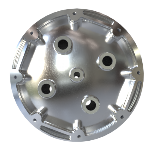
¶ Coupler-CAP
The coupler-caps are welded to both ends of the cylindrical tube. They are all identical and feature a male coupler interface, 4 G1/2 holes, and 1 G1/4 hole. They are machined using a 5-axis CNC machine from a cylindrical Al-6082T6 beam. The caps are first pre-machined with a diameter of 249 mm, an ellipsoidal cavity inside and excess material on the conical interface. This excess allows the two ends to be realigned after deformation due to welding. Instead of having a G1/4 hole in the center, they are equipped with an interface for a centering tip to facilitate machining of the outer diameter after welding. The interface of the centering tip is then machined to become a G1/4 hole.
Since welds are the weak points of the tanks, they are located away from the highest stresses at the beginning of the ellipsoid. The caps therefore have a cylindrical length of 55 mm.
| |
|
| Cap top view before welding |
|---|
¶ Main Specifications
| Specification | Value | Unit |
|---|---|---|
| Dimensions | 249 x 249 x 131.5 | [mm] |
| Mass | 3316 | [g] |
| Material | Al-6082T6 | |
| Design Load | 120 | [bar] |
| Factor of Safety | 2 | |
| Manufacturing | 5-axis CNC | |
| Cost | 2180 for 4 caps | [CHF] |
Be aware that the larger the bulk, the lower the yield strength. The theoretical yield strength of Al-6082T6 is 270 MPa. According to the supplier, the raw material (full cylinder) with a diameter of 250mm has an elastic limit of 200MPa. So it's important to look at the supplier's properties, not the Internet's theoretical ones.
After welding the caps onto the cylindrical tube, all tanks are machined to obtain the appropriate outer diameter and conical interface.
 |
 |
|---|---|
| Cap side view after final machining | Cap top view after final machining |
¶ Possible Improvements
The excess material on the conical surface was 5 mm. This is too thick and takes too long to remove. This needs to be discussed with the workshop, but 1 or 2 mm seems sufficient to realign the two ends.
Following a pressure test that caused the tank to explode, the cylindrical length of the cap was increased from 2 mm to 55 mm. The reason for this was to move the weld away from the maximum stresses. This results in expensive and bulky caps. An improvement could be to reevaluate the cylindrical length and find the right balance between cost and internal stresses.
To reduce mass, material can be removed from under the carbon rods.
We had decided to keep an outer diameter of 249 mm before welding in order to avoid machining the tube (raw diameter: 250 mm) prior to welding, which would have increased cost and machining time.
The problem with this choice is that post-weld machining involves, by extension, machining the welds, which increases the risk of porosity and leakage.
A possible improvement would be to use a smaller outer diameter before welding—for example, 246–247 mm which would require removing only 2 mm of weld thickness.
With an outer diameter of 246–247 mm, it might even be possible to avoid machining the welds altogether and only machine the remaining material, thereby increasing the chances of preventing leaks.
¶ Tube
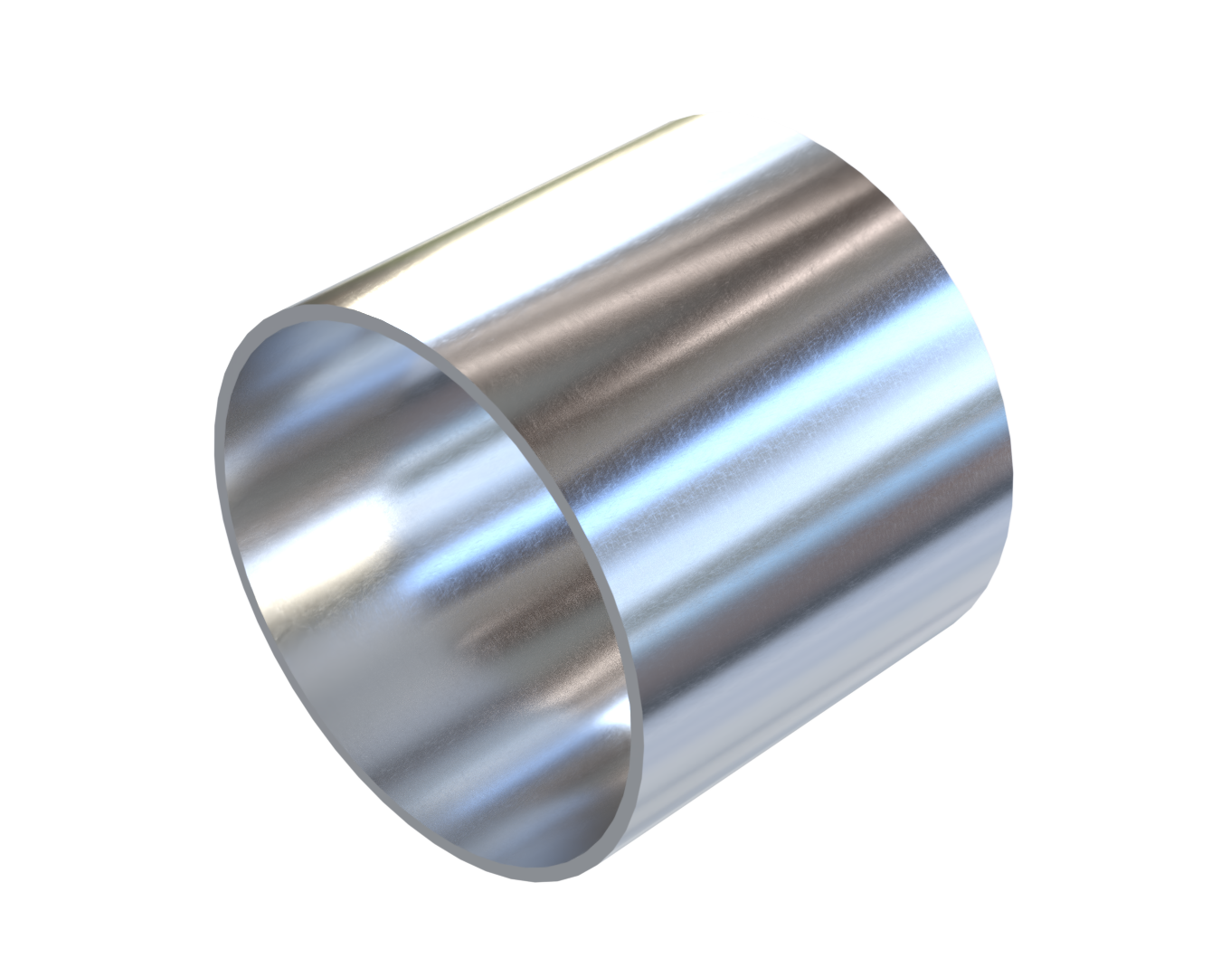
¶ Main Specifications
| Specification | Value | Unit |
|---|---|---|
| Dimensions | 243x243x209 | [mm] |
| Dia. int | 230 | [mm] |
| Manufacturing | Lathe | |
| Cost | 985.- for 3 tube of 580mm length | [CHF] |
| Material | Al-6082T6 |
¶ Technical Budget, Margins and Deviation
| Type of value | Units | Requirement Value | Actual Value | Deviation |
|---|---|---|---|---|
| Dimensions | mm | 243x243x650 | 243 x 243 x 454.6 | - 31 % |
| Weight | kg | 10100 | 7979 | - 21 % |
¶ Design Constraints
Since no annealing was performed after welding, we assumed during the design phase that the material properties were reduced by 50% due to the welds.
¶ Constraints for Production
All production constraints are listed in the document bellow :