¶ Introduction
¶ Purpose, Objective and Scope
The purpose of this document is to list the stages in the manufacture of Al-6082T6 tanks. It also includes lessons learned during the manufacturing process, as well as all the iterations that led to the final product.
¶ Applicable and Reference Documents
The following documents detail other aspects of this assembly and may provide important elements for understanding this DDF.
- 2024_C_ST_PR_LLIM
- 2025_C_ST_TANKS_DDF
 2024_C_ST_TANKS_PRESSURE-TSP
- 2024_C_ST_TANKS_PRESSURE_TR
- 2024_C_ST_TANKS_PRESSURE_TR-(BURST)
- 2025_C_ST_TANKS_16L_FEA
- Definitive Production Batch ATME
- Definitive Production Batch PLTE
- Scanning welds on exploded tanks
- Scanning welds on final tanks
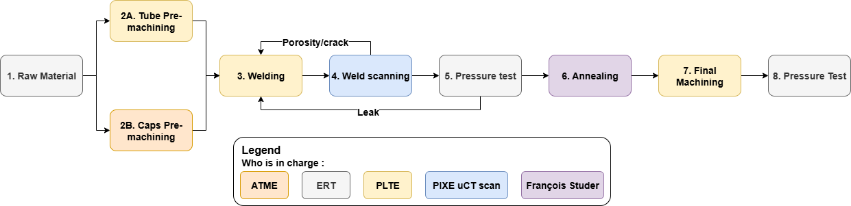
¶ Production Overview
¶ Parts List
| Description | Part Ref | Qty |
|---|---|---|
| Caps | 214202_Coupler_Male_caps_6082_BW_V2 | 4 |
| Tubes | 215101_Tank_main_section_6082_BW | 2 |
¶ 1. Raw Materials
For the 4 caps, a 250 mm OD cylindrical beam in Al-6082T6 was used as the raw material.
Supplier : ThyssenKrupp
Be aware that the larger the bulk, the lower the yield strength. The theoretical yield strength of Al-6082T6 is 270 MPa. According to the supplier, the raw material (full cylinder) with a diameter of 250mm has an yield strength of 200MPa. So it's important to look at the supplier's properties, not the Internet's theoretical ones.
| Dimesion | Diameter | Hight | Quantity |
|---|---|---|---|
| Caps | 249 [mm] | 131.5 [mm] | 4 |
| Bulk | 250 [mm] | 138 [mm] | 4 |
For the tube, a 250 mm OD tube in Al-6082T6 was used as the raw material.
Supplier : WMH GROUP GERMANY
| Dimesion | Diameter | Hight | Quantity |
|---|---|---|---|
| Tube | 250 [mm] | 209 [mm] | 2 |
| Bulk | 250 [mm] | 580 [mm] | 1 |
¶ 2A. Tube Pre-machining
This stage consists of cutting the raw material to the desired length and machining the weld interfaces. The raw material was cut into 2 parts. The two segments were cut to a length of 209 mm. The excess material (162 mm) was used for test welding to adjust the welding parameters.
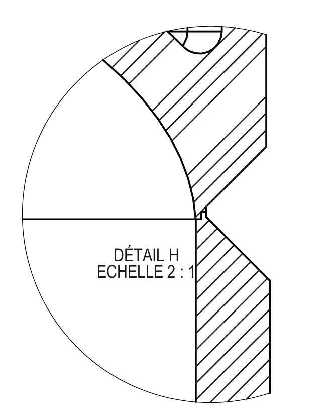
On caps and tubes, the weld interfaces consist of two chamfers, as shown in the image below :
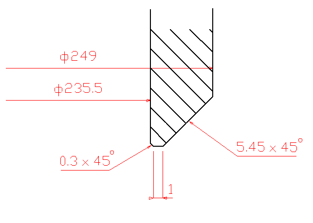
It is very important to discuss the interface with the workshop before finalizing the design. It depends on several parameters such as material used or thickness and must be adapted to the workshop's capacity.
| Machining time | x [h] |
| Price | x [CHF] |
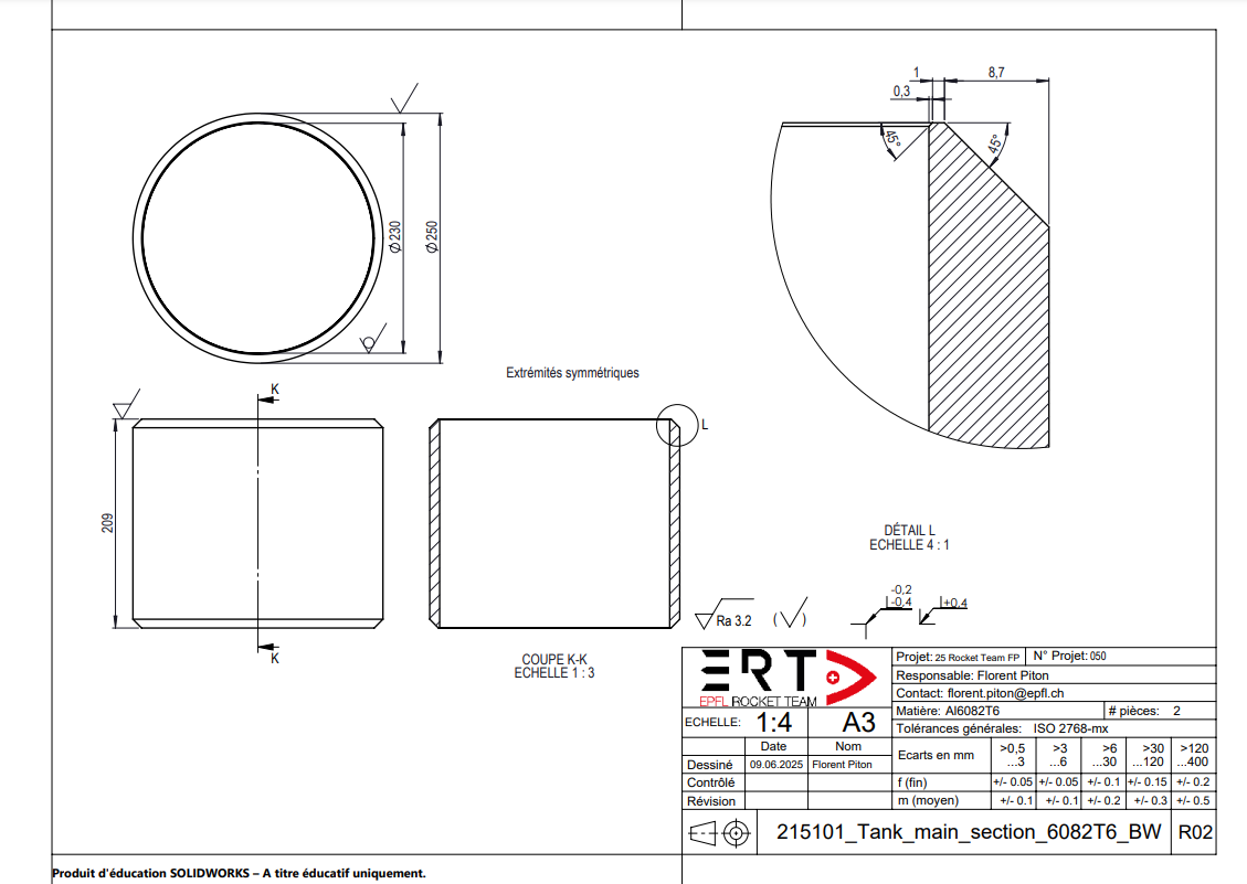
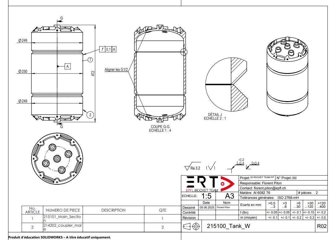
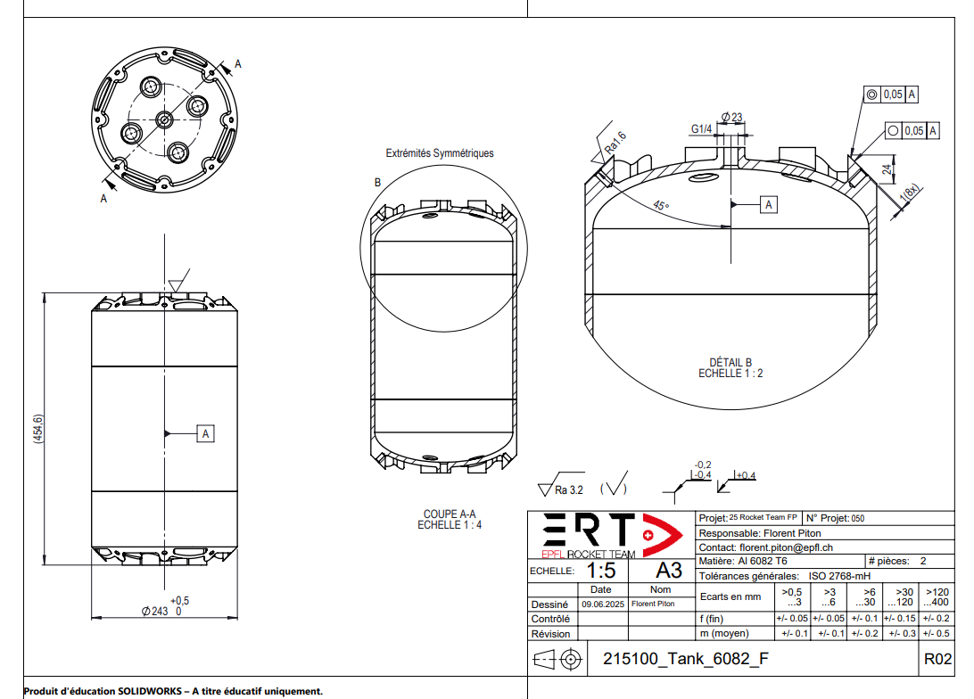
¶ Technical drawings
¶ Possible Improvements
We had decided to keep an outer diameter of 249 mm before welding in order to avoid machining the tube (raw diameter: 250 mm) prior to welding, which would have increased cost and machining time.
The problem with this choice is that post-weld machining involves, by extension, machining the welds, which increases the risk of porosity and leakage.
A possible improvement would be to use a smaller outer diameter before welding—for example, 246–247 mm which would require removing only 2 mm of weld thickness.
With an outer diameter of 246–247 mm, it might even be possible to avoid machining the welds altogether and only machine the remaining material, thereby increasing the chances of preventing leaks.
¶ 2B. Caps Pre-machining
This step can be carried out at the same time as tube pre-machining. It involves pre-machining the caps and preparing them for welding. The welding interface is identical to that of the tubes. As welding can involve deformation, the conical surface has an excess of material which must be machined after welding to realign the two ends. This excess of material is 4 mm. In the center, instead of having a G1/4 hole, the caps have a centering point which is used to machine the outside diameter of the tank after welding. In the end, this centering point is removed and transformed into a G1/4 hole.
It is very important to discuss with all the workshops involved in the machining of the tanks before finishing the design. The aim of these discussions is to take into account potential modifications in the design to facilitate machining. Without the centering point, machining the outside diameter would have been much more costly and time-consuming.
| Machining time | 70 [h] |
| Time in workshop | 2-3 weeks |
| Price | 1400 [CHF] |
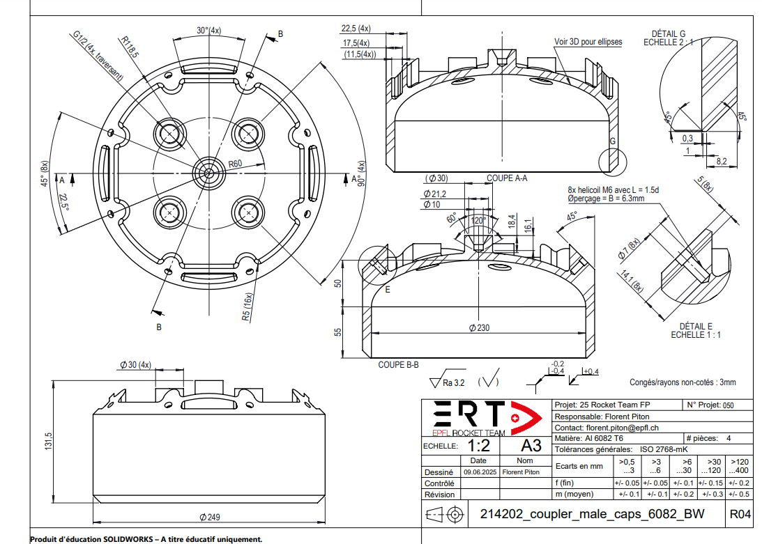
¶ Technical drawings
¶ Possible Improvements
Following a pressure test that caused the tank to explode, the cylindrical length of the cap was increased from 2 mm to 55 mm. The reason for this was to move the weld away from the maximum stresses. This results in expensive and bulky caps. An improvement could be to reevaluate the cylindrical length and find the right balance between cost and internal stresses.
In order to save time and money during final machining, the G1/4 threading can already be done when pre-machining the caps. Be careful to keep the interface of the counterpoint.
In order to facilitate tightening the fittings, it is strongly recommended to make two flat surfaces on the outer diameter of the tank fittings. This allows a wrench to be placed and counteracts the tightening torque.
¶ 3. Welding
As the test pressure is 90 bar, it is essential to have a homogeneous weld without porosity, cracks or cavities. The use of a tacker is strongly recommended, to ensure consistency during welding and reduce seam welding.
| Machining time | 9 [h] |
| Time in Workshop | 1 week |
| Price | 500 [CHF] |
¶ Technical drawings
¶ 4. Weld Scanning
Welds must be scanned for porosities, cracks or cavities detection.
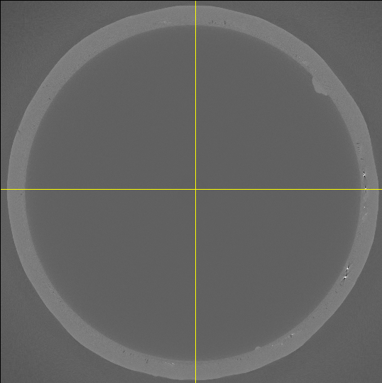
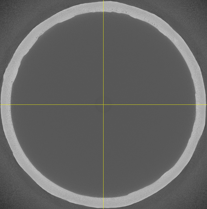
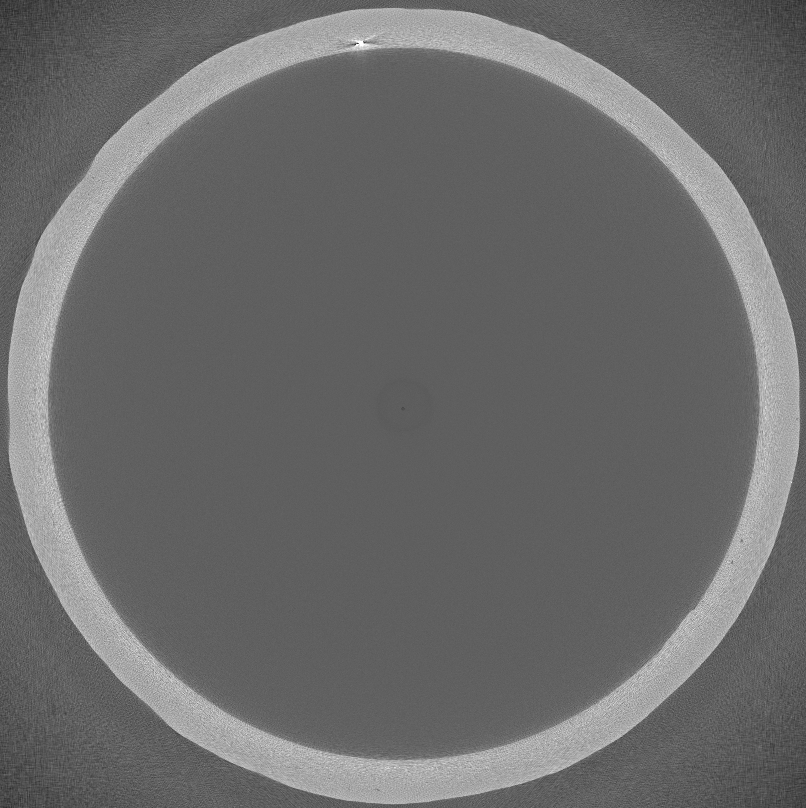
Scans of the welds on both tanks are listed below:
.png) |
 |
|---|---|
| Res1 V2 a | Res1 V2 b |
In tank 1, some porosity can be observed, particularly in weld a, represented by black spots inside the weld. However, it is still considered to be of good quality. Weld b, on the other hand, shows white spots representing either inclusions or melting irregularities. Despite these defects, the weld is generally homogeneous.
 |
 |
|---|---|
| Res2 V2 a | Res2 V2 b |
In tank 2, both welds are homogeneous and show little porosity. A white spot is visible in weld B, representing an inclusion or irregular fusion. Both welds are considered to be of good quality.
In the case of a worrying inclusion, crack or cavity, it is possible to re-weld locally. However, it's important to bear in mind that this involves local stresses, leading to deformation and possible cracking during the pressure test. It is therefore important to consider the risks of re-welding.
| Time | 2 [h] |
| Time in Workshop | 2 days |
| Price/tank | 150 [CHF] |
¶ 5. Pressure Test
The purpose of this intermediate pressure test is to validate the welds before machining the outside diameter. In the event of a leak or rupture, it saves the cost of final machining.
This test involves pressurizing the tank to 90 bar for 20 minutes. If the pressure loss is equal to or less than 0.1 bar per minute, the test is considered successful.
| Time | 1 half day |
¶ 6. Annealing
The aim of annealing after welding is to restore the material properties that were reduced during welding. It involves reannealing the entire tank to T6.
This step was not carried out for the current tanks, as we were lagging behind in production. Moreover, we haven't figured out how to quantify the gain from this annealing and whether it is really necessary.
The first tank produced underwent T6 annealing. The tank that did not explode and withstood 84 bar does not appear to have been deformed by the pressure, unlike the final tanks, which were not annealed. It is therefore highly recommended that further research be carried out into this annealing process to determine its real added value. If annealing restores the material's properties, it could reduce the wall thickness of tubes and caps, as the material is more resistant.
| Time | 2 weeks |
| Price | 400 [CHF] |
¶ 7. Final Machining
Final machining consists of 3 steps:
- External diameter machining: Diameter reduction from 249mm to 243mm
- Machining of conical surfaces: reduction of thickness and alignment of both ends.
- Machining the counter-tip interface: Transform the counterpoint of each cap into a G1/4 hole.
| Machining time | 40 [h] |
| Time in Workshop | 3-4 weeks |
| Price | 2500 [CHF] |
¶ Technical drawings
If too much porosity is visible during machining, it was discussed with the workshop that an extra thickness could be left at the welds. The entire tank would therefore be machined to an external diameter of 243, except for the welds, which would be machined to 245-247mm.
Wherever possible, it is preferable not to machine the welds.
¶ Possible Improvements
¶ 8. Pressure Test
This test involves pressurizing the tank to 90 bar for 20 minutes. If the pressure loss is equal to or less than 0.1 bar per minute, the test is considered successful.
If a leak appears during the test, depressurize and mark the leak. It is possible to repair the leak by spot welding. However, be careful not to weld only on the surface. In order to repair the leak as effectively as possible, weld at least 20 to 50 mm wide and deep to the root of the original weld.
If you succeed in this step without having had any problems in the last few steps, it's a miracle. good luck, young padawan.
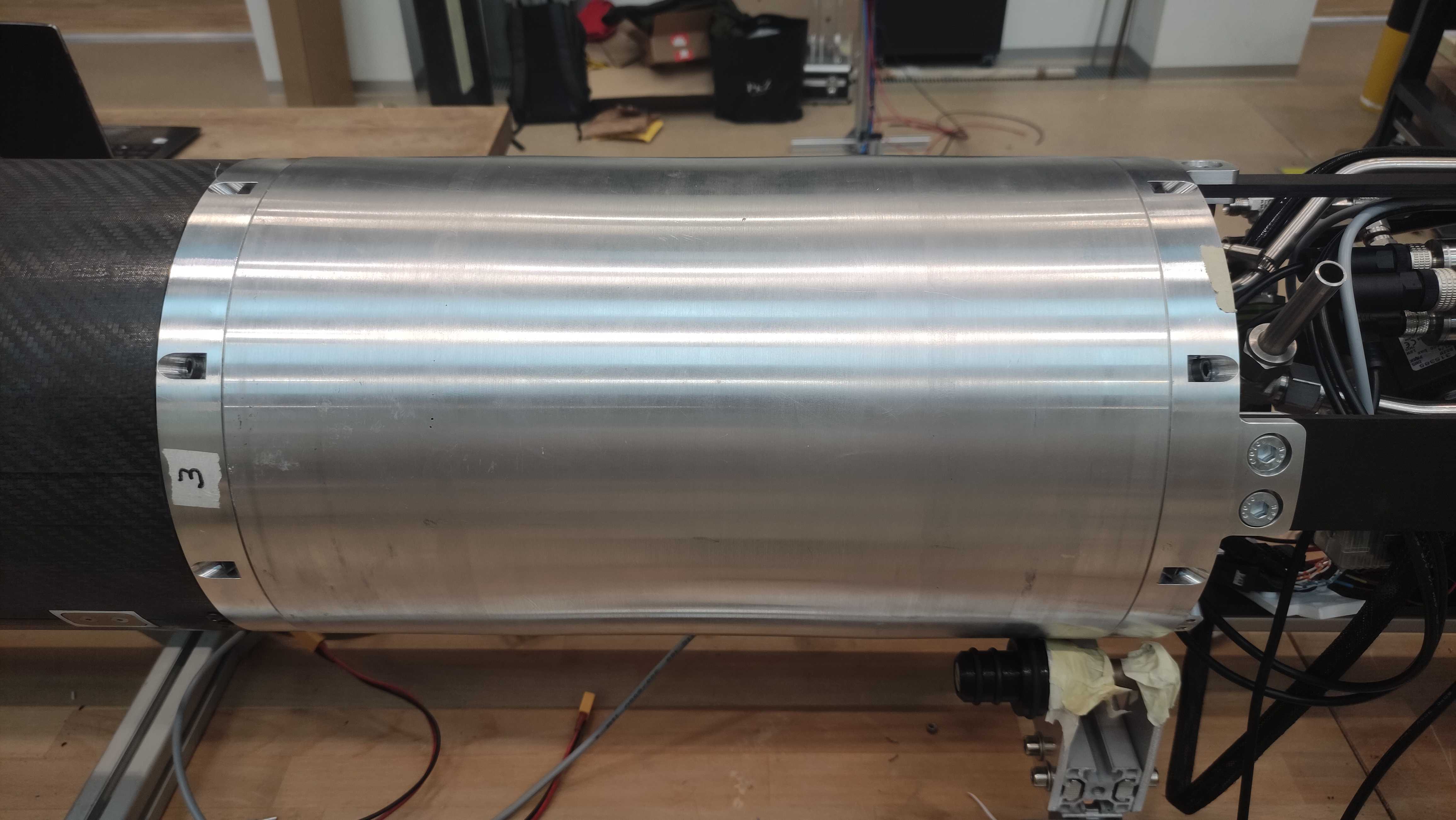
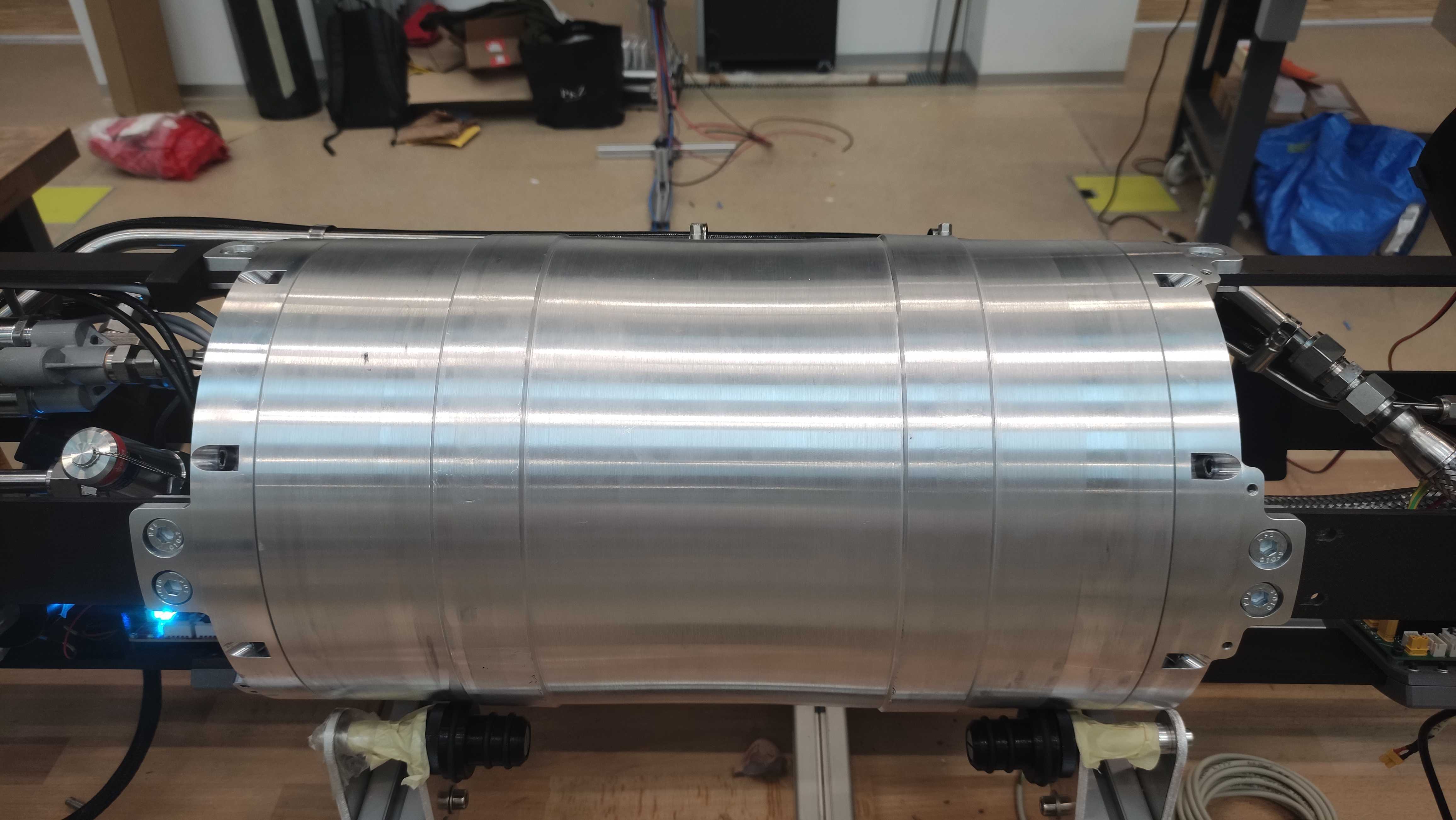
¶ Results
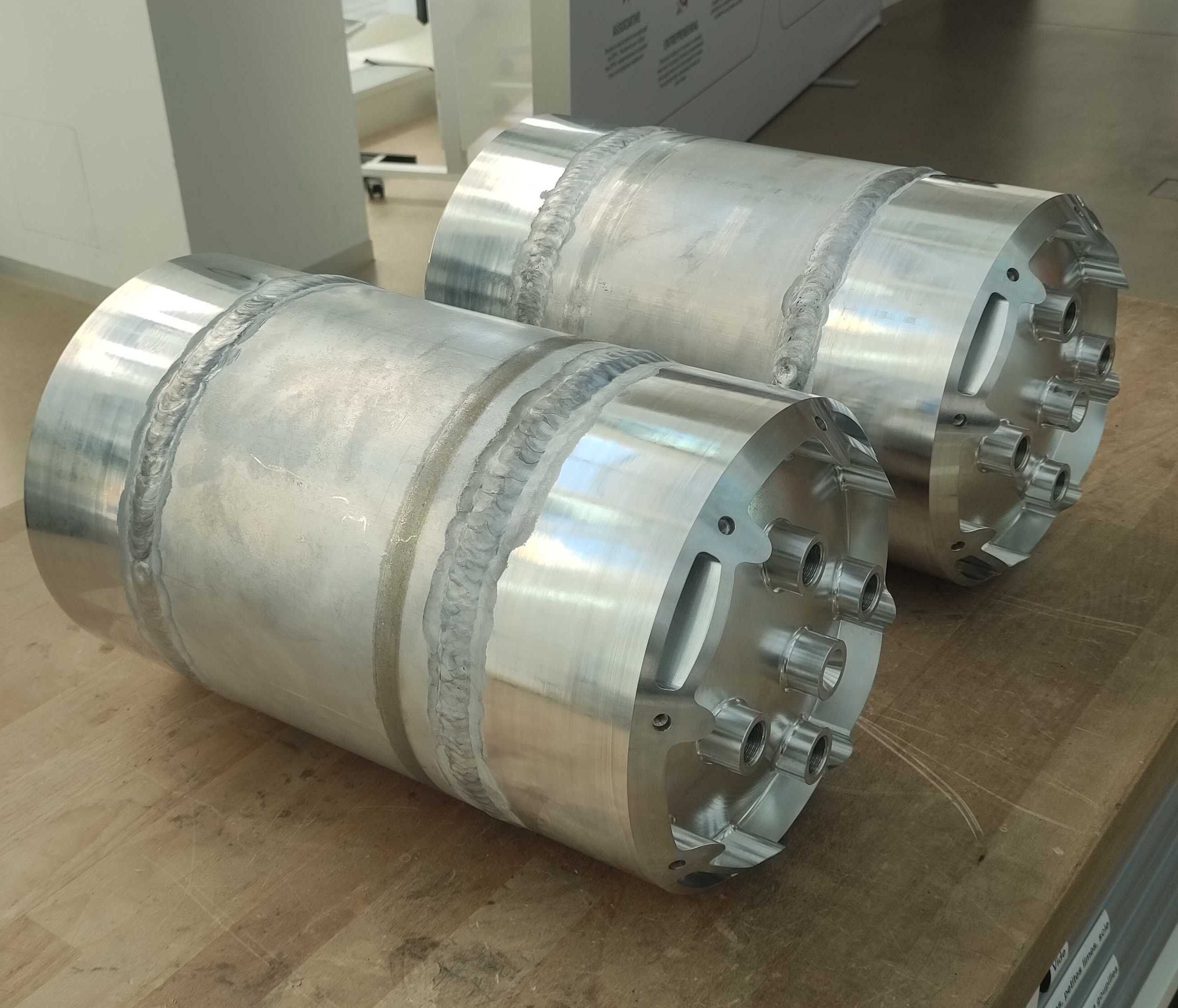
As a final result, we obtain two different tanks. The first has a discontinuous outer diameter increasing from 243 mm to 247 mm at the welds. It therefore has two 40 mm wide bands at the two welds. The welds on the first tank were considered to be of lower quality than the first, and this excess material was intended to increase safety in the event of a potential leak. Despite this excess material at the welds, a leak was still detected. The leak was repaired by re-welding the area. As a precaution, the excess material from the re-weld was left rough and was not machined.
¶ Lesson Learned
This chapter lists the errors made during the manufacture of tanks and explains how to avoid them.The first iterations of the Al-6082T6 tanks had a capacity of 25L and underwent a destructive test.
For a detailed report on the manufacturing of the first iteration, click on this link:
Here is a list of the differences between the first iteration and the final version
¶ Welding Zone
- In order to minimize the machining costs of the caps, their cylindrical part was reduced to a minimum. This resulted in the weld between the cap and the tube being positioned in the area where the stresses are highest.
Having too large a cylindrical span significantly increases machining costs. It is therefore necessary to find the right balance between the position of the welds in respect to the stress and the cost of production.
¶ Wall Thickness
- The wall thickness was reduced in order to reduce mass, but this resulted in a decrease in the strength margin.
Keep in mind that the properties of the material are reduced by 50% locally due to welding. Furthermore, with the equipment we currently have available, it is difficult to guarantee a perfect aluminum weld (without porosity or defects). This is why it is necessary to maintain a comfortable margin on the wall thickness.
¶ Welding Interface
The welding interface was inspired by the one made on Nordend. It consisted in fitting the cap into the tube as illustrated below:
This type of interface has the advantage of offering very good centering without difficulty, but poses two problems:
- The fitting prevents the weld from penetrating and fusing the two pieces at the root.
- The lip of the cap can lift and deform due to pressure, causing a crack to form.
Do not reproduce this interface. Although it helps to align the caps, it is not suitable for pressures higher than 60 bar.
Before defining the welding interface, you need to talk to the workshop that will be doing the work.
¶ Welding Quality
The welds on the first iteration of the tanks were made without a turret. They were irregular, full of porosity and artifacts, and lacked filler material.
It is therefore essential to use a turret in order to achieve a consistent and uniform weld.
After scanning, some cavities were filled by reworking the welds. We believe that excessive and repeated reworking causes local deformation and therefore stress concentration. It is therefore probably safer to minimize reworking of welds.