¶ Introduction
¶ Purpose, Objective and Scope
This document is separated in to two sections, the test specification and the test procedure.
The test specification section defines the purpose of the test, the test approach, the item under test, test sequence, test facility, pass/fail criteria, required documentation, participants and test schedule.
The test report section gives directions for conducting a test activity in terms of description, resources, constraints and provides detailed step‐by‐step instructions for conducting test activities with the selected test facility and set‐up.
This document covers the preparation and procedure for carrying out torque application tests on screws to ensure they withstand applied loads, verifying that the applied torque is sufficient to resist these loads without failure.
In particular, it focuses on the screws of the internal structure. The torque applied in these screws will be studied as a function of the tensile load given in the requirements corresponding to parachute deployment.
It provides the guidelines to the person performing such tests.
It covers the testing protocol as well as the different points of analysis.
It does not cover the actual analysis of the results, neither the test report.
¶ Test Documentation
There are 3 main types of types of documents which relate to testing activities.
¶ AI&T
- High level overiew of testing activities
- Highlights dependancies in between types of tests
- Tracks the status of each type of test
- Document should be prepared as early as possible after PDR
¶ TSP
-
Test specification section explains:
- What part/assembly is being tested during each test.
- What characteristic is being tested.
- Brief description as to how the test is goind to be conducted.
- Explains the Pass/Fail criteria for each step.
- Explains when the test is due to happen and who will be involved in the test.
-
Document should be prepared after the baseline AI&T and ~1 month before the actual test.
-
Test procedure serves as a detailed plan for each individual test, it contains (among other things):
- A list of tools and instrument needed for the test.
- A description of the test location and condition.
- A step by step procedure of what needs to be done before, during and after the test.
-
Document should be prepared after the test specification and at least ~1 week before the actual test.
¶ TR
- The test report contains:
- The "as run procedure", meaning the procedure as planned ~1 week before the test with all of the comments and modiciations which were done the day of the test.
- The results of the test and all of the test data (or at least a link to the test data).
- If applicable, the analysis of the test data.
- The conclusion.
- The baseline document should be prepared the day of the test and the final version should be ready ~1 week after the test
¶ Definitions and Abbreviations
- ST : Structure
- FoS : Factor of Security
- ERT : EPFL Rocket Team
- CFRP : Carbon Fiber Reinforced Polymer
- GRP : Glass Reinforced Plastic
- FEA : Finite Elements Analysis
¶ Applicable and Reference Documents
- 2024_C_ST_INTERNAL-STRUCTURE_DDF
- 2024_C_ST_ROD_FEA_2
- 2024_C_ST_CFRP-PLATE_MAP
- 2024_C_ST_TRACTION_ROD_TSP
- 2024_C_ST_INTERNAL-STRUCTURE-SCREWS_TR
¶ Requirements to be verified
The internal structure assembly must meet the following requirements:
- 2024_C_SE_ST_INTERNAL-STRUCTURE_REQ_01
Declaration of purpose
The internal structure shall withstand all main loads experienced by the LV.
- 2024_C_SE_ST_INTERNAL-STRUCTURE_REQ_04
Axial traction
The internal structure shall withstand [132000]N of axial tensile loads.
¶ Test Specification
¶ Open issue, Assumption and Constraint
Constraints: The machine speed is not as fast as the parachute deployment, which does not allow applying force exactly as in flight conditions.
¶ Test Objectives
This test is carried out to check that the torque applied to the internal structure screws is well defined and guarantees structural integrity during the tensile load corresponding to parachute deployment. This test also verifies that the design of the aluminum ears does not distort under this load.
The tensile load applied is 33'000 N, which corresponds to 132'000 N divided by four, as there are four rods per module wisthanding the load.
¶ Parts Involved
Here is a list of parts required for the test
¶ CFRP Rod
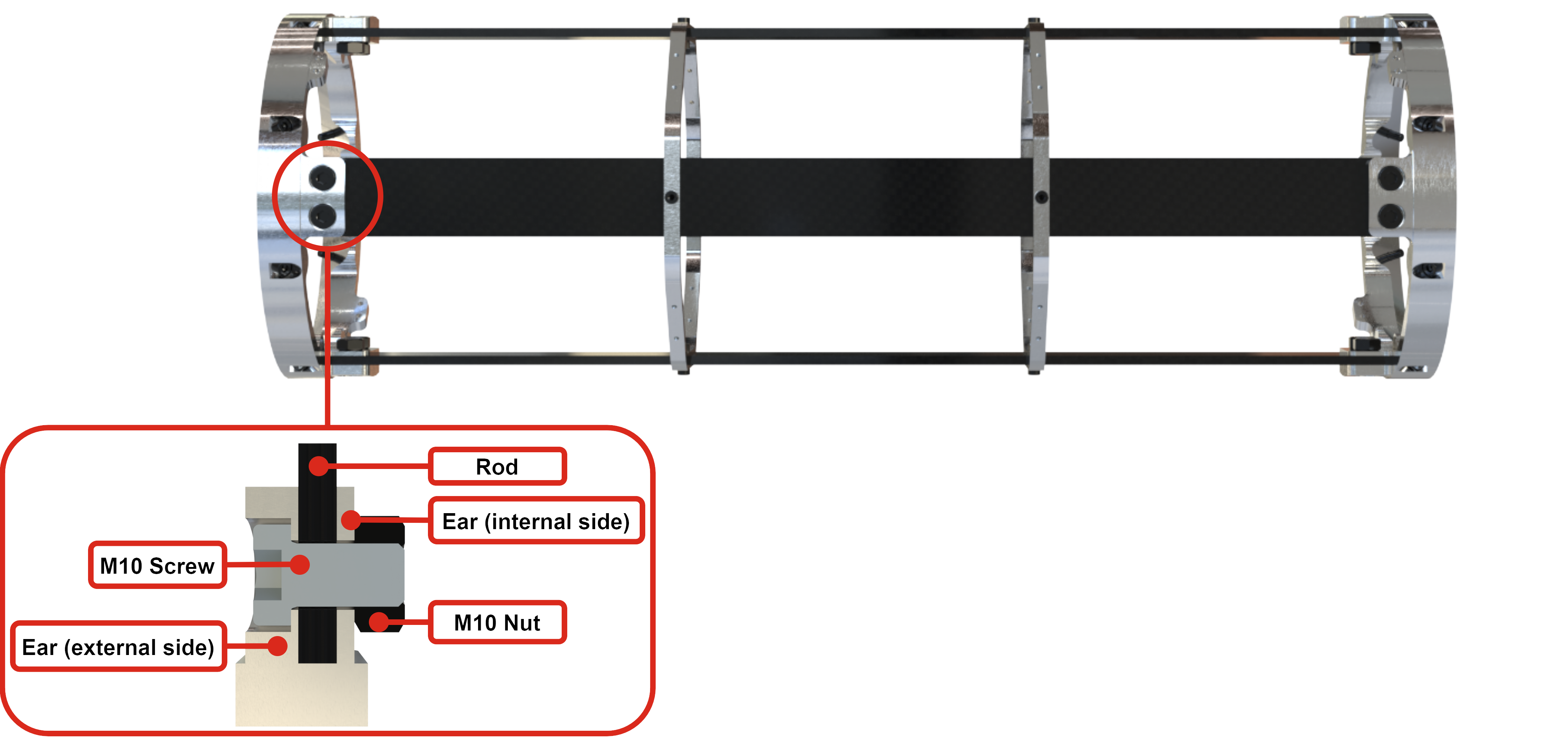
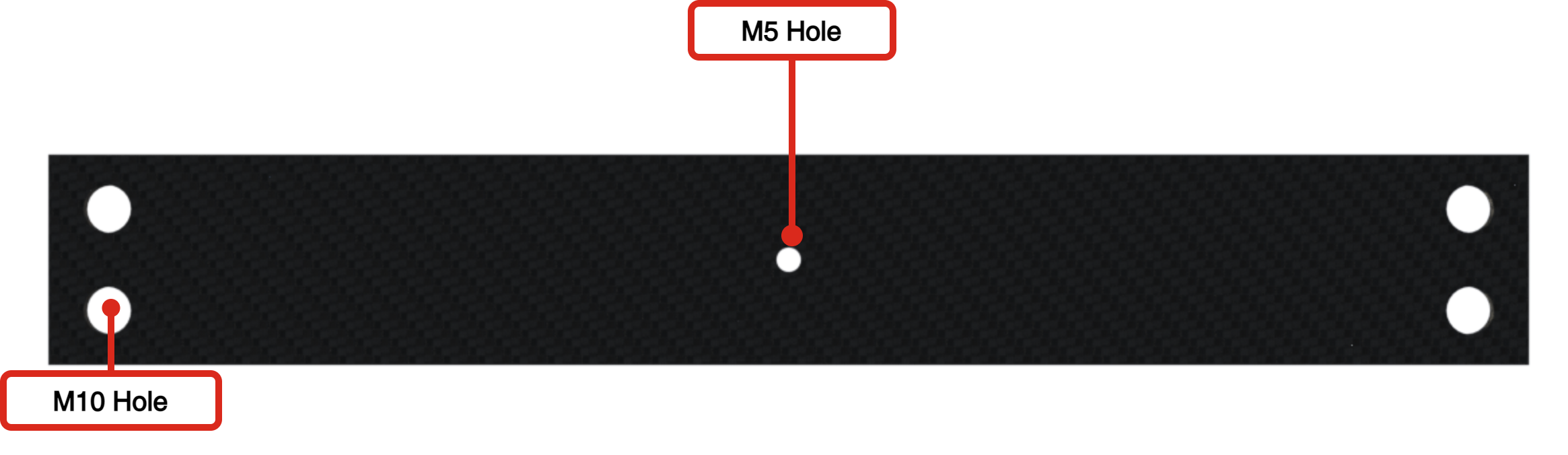
A CFRP rod similar to that used on the Avionics Bay will be used for the test. It has 2 M10 holes at each end for the ear screws and an M5 hole in the center for the ABR fastener.
¶ Ears
As explained in the document 2024_C_ST_INTERNAL-STRUCTURE-SCREWS_TR a first test was carried out on an ear identical to the one used in the rocket. But as the result was not satisfactory, a second test was carried out with other ear models.
Here is a list of the different ear models that have been tested
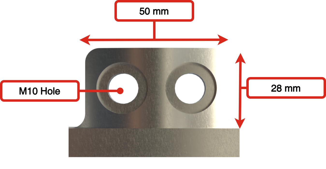
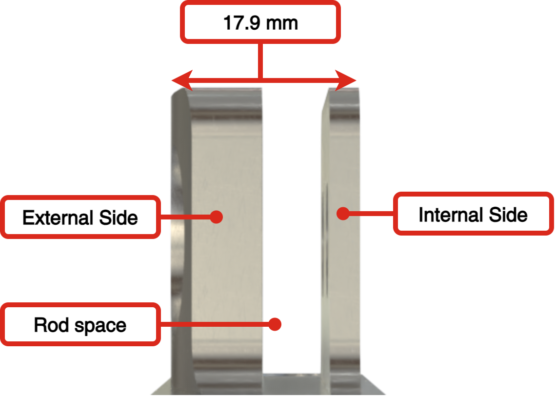
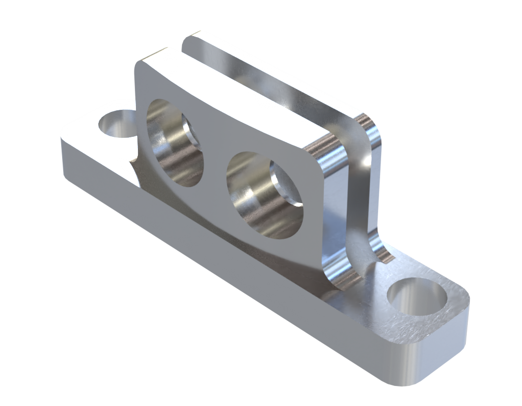
Named Classic Ear, this model is identical to the one used in the rocket. It consists of two surfaces attached to the same base and crossed by 2 M10 holes. The distance between these two surfaces corresponds to the average thickness of the rods.
 |
 |
|---|
 |
 |
|---|
Advantages
Produced in one part, makes assembly easier
Mass 71.5 [g]
Easy to assemble, only two screws
Disadvantages
The design makes it difficult to create a variety of surface finishes inside the ear, as there is little space for the tool.
A significant part of the screw's load goes through the deformation of the aluminum to tighten the rod.
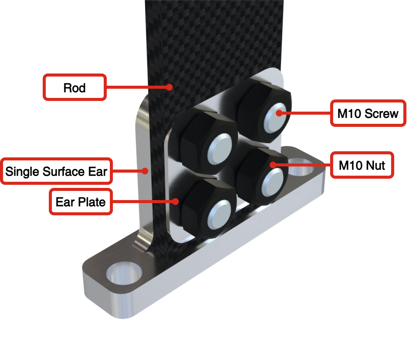
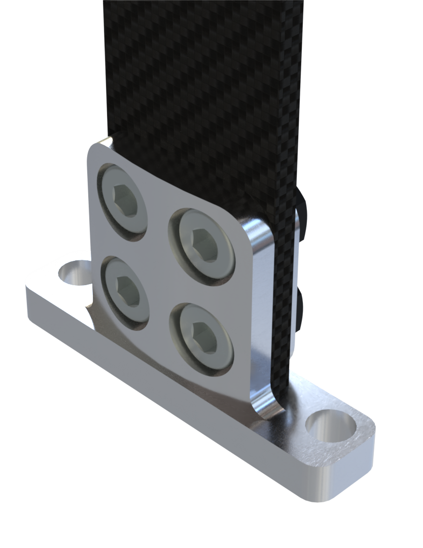
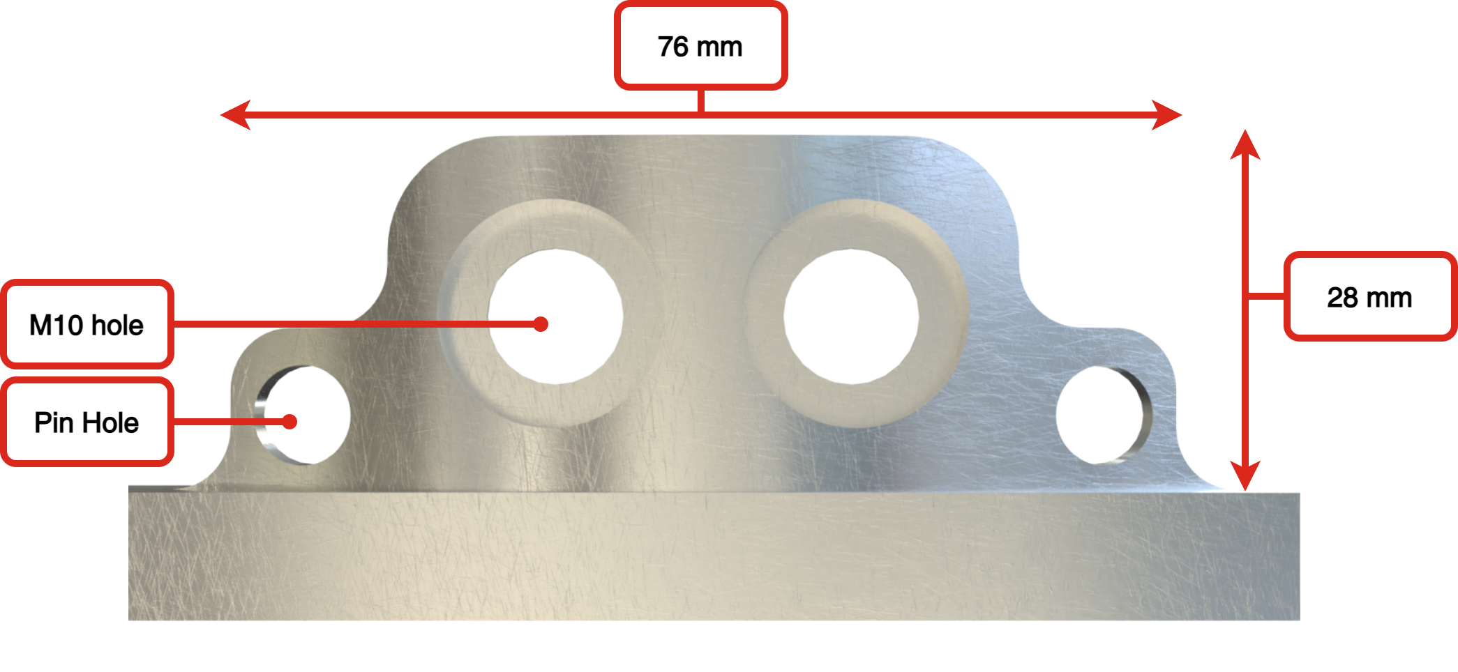
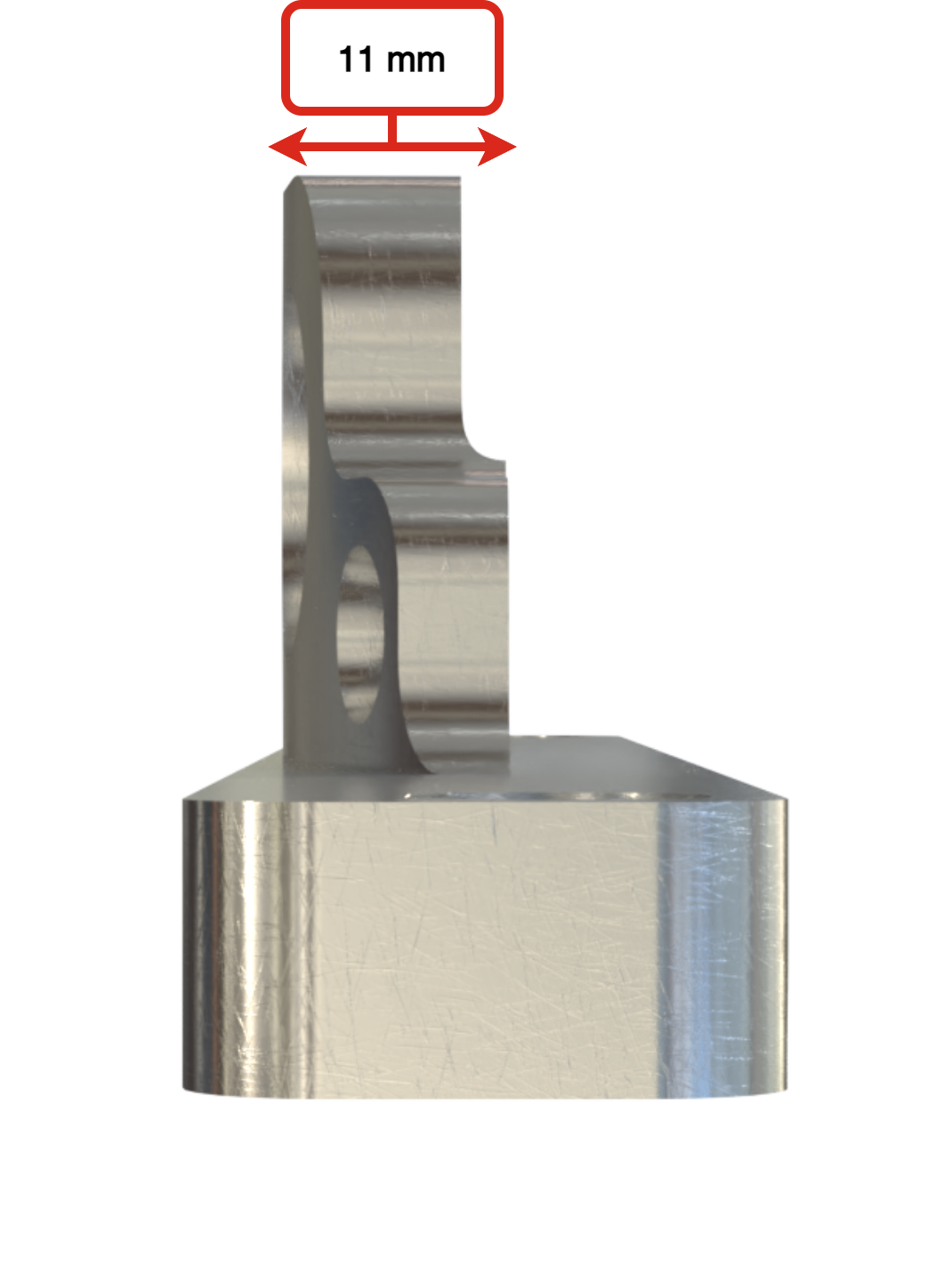
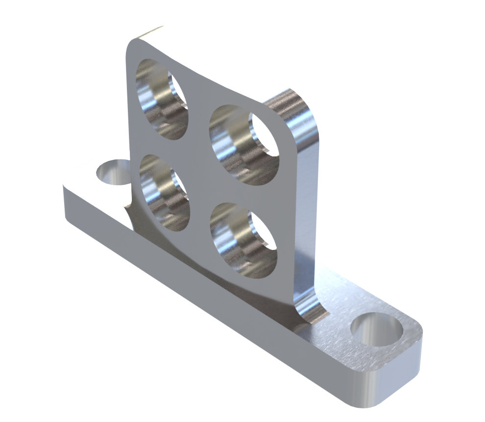
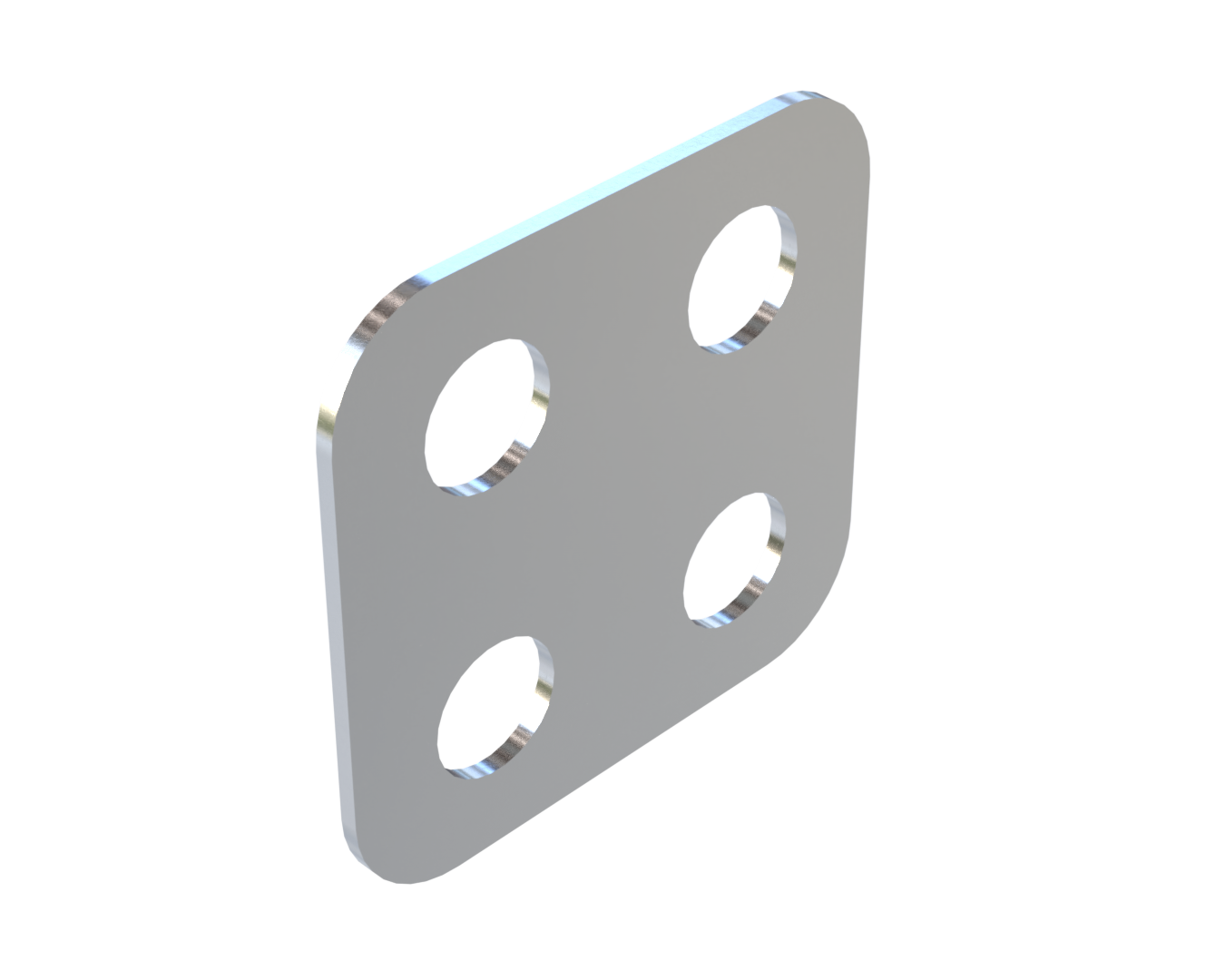
Named Single surface Ear, this model consists of a single surface but with 4 M10 holes. As the removal of a surface also removes a factor of 2 from the screw load calculation, twice as many screws are required. To avoid direct contact between the nuts and the carbon, a plate is placed between the two.
 |
 |
|---|
 |
 |
|---|
Advantages
Produced in one part
Is the simplest and fastest model to produce
Allows for a wide variety of surface finishes because the tool has plenty of space
Redundancy due to the number of screws
Disadvantages
Large geometry
Mass 157.8 g
Longer assembly time due to more screws
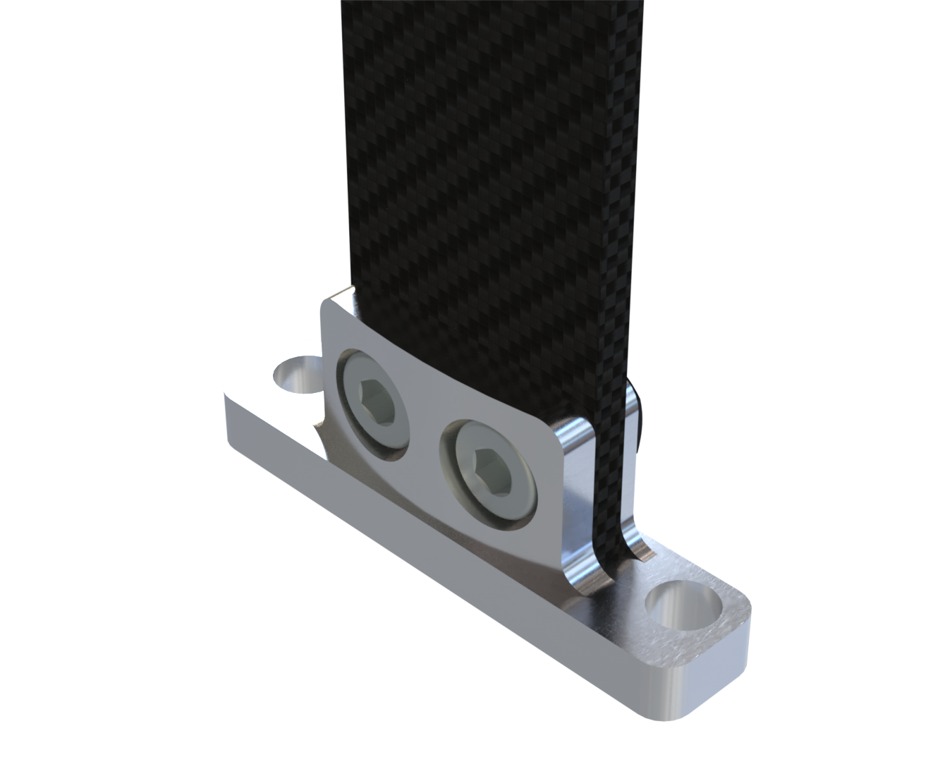
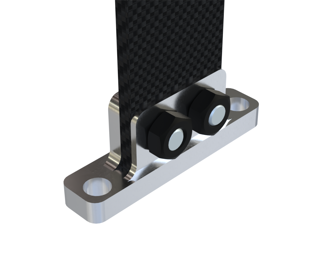
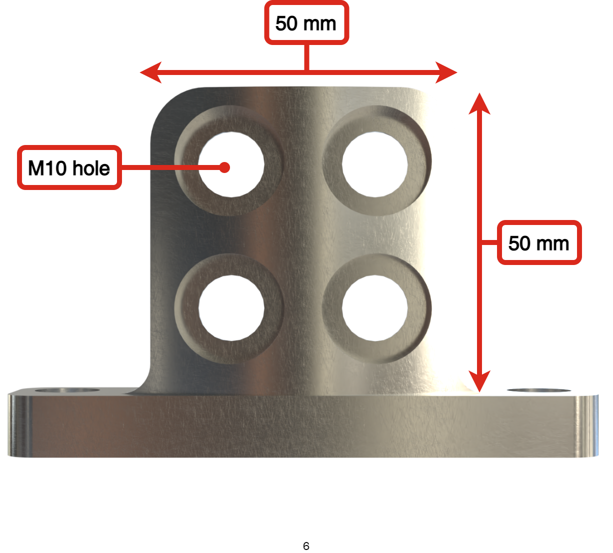
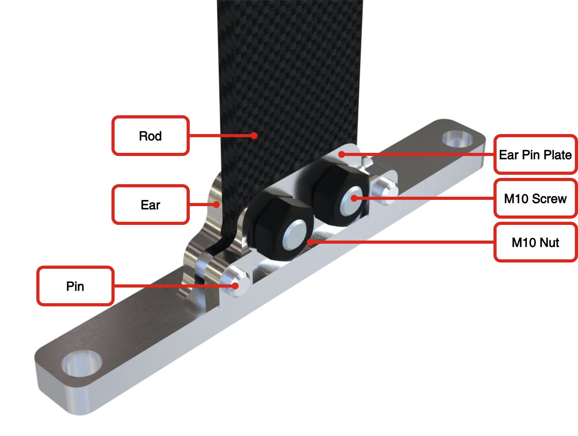
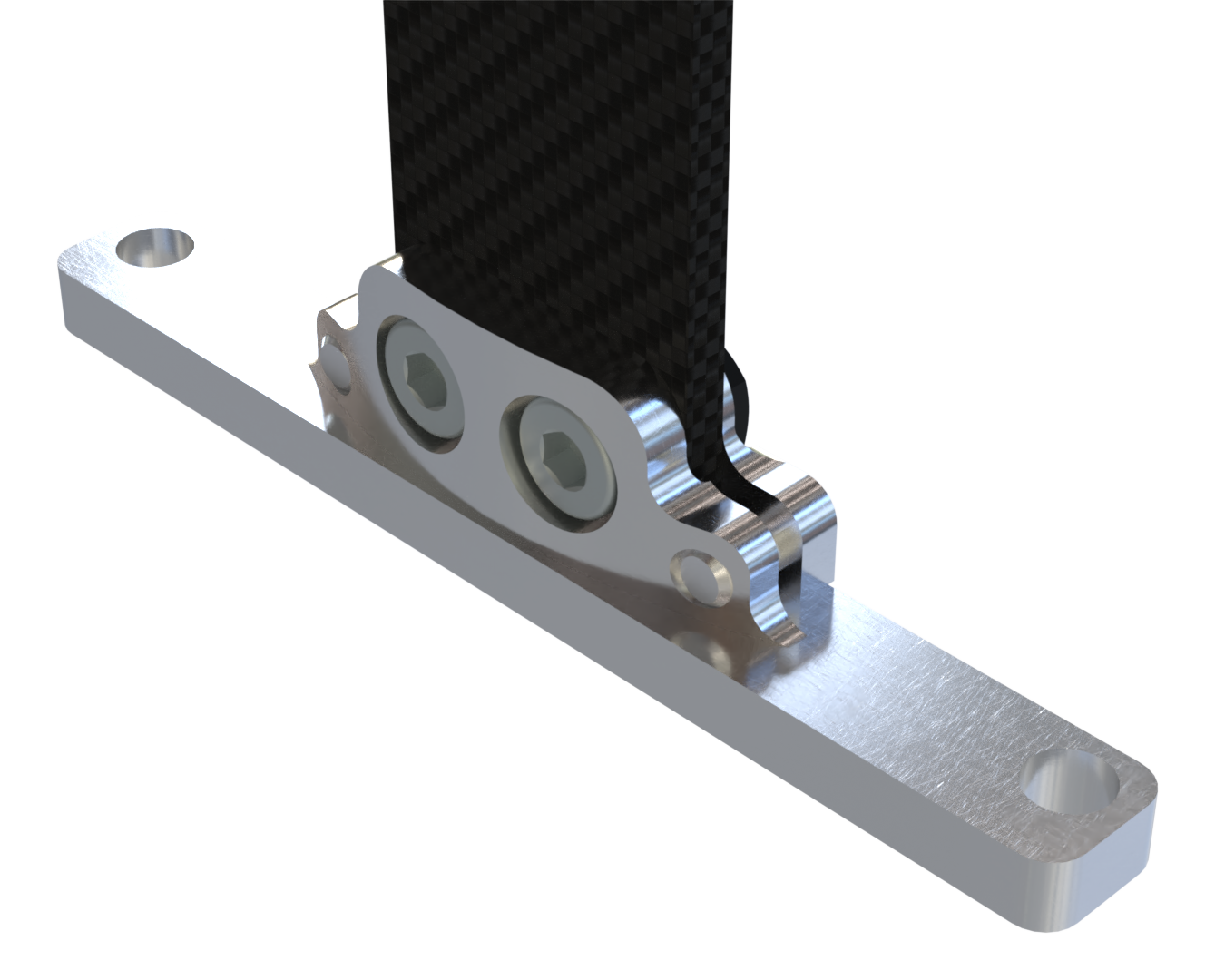
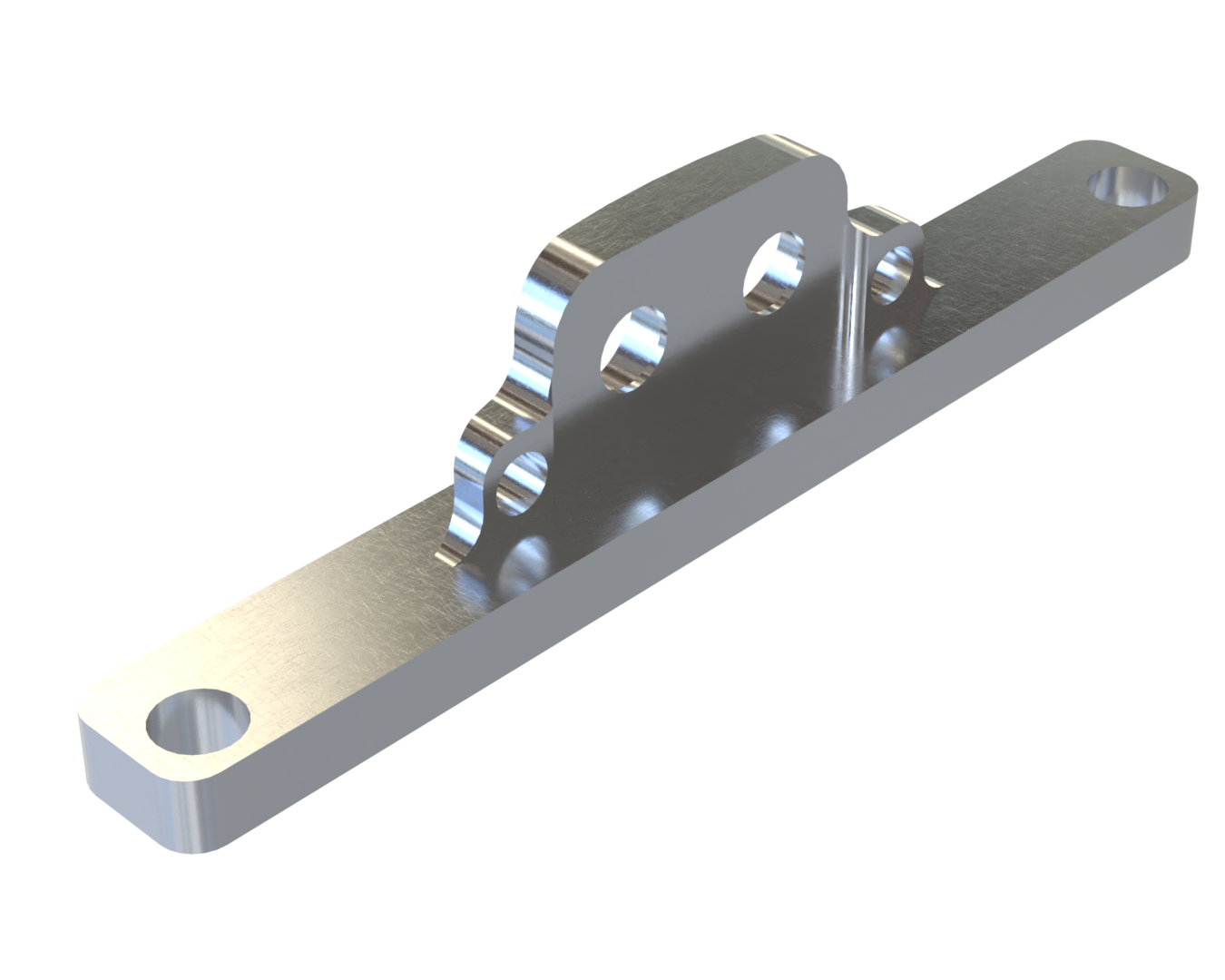
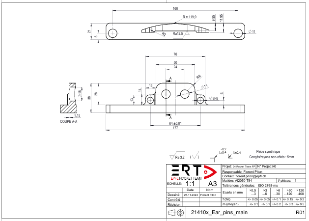
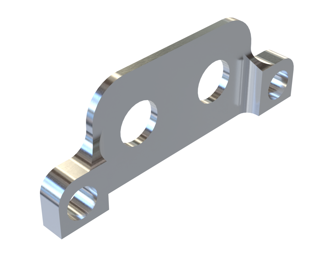
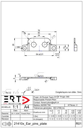
Named Ear Pins, this model consists of a single surface with 2 M10 holes but with two one pin on each side of the ear. These pins hold a plate to the main body. They also make it possible to slide the plate, so as not to lose any screw load in the deformation of the aluminum, compared to the classic ear.
 |
 |
|---|
 |
 |
|---|
Advantages
Allows for a wide variety of surface finishes because the tool has plenty of space
More optimal rod tightening than the Classic Ear
Disadvantages
More parts required than other models.
Produced in two parts, increasing production time.
Complex assembly due to pins
Mass 95.4 g
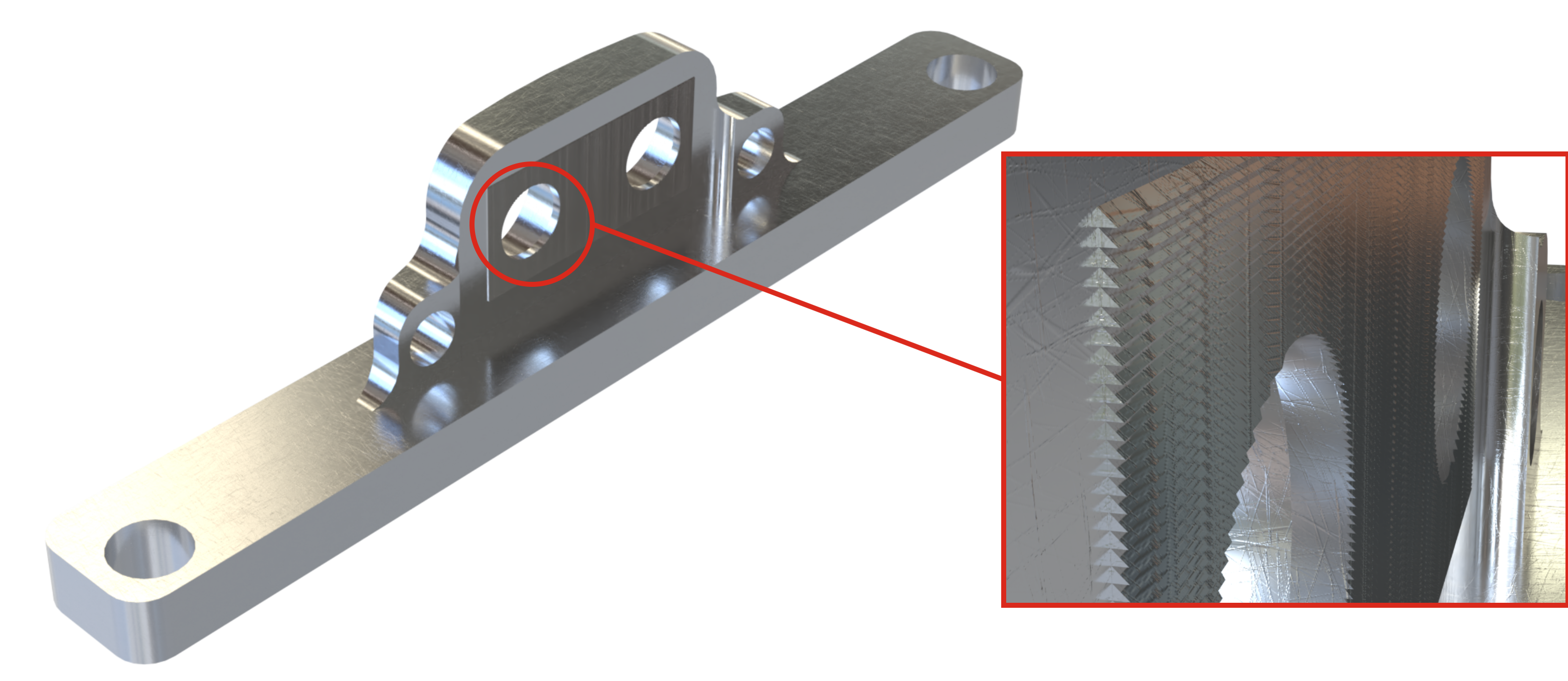
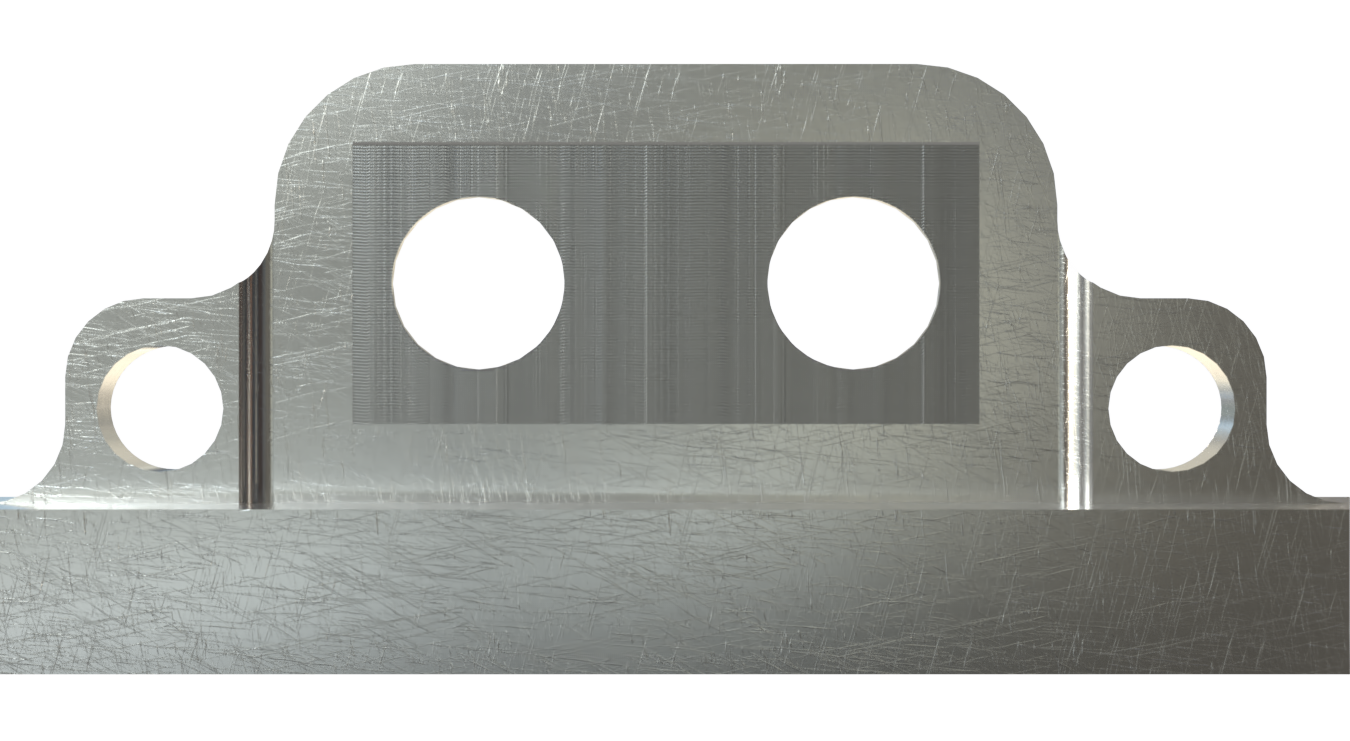
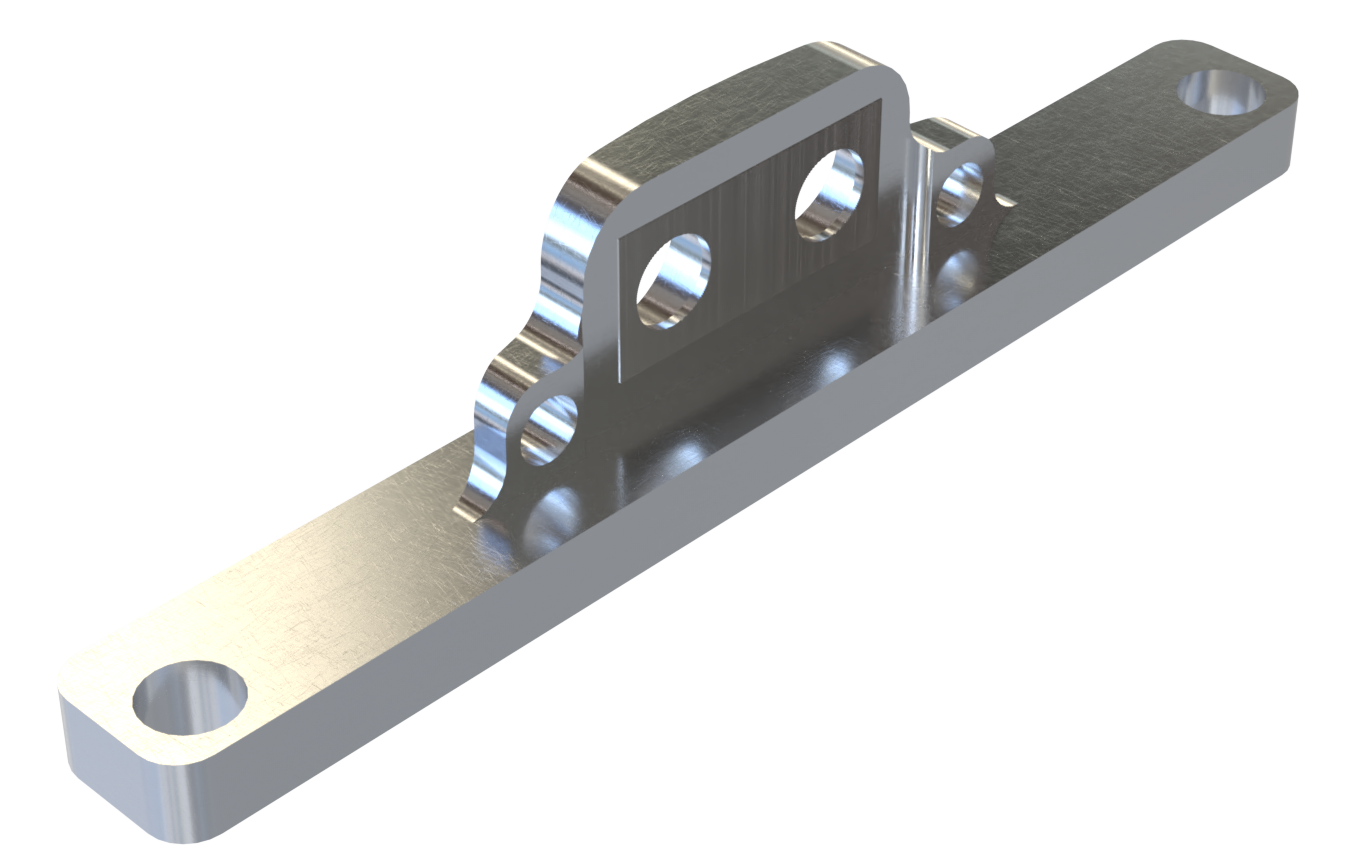
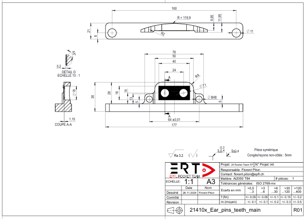
Named Ear Pins Teeths, This model is similar to the Ear Pins model, but has horizontal teeth on the inside of the ear. These teeth indent the first carbon layer to limit slippage.
 |
 |
|---|
Advantages
Allows for a wide variety of surface finishes because the tool has plenty of space
More optimal rod tightening than the Classic Ear
Disadvantages
Longer production times due to teeth
More parts required than other models.
Produced in two parts, increasing production time.
Complex assembly due to pins
Mass 95.4 g
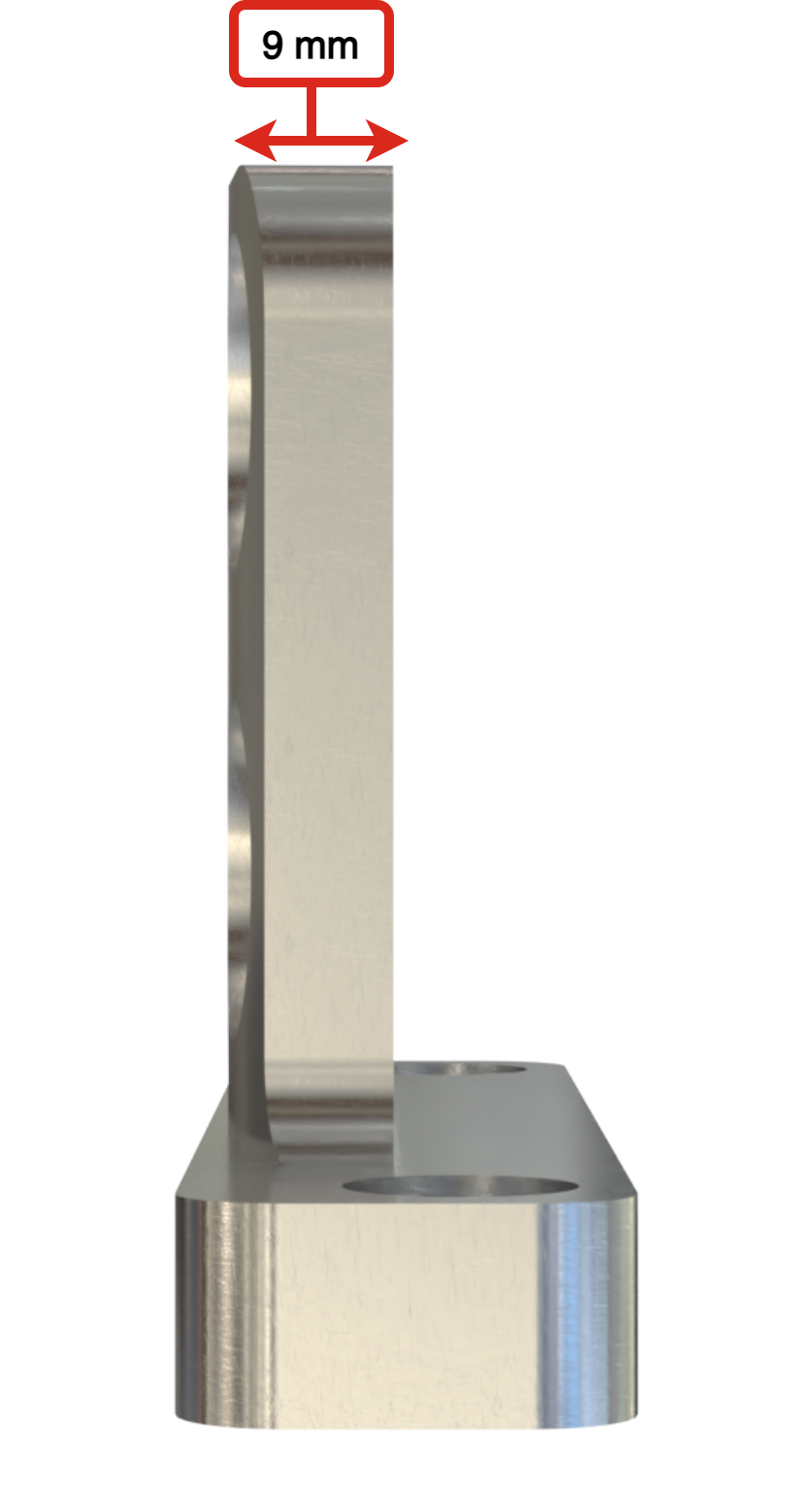
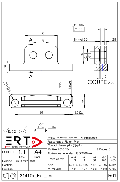
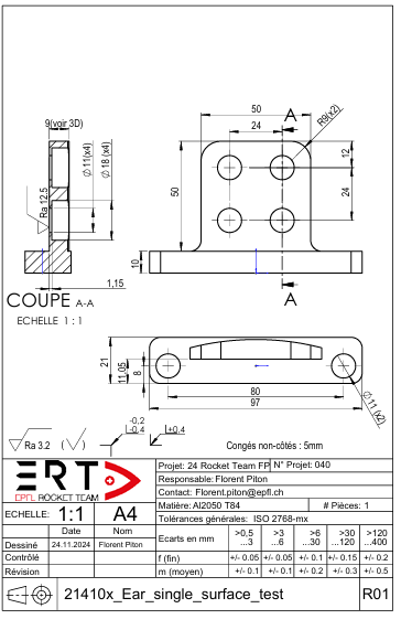
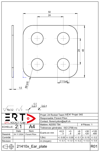
¶ Technical drawing
 |
 |
|---|
 |
 |
|---|
 |
 |
|---|
 |
 |
|---|
 |
 |
|---|
 |
 |
|---|
¶ Fasteners
| Part Name | Number of Parts | Main Characteristics | Link to Data Sheet/ DDF |
|---|---|---|---|
| Ear screw | x2 - x4 | M10x18 screw with grade 10.9 | M10_screw_Datasheet |
| Ear nut | x2 - x4 | M10 nut with grade 12 | M10_Nut_Datasheet |
¶ Test Methods
To avoid any impurities or grease that could impact the test, carbon and aluminum surfaces must be handled with latex gloves and cleaned with alcohol before the start of the test.
The rod will be placed inside the Ear, then the torque previously calculated will be applied to the screws using a torque wrench. A mark will be made on the sides of the ear to observe any displacement. The rods will then be subjected to tensile loading.
For the first test, the Torque applied is 45 [Nm] as calculated in 2024_C_ST_INTERNAL-STRUCTURE_DDF.
For the second test, the torque applied is 70 [Nm] as determined in 2024_C_ST_INTERNAL-STRUCTURE-SCREWS_TR
¶ Environment
No specific conditions are required except it has to be done in a laboratory equipped with the necessary equipment to perform such a test.
¶ Data and Scenarios
The data extracted from the traction testing machine will be a curve of the displacement as a function of the force applied. The curve of each ear model will be compared on the same graph.
¶ Tools
- 1 Torque Wrench
- Caliper/Micrometer
- LATEX Gloves
- Cleaning alcohol
- Traction testing machine
¶ Pass/Fail Criteria
No displacement of the rod inside the ear with a load of 33[kN]
No ear deformation
No cracks
The sample didn't slip inside the grips
Rupture before the required force
Crack or delamination
Slipping inside the grips
Displacement of the rod inside the Ear
¶ Test Procedure
The procedure is the same for all ear models.
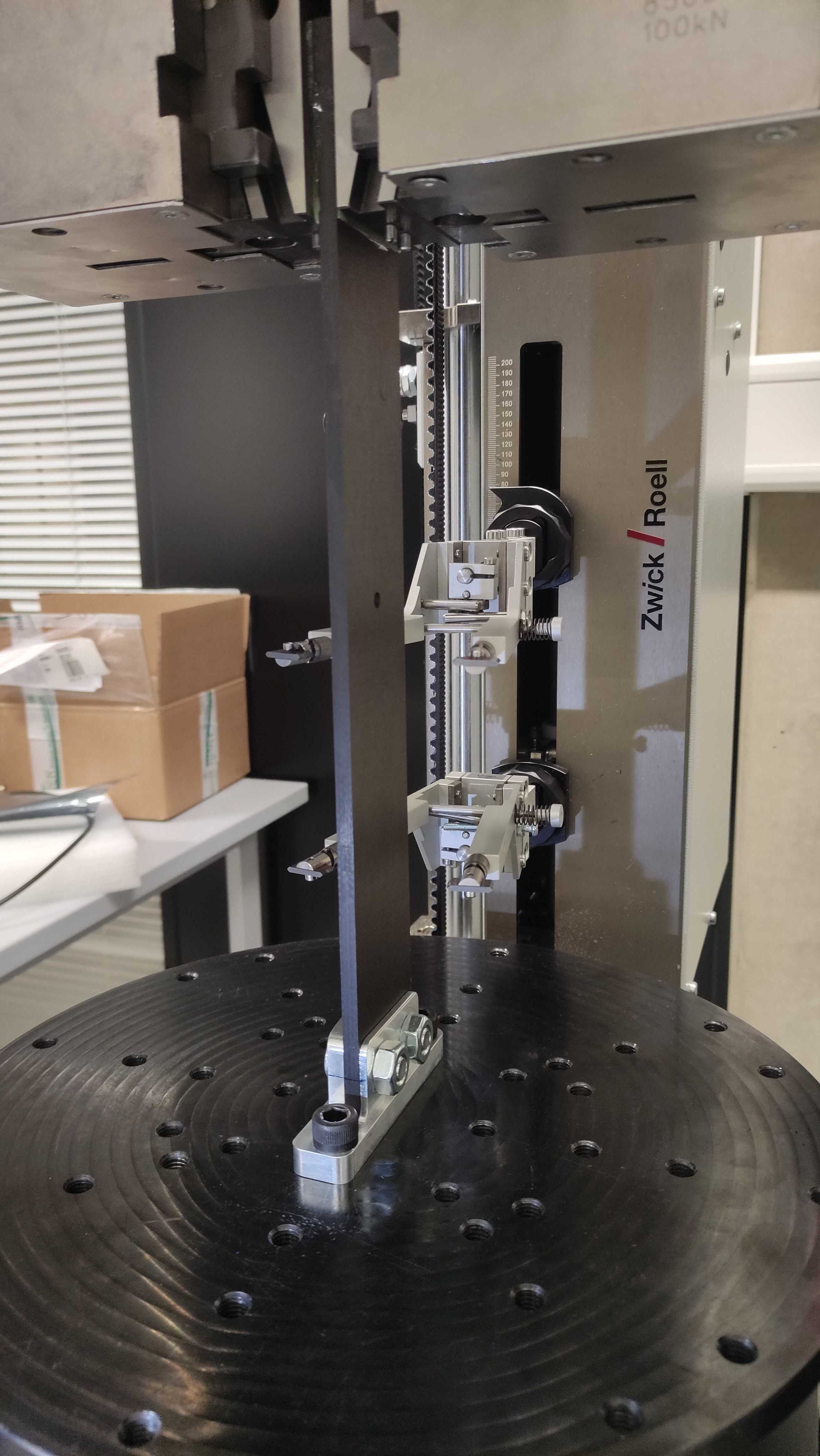
¶ Test Set-up
The ear is screwed to a support compatible with the traction testing machine. At the top the rod is held by the grips.
¶ Test Equipment Checklist
| Check | Quantity | Equipment |
|---|---|---|
| 4 | CFRP Rod 350[mm]x50[mm]x6.11[mm] with the 13[mm] holes | |
| 1 | Classic Ear | |
| 1 | Single Surface Ear | |
| 1 | Ear Plate | |
| 1 | Ear Pins | |
| 2 | Ear Pins Plate | |
| 1 | Aluminium Ear | |
| 1 | Ear Pins Teeths | |
| 10 | M10x18 screws | |
| 10 | M10 nuts | |
| 2 | M10x25 screws | |
| 1 | Torque Wrench 20 - 100 Nm | |
| 1 | Socket box | |
| 1 | 17" key | |
| 1 | Cleaning alcohol bottle | |
| 1 | Clean cloth | |
| 1 | Glove box | |
| 1 | Marking tip | |
| 1 | Black marker | |
| 2 | GFRP tabs 50[mm]x56[mm]x1.5[mm] | |
| 1 | Caliper |
¶ Test Instrumentation Description
The Zwick 100kN Tensile Test Machine will provide all the data necessary.
The extensometer is also directly linked to the testing machine.
¶ Test Safety
| Safety Concern | Probability | Impact | Severity | Mitigation | Post-Mitigation Probability | Post-Mitigation Impact | Post-Mitigation Severity | Corresponding Action Item | Action if safety Concern still occurs |
|---|---|---|---|---|---|---|---|---|---|
| Rupture of the sample | Low | Can project fibers | Medium | Wear appropriate PPE in case of rupture | Low | Low | Low | PPE |
¶ Risk Analysis
| Risk | Probability | Impact | Severity | Mitigation | Post-Mitigation Probability | Post-Mitigation Impact | Post-Mitigation Severity | Corresponding Action Item | Action if safety Concern still occurs |
|---|---|---|---|---|---|---|---|---|---|
| Apply less torque than required to screws | Medium | Can gives unrelevant results | high | Calculate the right torque | Low | Low | Low | Use a torque wrench |
¶ Tasks and Step-by-Step Procedure
| Done ? | Step | Tool |
|---|---|---|
| Clean the rod and the ear with alcohol | - | |
| Insert the end of the rod in the aluminum ear | - | |
| Insert the M10x18 screws inside the ear. | - | |
| Make sure that the rod is well placed in the ear | - | |
| Alternaly tighten the screws to the required torque | - | |
| Tighten the ear to the machine with 2 M10x25 screws | - | |
| Place the rod end with tabs inside the machine | - | |
| Inspect the system before starting test | - | |
| Applied 33kN with displacement control of 2 [mm/min] | - | |
| Verified by inspection on the ear and on the graph the rod displacement | - |
¶ Comments
For the first test, two GFRP tabs were glued to the top of the rods as specified in ASTM 3039. Due to lack of time and fiberglass, the second test was carried out without the tabs bonded to the rods.