¶ Introduction
¶ Purpose, Objective and Scope
This document is separated into two sections, the test specification and the test procedure.
The test specification section defines the purpose of the test, the test approach, the item under test, test sequence, test facility, pass/fail criteria, required documentation, participants and test schedule.
The test report section gives directions for conducting a test activity in terms of description, resources, constraints and provides detailed step‐by‐step instructions for conducting test activities with the selected test facility and set‐up.
This document covers the preparation and the procedure for carrying out tensile tests for polymer matrix composite materials, in order to determine their mechanical properties in traction.
In particular, it focuses on the tensile tests for the CFRP rods of the internal structure.
It provides the guidelines to the person performing such tests.
It covers the testing protocol as well as the different points of analysis.
It does not cover the actual analysis of the results, neither the test report.
¶ Test Documentation
There are 3 main types of documents which relate to testing activities.
¶ AI&T
- High level overiew of testing activities
- Highlights dependancies in between types of tests
- Tracks the status of each type of test
- Document should be prepared as early as possible after PDR
¶ TSP
-
Test specification section explains:
- What part/assembly is being tested during each test.
- What characteristic is being tested.
- Brief description as to how the test is goind to be conducted.
- Explains the Pass/Fail criteria for each step.
- Explains when the test is due to happen and who will be involved in the test.
-
Document should be prepared after the baseline AI&T and ~1 month before the actual test.
-
Test procedure serves as a detailed plan for each individual test, it contains (among other things):
- A list of tools and instrument needed for the test.
- A description of the test location and condition.
- A step by step procedure of what needs to be done before, during and after the test.
-
Document should be prepared after the test specification and at least ~1 week before the actual test.
¶ TR
- The test report contains:
- The "as run procedure", meaning the procedure as planned ~1 week before the test with all of the comments and modiciations which were done the day of the test.
- The results of the test and all of the test data (or at least a link to the test data).
- If applicable, the analysis of the test data.
- The conclusion.
- The baseline document should be prepared the day of the test and the final version should be ready ~1 week after the test
¶ Definitions and Abbreviations
- ST : Structure
- FoS : Factor of Security
- ERT : EPFL Rocket Team
- CFRP : Carbon Fiber Reinforced Polymer
- GRP : Glass Reinforced Plastic
- FEA : Finite Elements Analysis
¶ Applicable and Reference Documents
- ASTM D3039 Tensile Tests
- 2024_C_ST_INTERNAL-STRUCTURE_DDF
- 2024_C_ST_ROD_FEA_2
- 2024_C_ST_CFRP-PLATE_MAP
¶ Requirements to be verified
- 2024_C_SE_ST_REQ_33 Load Case - Axial deceleration
The structural load-bearing elements shall withstand axial tension of [132000]N.
¶ Test Specification
¶ Open issue, Assumption and Constraint
The rods used for Firehorn includes holes that are not present on the test samples. Since the stress increases near holes, it will be necessary to apply a force higher than the minimum force required to verify that the rods support the flight loads.
¶ Test Description
This test follows ASTM D3039 standard.
Objectives:
This test is performed to verify that the rods can withstand the tensile loads subjected to them during flight. At the same time, it will give an estimation of the Young's modulus of the CFRP plate manufactured for the rods.
Method:
Multiple CFRP samples will be subjected to a traction force of minimal magnitude equivalent to that experienced during flight. This will be done using a traction testing machine.
Environment:
No specific conditions are required except it has to be done in a laboratory equipped with the necessary equipment to perform such a test.
Data and Scenarios:
The data extracted from the traction testing machine will be a curve of the force applied as a function of the displacement. With the use of an extensometer, strain can be given too.
Tools:
- At least 5 rectangular CFRP samples (250[mm]x25[mm]x6.11[mm])
- Glass Reinforced Plastic of thickness 1.5[mm]
- Caliper/Micrometer
- Spirit level
- Traction testing machine
- Extensometer
¶ Test Sequence
No constraints on the testing activities sequence were identified.
¶ Pass/Fail Criteria
Resists a force of at least 16,5[kN] (constraint equivalent to 33[kN] in a rod)
Resists a force of 33[kN] (to ensure the resistance of the rods with holes)
No cracks
The sample didn't slip inside the grips
Rupture before the required force
Crack or delamination
Slipping inside the grips
The pass criteria of 16.5[kN] is due to the size of the cross section of the sample. Since the cross section of the sample is 25[mm]x6.11[mm] compared to 50[mm]x6.11[mm] for the actual rod, the force must be half as small on the sample to have a stress similar to what the rod will experience in flight.
A test at 33[kN] is still perform to ensure it resists higher stress since the holes in the rods will increase the stress near them.
¶ Test Organisation
This test will be performed by the students in charge of the composite testing semester project.
It will take place when the CFRP samples are cut and the GRP tabs are ready.
Location: DLL Materials
¶ Test Procedure
¶ Item Under Test
The rod tested here is actually a rectangular sample (250[mm]x25[mm]x6.11[mm]) from the same CFRP plate as the rods, prepared specially for this test.
| Sub-System | Part Name/ID | Type of Part | Version ID |
|---|---|---|---|
| Structure | 214101_Rod | Prototype | 12.09.24 |
¶ Test Set-up
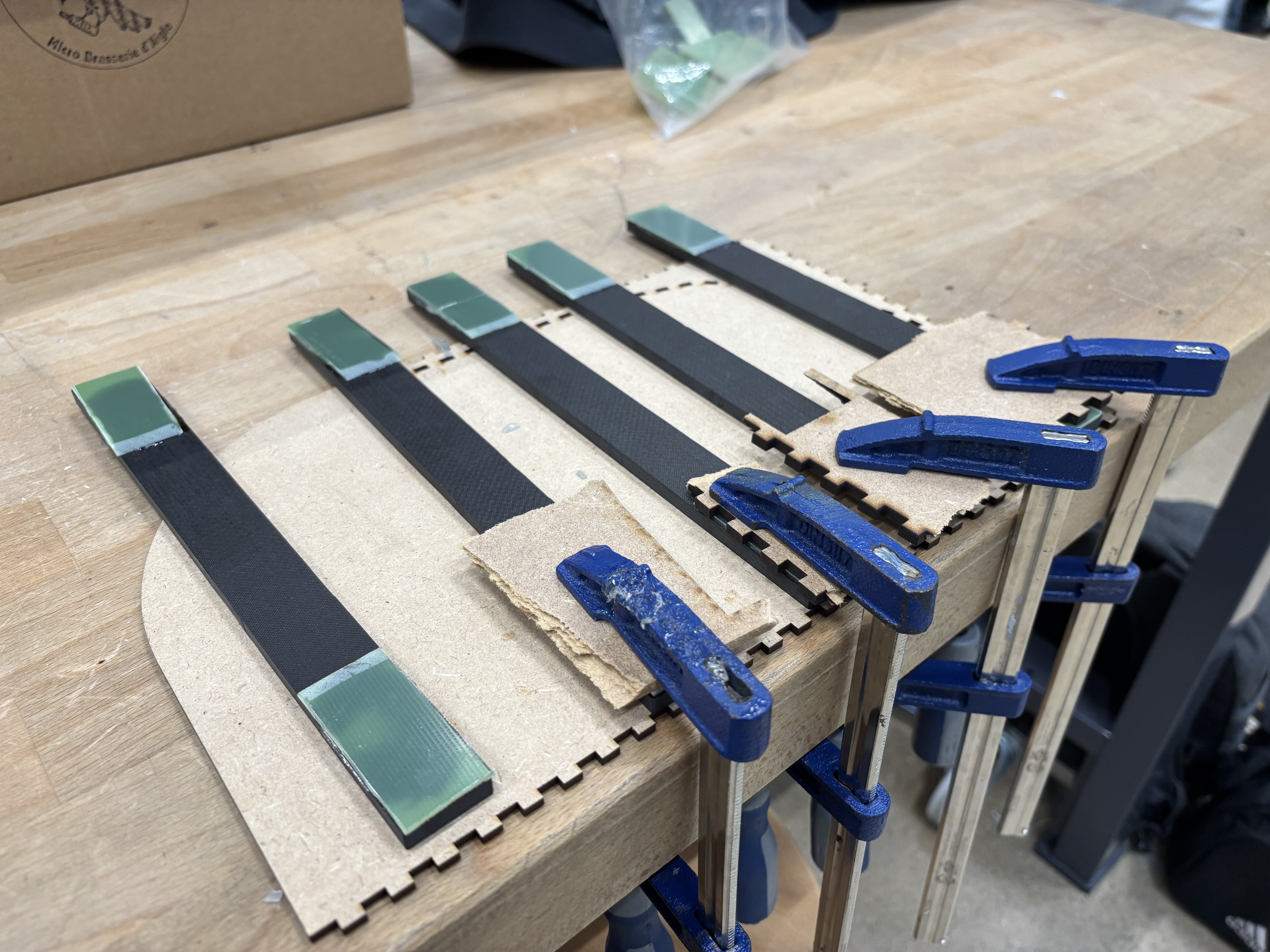
Before the tests, GRP tabs are glued with epoxy on both sides of the CFRP samples
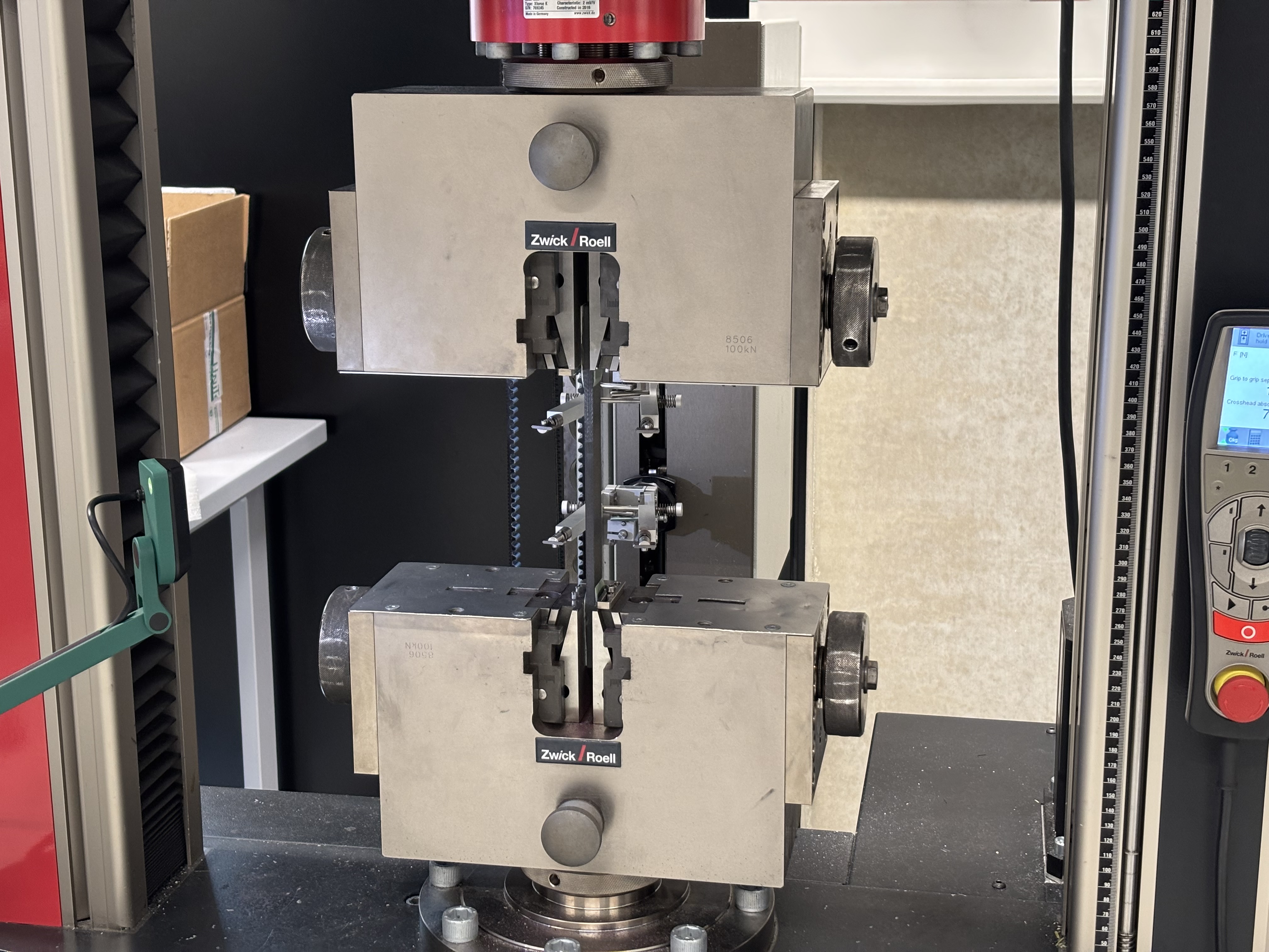
The sample is clamped inside the grips of the traction testing machine, with the GRP tabs in contact with the grips.
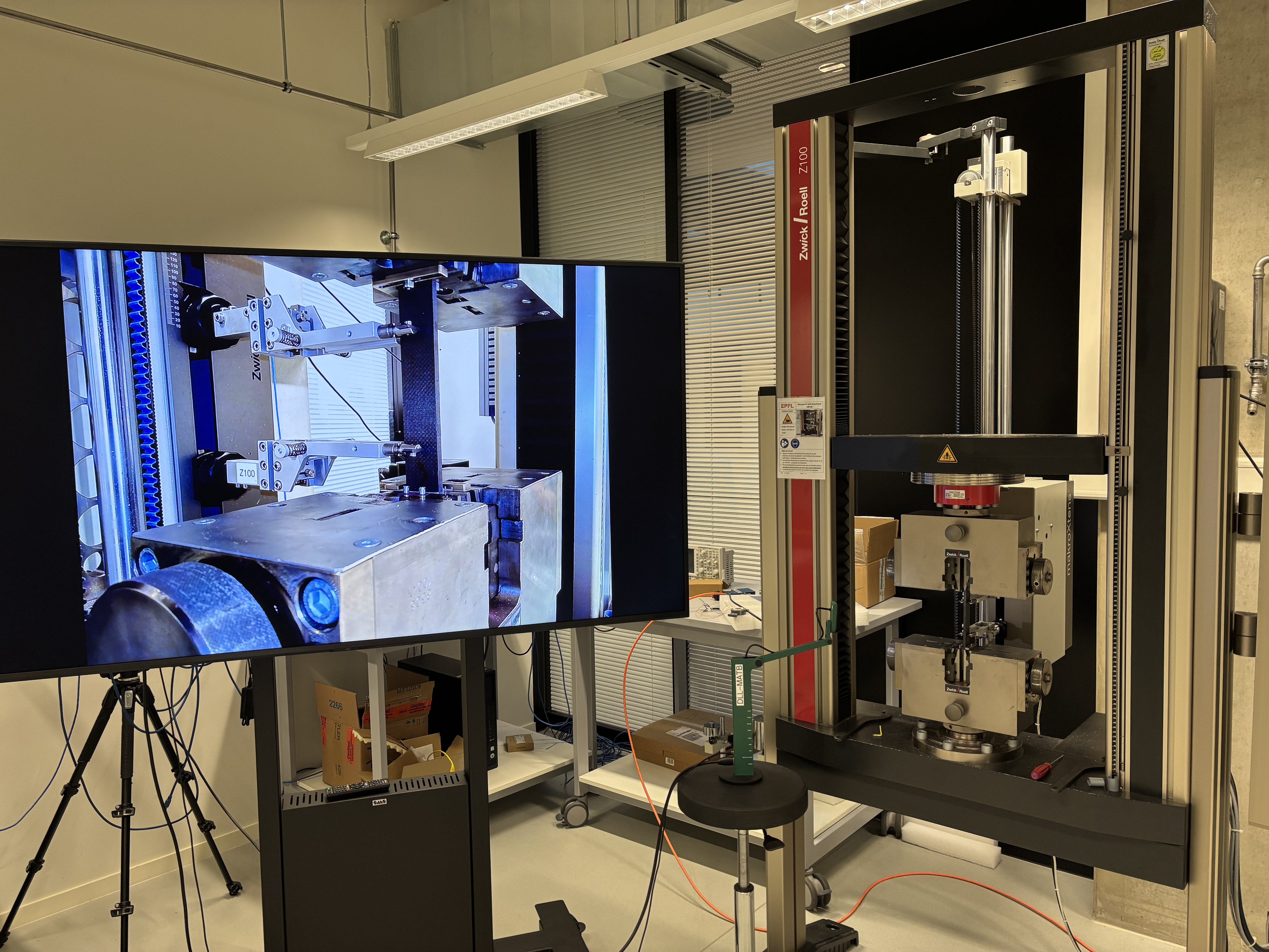
A camera is installed near the test sample.
¶ Test Equipment Checklist
| Packed ? | Equipment |
|---|---|
| CFRP samples | |
| GRP tabs | |
| Caliper | |
| Spirit level | |
| Protective glasses | |
| Camera | |
| Tripod | |
| Computer |
¶ Test Instrumentation Description
The Zwick 100kN Tensile Test Machine will provide all the data necessary.
The extensometer is also directly linked to the testing machine.
¶ Test Location and Conditions
The test is performed in room MED3 1523, with normal conditions.
¶ Test Safety
| Safety Concern | Probability | Impact | Severity | Mitigation | Post-Mitigation Probability | Post-Mitigation Impact | Post-Mitigation Severity | Corresponding Action Item | Action if safety Concern still occurs |
|---|---|---|---|---|---|---|---|---|---|
| Rupture of the sample | Low | Can project fibers | Medium | Wear appropriate PPE in case of rupture | Low | Low | Low | PPE | |
| Wrong use of the testing machine | Medium | High (can damage the machine) | High | Training on the machine | Low | High | Medium | Be careful to the setup and the correct completion of each step |
¶ Tasks and Step-by-Step Procedure
¶ Before Test
| Done ? | Step | Tool |
|---|---|---|
| Cut the CFRP plate in at least 5 samples of size 250[mm]x25[mm]x6.11[mm]. | - | |
| Check their condition and only keep those free of any defects (scratches, cracks, etc.) | - | |
| Protect them before the test. | - | |
| Cut the GRP plate in at least 20 tabs (4 for each sample) of size 50[mm]x25[mm]x1.5[mm] | - | |
| Cut one end of each tab such that there is a surface with an angle between 7° to 10°. (see ASTM D3039 for dimensions) | - | |
| Protect them before the test. | - | |
| Do the training at DLL Materials on the Zwick 100[kN] | - | |
| Prepare the equipments needed (caliper, spirit level) | - | |
| Prepare PPE (if needed) (most likely glasses) | - | |
| Know where the first kid aid is and have a phone ready for emergency | - |
¶ During Test
| Done ? | Step | Tool |
|---|---|---|
| Weight the sample | - | |
| Measure precisely its length, width and thickness | - | |
| Measure its cross-sectional area at three different places in the gage section and report this area as the average of these three measurements | - | |
| Glue two tabs at each end of the sample with the inclined surface directed to the gage section | - | |
| Install the sample in the grips | - | |
| Check with the spirit level that it is perfectly vertical | - | |
| Tighten the grips as much as possible to prevent any slippage during the test | - | |
| Correctly install the extensometer. The gage length should be between 10[mm] and 50[mm]. | - | |
| Setup the machine. If it is a strain controlled test, the strain rate should be 0.01[min^(-1)]. If it is a constant head-speed test, the head displacement rate should be of 2[mm/min] | - | |
| Run the test, watching its progress carefully and being ready to stop it if something unexpected happens | - | |
| Save the data given by the testing machine | - | |
| Repeat this for all the other samples | - |
¶ After Test
| Done ? | Step | Tool |
|---|---|---|
| Mark and take a picture of any damage on each sample. This could be cracks, delamination, etc. Report their location on the sample | - | |
| Analyze the results by calculating the density of each sample and estimating the Young's modulus | - |