¶ Goal(s) of the study
These simulations were performed in order to check that the rods withstand flight loads.
¶ 214101_Rod
¶ Geometry
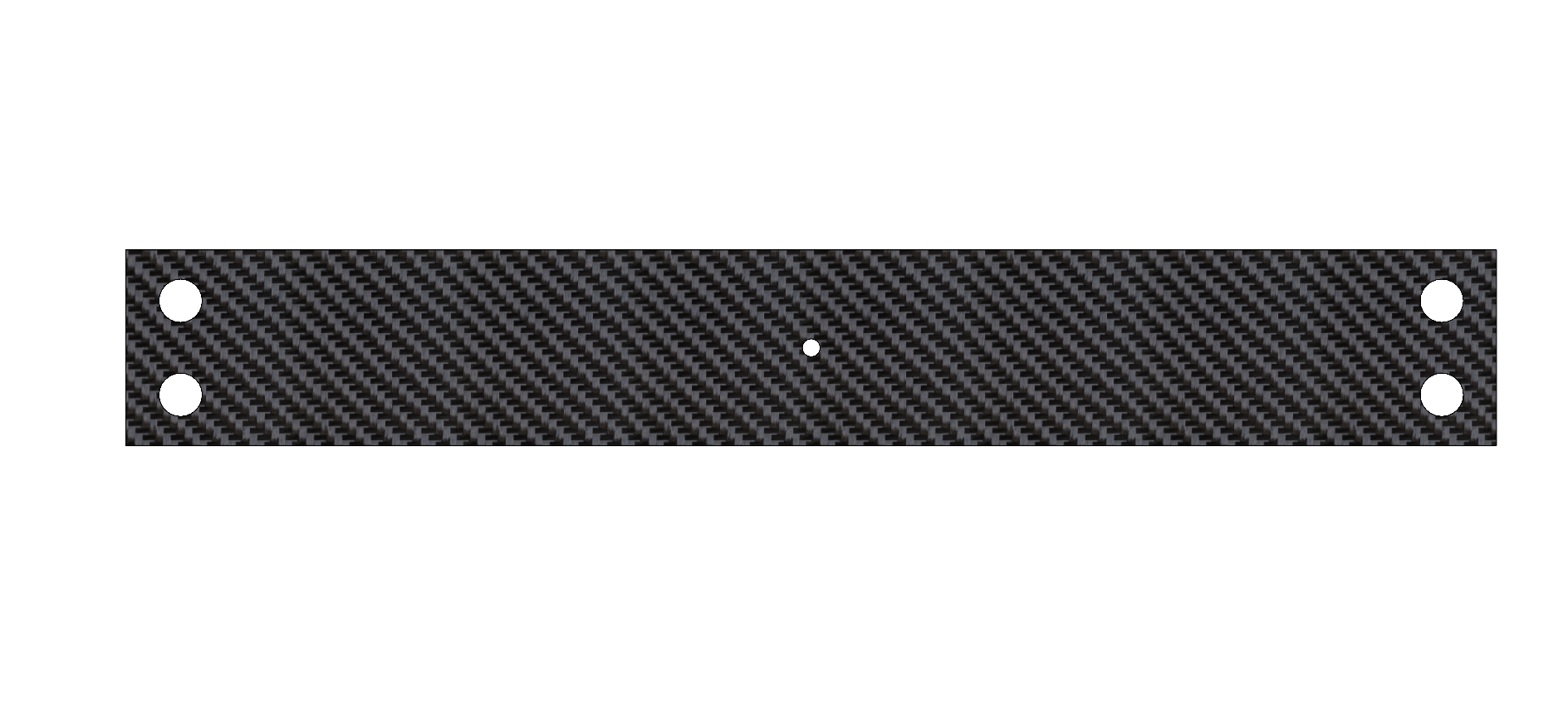
The geometry used is a rod of 350[mm]x50[mm]x6.11[mm].
¶ Function
The rods, essential parts of the internal structure of the rocket, must ensure structural integrity of the rocket and supports all loads applied to it.
¶ Material
The rods are made of CFRP whose layup is described in 2024_C_ST_CFRP-PLATE_MAP
¶ Load case
The rods must withstand the loads applied to the rocket. This analysis focuses on traction load case, which is caused by parachute deployment.
- 2024_C_SE_ST_REQ_33 Load Case - Axial deceleration
The structural load-bearing elements shall withstand axial tension of [132000]N. - 2024_C_SE_ST_REQ_37 Margins of safety for simulation validation
Unless specified otherwise, all parts shall be designed to withstand their design load with an additionnal Margin of Safety (relative to the elastic limit or other applicable failure criterion) depending on the part's nature: MoS 0.25 for all static simulations, MoS 3 for all buckling load cases, MoS 3 for all parts designed via generative algorithms.
¶ Finite Element Analysis
¶ Software
- ANSYS Mechanical
¶ Type of simulation
- Static structural
¶ Inputs
mmNS mm-ton-N-Nmm-MPa-mm^4-mJ
Only one rod is considered for this analysis, with different holes for the ABR and coupler screws.
The CFRP properties have been defined using ACP.
The properties for the UD and woven plies are:
| Material | Density (g/cm^3) |
|---|---|
| UD | 1.47 |
| Woven | 1.49 |
| | Elastic (Engineering constants) |||||||||
| Material | E1 | E2 | E3 | Nu12 | Nu13 | Nu23 | G12 | G13 | G23 |
|---|---|---|---|---|---|---|---|---|
| UD | 137000 | 10500 | 10500 | 0.3 | 0.3 | 0.51 | 5200 | 5200 | 3476.82 |
| Woven | 49000 | 49000 | 10000 | 0.05 | 0.35 | 0.35 | 5000 | 4500 | 4500 |
In ACP, the layup from 2024_C_ST_CFRP-PLATE_MAP was defined, which gave the following properties for the CFRP rods using an orthotropic model:
| Density (g/cm^3) | E1 | E2 | E3 | Nu12 | Nu13 | Nu23 | G12 | G13 | G23 |
|---|---|---|---|---|---|---|---|---|
| 1.5 | 88074 | 17739 | 10000 | 0.3 | 0.3 | 0.3 | 5000 | 4081.6 | 3192.2 |
- Static simulation
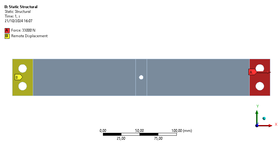
One end of the rod is fixed using remote displacement. Remote displacement is setup such that all degrees of freedom are fixed and the origin is in the middle of the surface where it is applied and between both surfaces to avoid rotation. Remote displacement is used here instead of just a fixed support to have converged results where the rod is fixed.
At the other end of the rod, 33kN is applied in traction, distributed on both sides.
|:--- :---
:---
| Real case | Model |
| Clamped between ears | Fixed |
This simulation is a static structural simulation. Non-linearities are not considered here, large deflections neither.
¶ Mesh
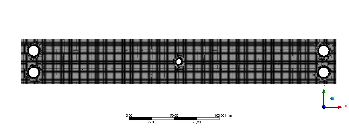
The geometries are 3D solid, so element shape is hex with a quadratic order.
A global mesh size is defined on the whole rod. Moreover, since the results doesn't converge near the holes for the screws, an edge sizing with a refinement of 2 is applied on the edges of the holes.
The covergence criteria for this simulation are the maximum equivalent stress and the minimum Tsai-Wu safety margin.
|:---:---:---:---:---
|Size|5|2.5|1|0.5|0.25|0.1|
Maximum equivalent stress [MPa]|426.83|364.04|546.79|779.08|764.93|771.22|
Deltas [%]|/|-14.71|50.20|42.48|-1.82|0.82|
Minimum safety margin|11.048|0.9374|0.4353|-0.0626|-0.27695|-0.71981|
Deltas [%]|/|-91.51|-53.56|-114.39|342.21|159.91|
At 1[mm] the global mesh is good enough for the whole rod, however the results at the screw holes did not converge. The lower mesh sizes are only for the edge sizing at the holes.
For a mesh size of 0.25[mm] and 0.1[mm], the maximum equivalent stress converges, but not the minimum safety margin. This is due to the screw holes. The safety margin doesn't converge there so it keeps varying when changing the mesh size.
Since an edge sizing of 0.25 or 0.1[mm] give approximately the same results, we will use a main mesh size of 1[mm] on the whole rod with an edge sizing of 0.25[mm] on the edges of the screw holes and a refinement of 2 at the same locations.
¶ Outputs
The equivalent stress obtained for this load case is as follows:
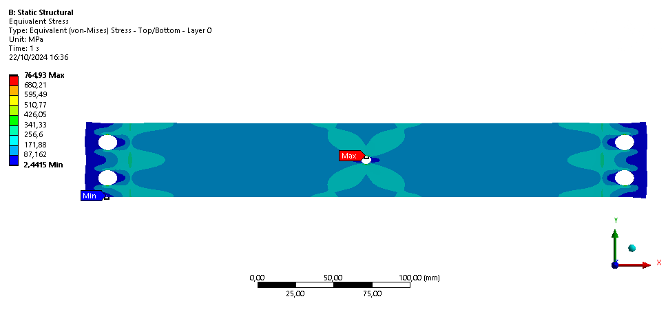
We can see that the stress is not that high in the entire rod, reaching not more than 400[MPa]. Higher stresses are encountered at the edge of the screw holes, where the results did not converge.
A closer look at the stress at the hole is shown below.

The margin of safety was computed using the Tsai-Wu criterion. To comply with the requirement, it shouldn't be below 0.25.
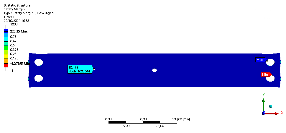
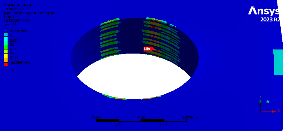
On these pictures, the Margin of Safety is below 0.25 where the color is yellow, orange or red. It is the case only on small surfaces at the edge of the holes, where the results did not converge. It is around 10 on the rest of the rod.
¶ Interpretation
¶ Simulation validity
Even if convergence was not reached around the screw holes, the rest of simulation remains valid. Indeed we see that the rod withstands the load everywhere, except at certain locations around the holes.
¶ Conclusions
This simulation shows that the rod withstands the traction everywhere, except at certain locations around the screw holes. Consequently, the rod is supposed to withstand flight loads and if there is fracture, it will most likely come from the screw holes.
Since the results didn't converge there, it is difficult to say wether it will break or not and it will therefore be necessary to validate the parts with traction tests.