¶ Introduction
¶ Purpose, Objective and Scope
This document aims to list and analyze the results obtained during the traction tests on the different ears produced.
It covers the results of the test and their analysis.
It does not cover the Test Specification and Procedure (TSP)
¶ Test Documentation
There are 2 main types of types of documents which relate to testing activities.
¶ TSP
-
Test specification section explains:
- What part/assembly is being tested during each test.
- What characteristic is being tested.
- Brief description as to how the test is goind to be conducted.
- Explains the Pass/Fail criteria for each step.
- Explains when the test is due to happen and who will be involved in the test.
-
Document should be prepared after the baseline AI&T and ~1 month before the actual test.
-
Test procedure serves as a detailed plan for each individual test, it contains (among other things):
- A list of tools and instrument needed for the test.
- A description of the test location and condition.
- A step by step procedure of what needs to be done before, during and after the test.
-
Document should be prepared after the test specification and at least ~1 week before the actual test.
¶ TR
- The test report contains:
- The "as run procedure", meaning the procedure as planned ~1 week before the test with all of the comments and modiciations which were done the day of the test.
- The results of the test and all of the test data (or at least a link to the test data).
- If applicable, the analysis of the test data.
- The conclusion.
- The baseline document should be prepared the day of the test and the final version should be ready ~1 week after the test
¶ Definitions and Abbreviations
- ST : Structure
- FoS : Factor of Security
- ERT : EPFL Rocket Team
- TSP : Test Specification & Procedure
- CFRP : Carbon Fiber Reinforced Polymer
- GRP : Glass Reinforced Plastic
- FEA : Finite Elements Analysis
¶ Applicable and Reference Documents
 2024_C_ST_INTERNAL-STRUCTURE_DDF
¶ Requirements to be verified
- 2024_C_SE_ST_INTERNAL-STRUCTURE_REQ_01
Declaration of purpose
The internal structure shall withstand all main loads experienced by the LV.
- 2024_C_SE_ST_INTERNAL-STRUCTURE_REQ_04
Axial traction
The internal structure shall withstand [132000]N of axial tensile loads.
¶ As Run Test Procedure
¶ Comments
The GRP tabs were a source of slippage during testing. Since these tests are to check the resistance of the ears and not the rods, they can be removed.
¶ Test Report
¶ Test Data
All the data measured by the traction testing machine for these tests are listed on Google Drive. In particular, ear tests have the word "EAR" in the file name.
¶ Test Results
¶ Data Analysis
¶ First test session
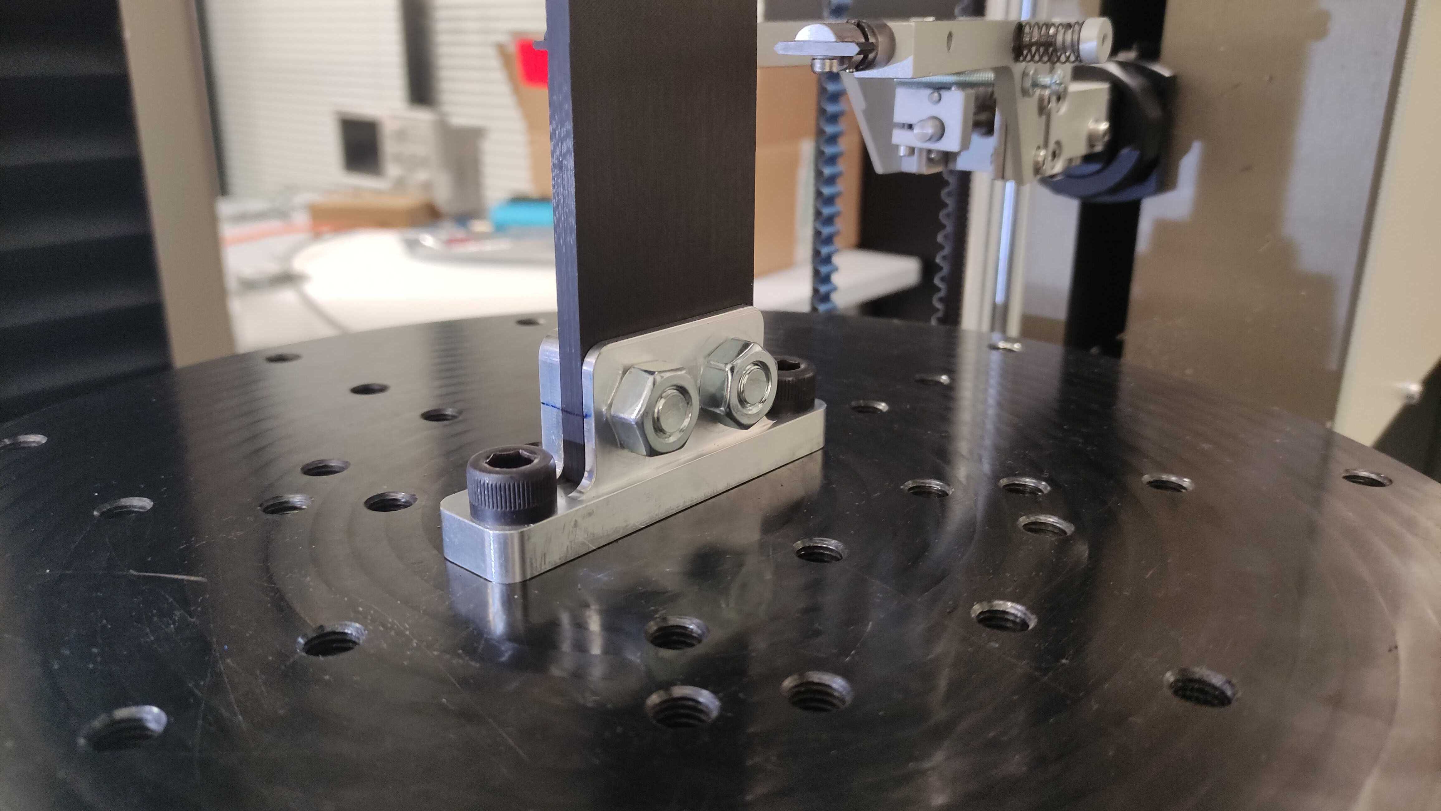
A first test run was first carried out on the original ear design with a screw torque of 45[Nm] as estimated. However, the data extracted from the machine was not well setup and did not allow to see the slip directly with the data. To see the slip, a pen line was made on the edge of the ear and the rod and the slip could be visually seen by the operators.
For this first test, the data measured by the machine is the force [N] vs the extension [%].
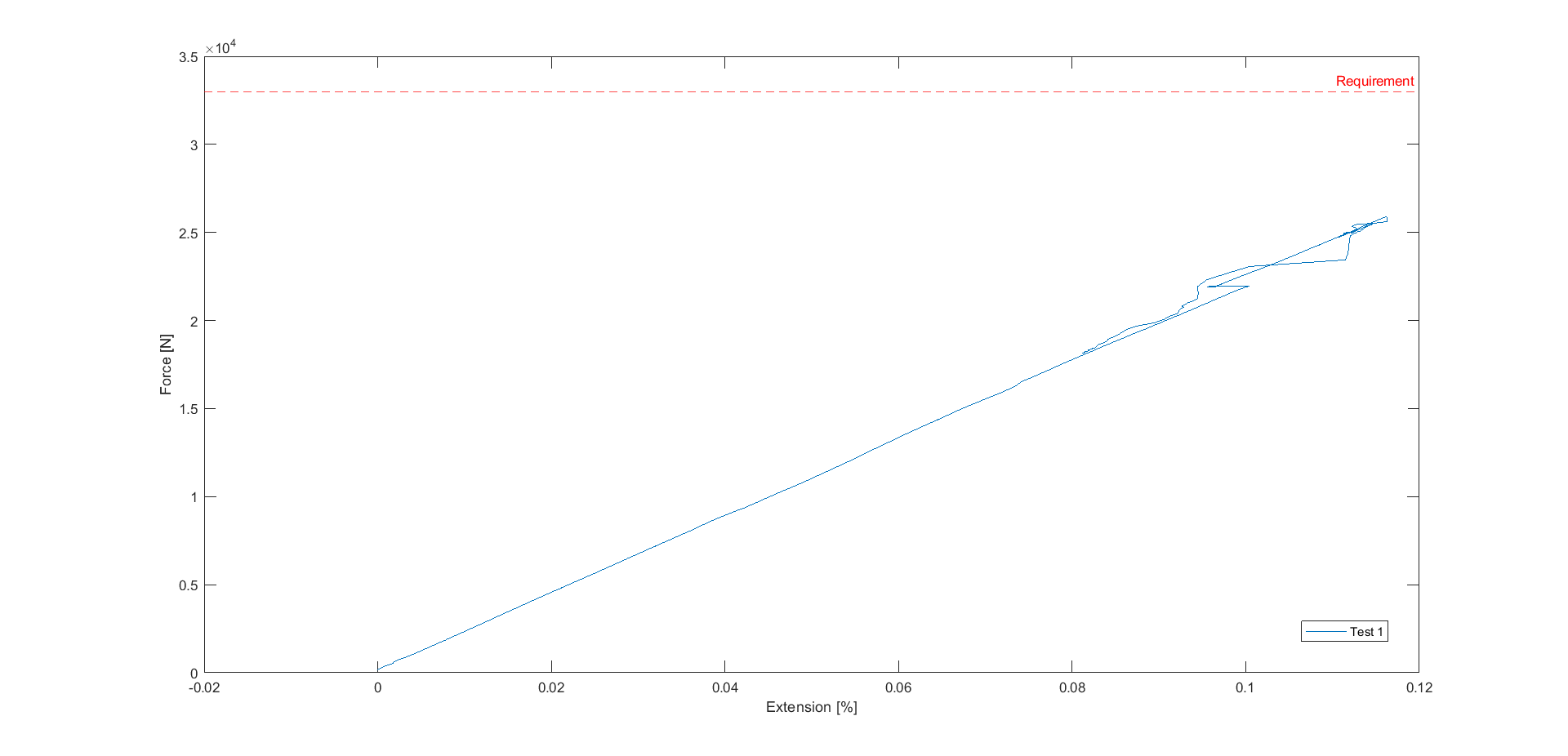
Slippage occured at around 10[kN] and the test was stopped before 33[kN] so as not to break the rod.
The rod slippage in the ear occurred at 10[kN], which is three times lower than the requirement of 33[kN]. Different parameters can be the reason for this result:
-
Since the rod's thickness varies, there may be a gap between the rod and the aluminum of the ear. Therefore, when tightening the screws, some of the torque put into the screws goes to deform the ear rather than being transformed into compressive force on the rod. In addition, the contact surface between the rod and the ear is reduced.
-
The friction coefficient between the CFRP and the aluminium is very difficult to estimate and depends on many different parameters. The calculations to define the tightening torque are therefore not very precise.
-
The friction coefficient between the nut and the screw and also between the nut and the ear are approximations and were not experimentally defined. This further increases errors when calculating the tightening torque of screws.
In order to improve these points, new ear designs were produced and a test on the screws was carried out to determine the maximum torque that can be applied during tightening.
¶ Torque screw test
As explained in the DDF, it was not possible to change the screw size and length because of the limited available space between the internal diameter and the integration diameter. The only possiblity to increase the normal force for friction is to increase the torque.
A test was carried out on a sample of 17 screws, where they were screwed in at 5Nm increments until the screw broke. The main results are given below. All the values corresponds to the torque at which the screw broke.
| Minimum [Nm] | Maximum [Nm] | Mean [Nm] | Standard Deviation |
|---|---|---|---|
| 70 | 120 | 94.88 | 15.54 |
All the values corresponds to the torque at which the screw broke.
The mean value for the maximum torque before rupture is around 95, with a standard deviation of 15. This means that most screws break above 80[Nm]. Moreover, on the 17 screws tested, only one broke at 70[Nm].
Consequently, it has been decided that the screws can be easily tightened up to 70[Nm].
¶ Second test session
During this second test session, multiple ear designs and configurations were tested, with all the screws tightened with a 70[Nm] torque.
The different ears tested are detailed in the document 2024_C_ST_INTERNAL-STRUCTURE-SCREWS_TSP.
Carbon gripper was used for the test with the "Classic ear", which increases the friction coefficient between the CFRP rod and the aluminum surfaces of the ear.
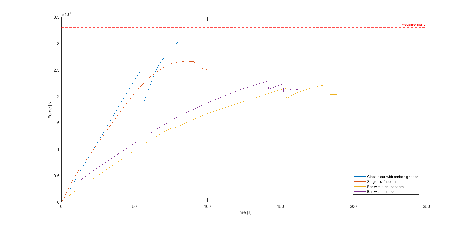
The results obtained here with the machine are the force [N] vs time [s]. Since the displacement of the transverse of the machine is constant at a speed of 2[mm/min], any slippage of the rod in the ear results in a change in the slope of the curve.
This test is the only one that was done with the remaining rod from the previous tests and still had the GRP tabs. The properties of the rod can therefore be affected and there can be slippage at the grips of the machine because of the tabs.
With this configuration, a load of 33[kN] could be reached, with only a small slippage of the rod in the ear which is not very significant.
Looking at the graph, a huge drop happened at around 25[kN]. This occured because the tabs slipped, causing this drop on the graph, but has nothing to do with the performance of the ear.
The Single Surface Ear configuration reached up to 25[kN] before the rod slipped sharply in the ear.
This design did not achieve the desired results because the ear is attached to the base only on one side, the other part of the ear is just attached to the rod. As a consequence, the screws slipped into their housing and moved with the rod.
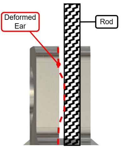
Because of the geometry of the ear and the fixation plate of the testing machine, the screws to fix the ear on the machine are placed further from the ear. During the test the base of the ear was deformed which resulted in a curve with a lower slope.
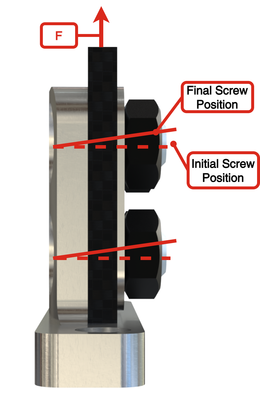
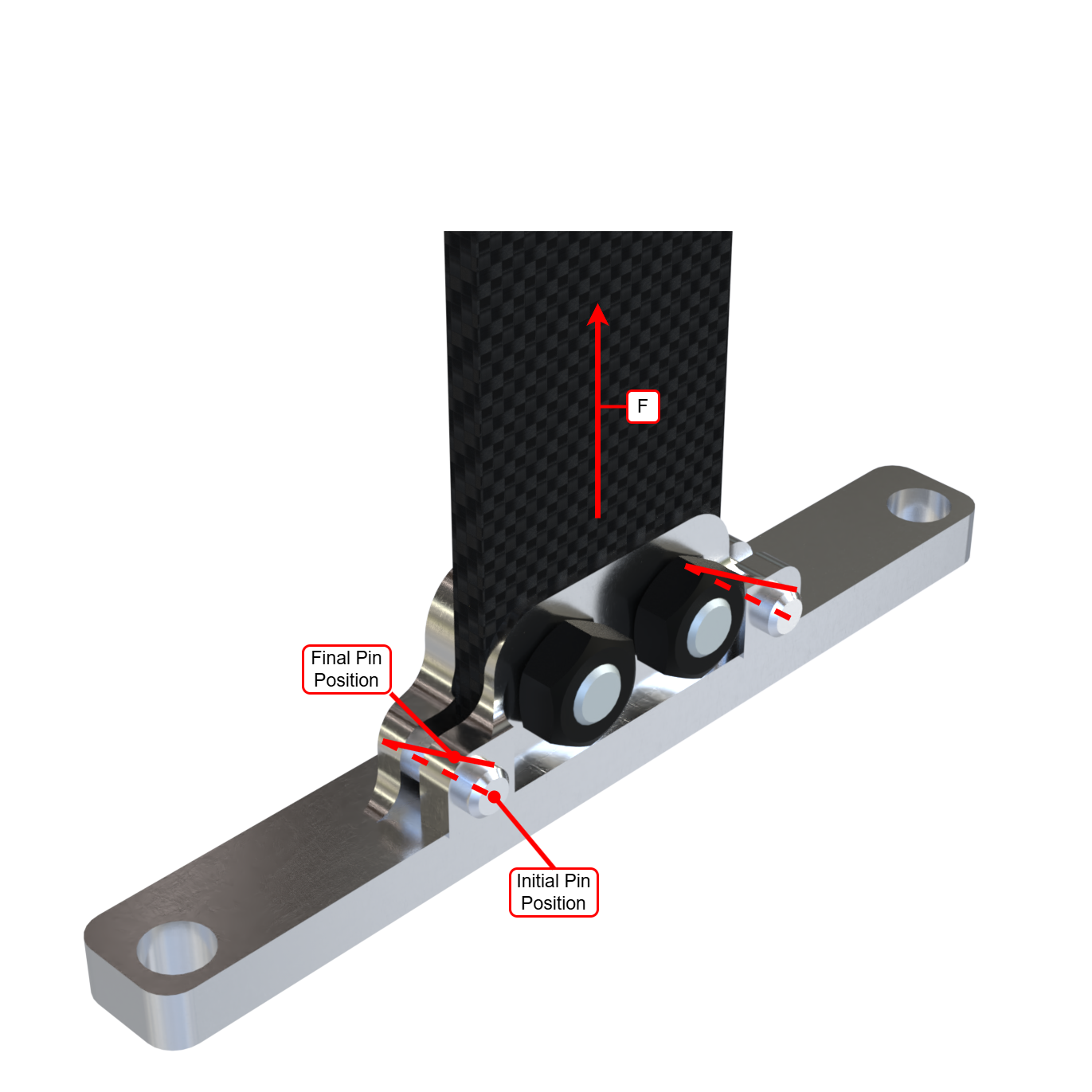
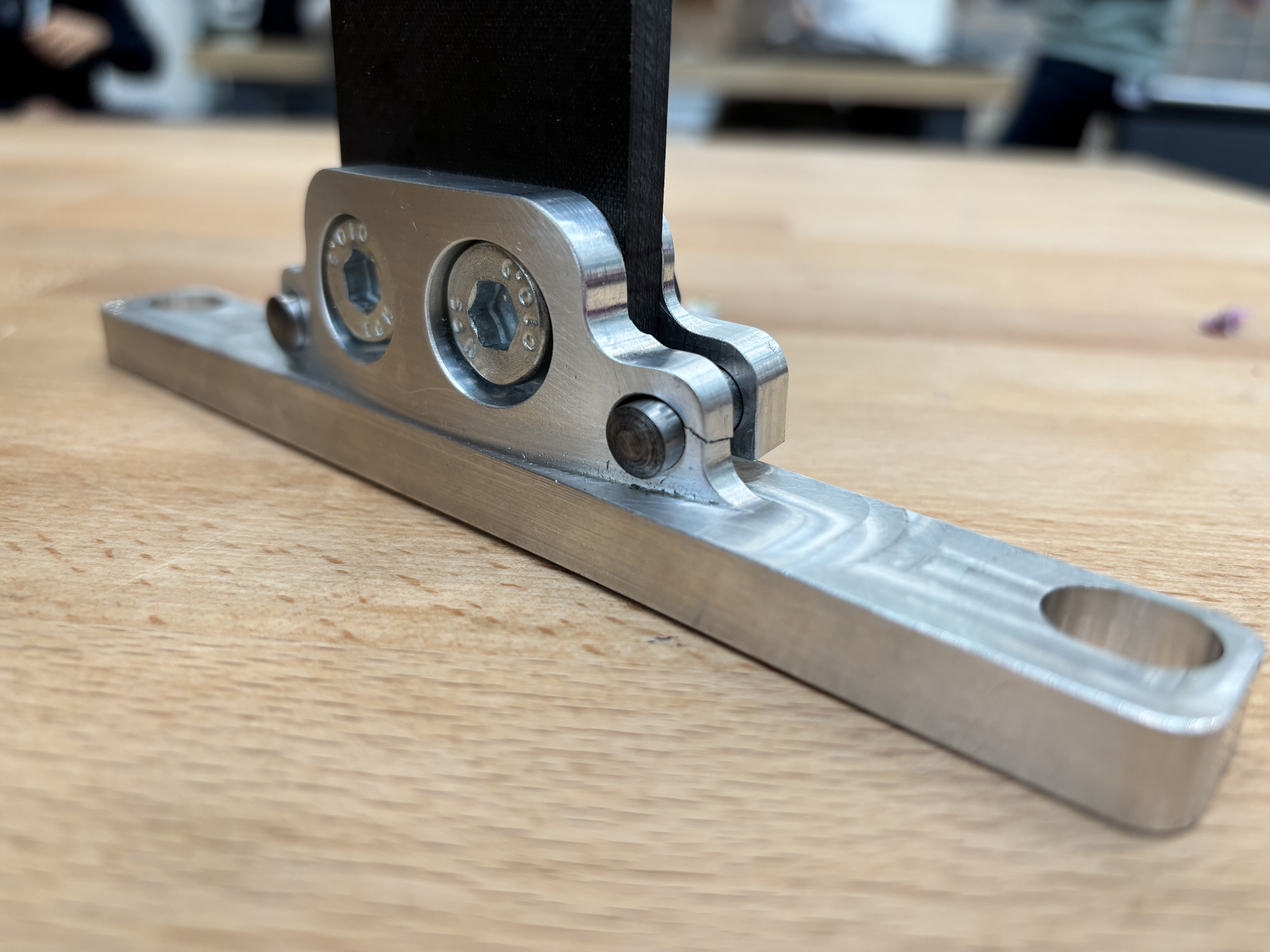
The Ear with pins, no teeth configuration reached up to 21.4[kN] before the pin housing in the ear broke.
The two drops on the graph correspond to the two times when the pin housings broke, one after the other.
The rupture of the housing of the pins is due to play between the pin and the ear in the housing. So, once loaded the part of the pin in the removable ear part moves upwards, following the movement of the rod. The angle being at a certain angle towards the vertical, the stresses were concentrated in the edge of the pin housing causing the rupture.
Because of the geometry of the ear and the fixation plate of the testing machine, the screws to fix the ear on the machine are placed further from the ear. During the test the base of the ear was deformed which resulted in a curve with a lower slope.
The Ear with pins, teeth configuration reached up to 22.8[kN] before the pin housing in the ear broke.
This configuration has a similar rupture mode than the previous one. The housing of the pins broke because of the play between the pins and the ear and the rotation of the pins. However, the maximum load is higher because the teeth further prevents rod slippage by increasing the coefficient of friction between the ear and the rod.
The "Classic Ear" configuration with a torque of 70[Nm] for the screws withstands the load of 33[kN] in traction given by the requirement.
Two other tests were performed with the "Classic Ear", 70 [Nm] torque for the screws and no carbon gripper to check if the design still works without carbon gripper. Both times a load of 33[kN] could be applied without breaking the ear or the rod.
¶ Pass Fail/Criteria
Since the 33[kN] load requirement was only reached for the "Classic Ear" configuration, the criterion are only considered for this configuration.
| Criteria | Pass/Fail ? |
|---|---|
| No displacement of the rod inside the ear with a load of 33[kN] | Fail |
| No ear deformation | Pass |
| No cracks | Pass |
| The sample didn't slip inside the grips | Fail |
With this configuration the rod slips a little in the ear, but the slip is very light which makes the configuration still usable for launch.
¶ Requirements which were verified
- 2024_C_SE_ST_INTERNAL-STRUCTURE_REQ_01
Declaration of purpose
The internal structure shall withstand all main loads experienced by the LV. - 2024_C_SE_ST_INTERNAL-STRUCTURE_REQ_04
Axial traction
The internal structure shall withstand [132000]N of axial tensile loads.
¶ Requirements which were not verified
With the "Classic Ear" and a torque of 70[Nm], all the requirements which had to be verified with these tests were respected.
¶ Conclusion
These tests have greatly increased our understanding of the rod attachment system with the "ears" and have highlighted many complexities and errors that were not considered during the design process.
The classic ear design with a torque of 70 [Nm] supports the requirements loads and can be used for Firehorn.
However, the tests have helped to identify the main negative points of this design, which can be improved later for next-generation rockets. In addition, testing other ear designs lays the foundation for future research and helps guide future students on the most optimal choice of ears for future rockets.